Table of Contents
Advertisement
InteliMains
Mains Circuit Breaker and Master Generator
Circuit Breaker Applications
IM-NT-BB, IM-NTC-BB, IM-NT
SW version 3.2.0, September 2015
NT
®
Copyright ©2015 ComAp a.s.
Kundratka 17, 180 00 Praha 8, Czech Republic
Tel: +420 246 012 111, Fax: +420 266 316 647
E-mail:info@comap.cz, www.comap.cz
Reference Guide
ComAp a.s.
Advertisement
Table of Contents

Summary of Contents for ComAp InteliMains NT IM-NT-BB
- Page 1 Mains Circuit Breaker and Master Generator Circuit Breaker Applications IM-NT-BB, IM-NTC-BB, IM-NT SW version 3.2.0, September 2015 Reference Guide Copyright ©2015 ComAp a.s. ComAp a.s. Kundratka 17, 180 00 Praha 8, Czech Republic Tel: +420 246 012 111, Fax: +420 266 316 647 E-mail:info@comap.cz, www.comap.cz...
-
Page 2: Table Of Contents
Selection of the language in InteliMains-NT(C)-BaseBox ..........38 Password management ......................39 4.5.1 User administration ......................39 4.5.2 Access group setting in GenConfig ................. 40 4.5.3 Password break protection ....................40 InteliMains , SW version 3.2.0 InteliMains-NT-MCB-MGCB-3.2.0-Reference Guide.pdf, ©ComAp – April 2015... - Page 3 Time and Date Intercontroller Sharing ................121 7.16.4 Summer Time Mode ...................... 121 7.17 User Buttons ........................... 121 7.18 Remote Control Function......................122 7.19 Virtual Peripheral Inputs-Outputs (VPIO) module ..............123 InteliMains , SW version 3.2.0 InteliMains-NT-MCB-MGCB-3.2.0-Reference Guide.pdf, ©ComAp – April 2015...
- Page 4 11.2.14 Group: Timer settings ....................281 11.2.15 Group: Act. calls/SMS ....................286 11.2.16 Group: Date/Time ......................292 Values ............................ 295 12.1 Table of values ........................295 12.1.1 Group: Mains values ...................... 295 InteliMains , SW version 3.2.0 InteliMains-NT-MCB-MGCB-3.2.0-Reference Guide.pdf, ©ComAp – April 2015...
- Page 5 14.2 Table of binary output functions ..................... 393 Analog Input functions ......................430 15.1 Virtual and physical modules ....................430 15.2 Table of analog input functions ....................431 User Notes ..........................435 InteliMains , SW version 3.2.0 InteliMains-NT-MCB-MGCB-3.2.0-Reference Guide.pdf, ©ComAp – April 2015...
-
Page 6: Document Information
Pressing F1 in the GenConfig and InteliMonitor setpoint, values or configuration window will open the help with the context of currently selected setpoint, value and binary input or output function. InteliMains , SW version 3.2.0 InteliMains-NT-MCB-MGCB-3.2.0-Reference Guide.pdf, ©ComAp – April 2015... -
Page 7: Available Related Documentation
Application Guide for InteliGen NT, InteliSys NT and IG/IS-NT-Application Guide 05-2013.pdf InteliMains NT systems Troubleshooting guide for InteliGen NT, InteliSys NT, IG/IS-NT Troubleshooting Guide 08-2014.pdf InteliMains NT and related accessories InteliMains , SW version 3.2.0 InteliMains-NT-MCB-MGCB-3.2.0-Reference Guide.pdf, ©ComAp – April 2015... -
Page 8: Clarification Of Notation
EC Low Voltage Directive No: 73/23 / EEC and EC Electromagnetic Compatibility Directive 89/336 / EEC based on its design and type, as brought into circulation by us. InteliMains , SW version 3.2.0 InteliMains-NT-MCB-MGCB-3.2.0-Reference Guide.pdf, ©ComAp – April 2015... -
Page 9: System Overview
InteliVision-8 and InteliVision-5. For more information on these products, please go to comap.cz web pages. The controller automatically connects the group of gen-sets to the Mains. It features mains failure detection using integrated Mains protections, MCB and MGCB synchronization, configuration level switches based on Mains import or object consumption. -
Page 10: Configurability And Monitoring
One of the key features of the controller is the system’s high level of adaptability to the needs of each individual application and wide possibilities for monitoring. This can be achieved by configuring and using the powerful ComAp PC/mobile tools. Supported configuration and monitoring tools: ... -
Page 11: Winscope
View of actual/historic trends in controller On-line change of controllers’ parameters for easy regulator setup 2.2.4 WebSupervisor Web-based system for monitoring and controlling ComAp controllers. See more at the WebSupervisor webpage. This tool provides the following functions: Site and fleet monitoring ... -
Page 12: Installation
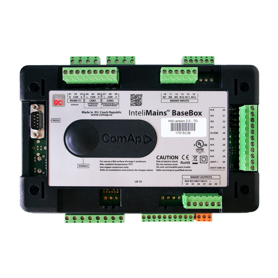
RS232 Communication port CAN1 Communication port (for extension modules) CAN2 Communication port (for intercontroller communication and monitoring) USB Communication port RJ45 (Ethernet) Communication port InteliMains , SW version 3.2.0 InteliMains-NT-MCB-MGCB-3.2.0-Reference Guide.pdf, ©ComAp – April 2015... -
Page 13: Im-Nt Installation Instructions
Locate four sockets for screw holders Insert the unit into cut-out in a switchboard and Tighten as required to fix the controller in the insert all four screw holders accordingly to their position positions InteliMains , SW version 3.2.0 InteliMains-NT-MCB-MGCB-3.2.0-Reference Guide.pdf, ©ComAp – April 2015... -
Page 14: Terminal Diagram, Dimensions
RS485 CAN1 CAN2 Extension Intercontroller RS232 Grounding Mains Aux Current measurement +PWR BOUT Binary outputs 170 (6,7") Cutout for IG-XX/IM-NT 113 x 175 mm 4,4 x 6,9” 185 (7,3") InteliMains , SW version 3.2.0 InteliMains-NT-MCB-MGCB-3.2.0-Reference Guide.pdf, ©ComAp – April 2015... -
Page 15: Package Contents
This portion of Instalation instructions is dedicated to the InteliMains-NT-BaseBox and InteliMains-NTC-BaseBox controllers without built-in display. If you have version with built-in display of the controller, please refer to the section 3.1. InteliMains , SW version 3.2.0 InteliMains-NT-MCB-MGCB-3.2.0-Reference Guide.pdf, ©ComAp – April 2015... -
Page 16: Mounting
Guide) standard rail (rail openings on InteliVision 5 are fixed so there is only one possible way how to mount the controller to it) InteliMains , SW version 3.2.0 InteliMains-NT-MCB-MGCB-3.2.0-Reference Guide.pdf, ©ComAp – April 2015... - Page 17 Locate four screw holes on the front of the Insert provided screws and use them to secure controller the controller mounted to InteliVision 5 (screws fit into InteliVision 5 holder pieces) InteliMains , SW version 3.2.0 InteliMains-NT-MCB-MGCB-3.2.0-Reference Guide.pdf, ©ComAp – April 2015...
-
Page 18: Terminal Diagram, Dimensions
AOUT - RS485 Analog output Universal Ethernet Binary outputs (NTC only) AOUT COM (NTC only) 9-12 Power Mains Aux Binary outputs Current measurement IM-NTC-BB only IM-NTC-BB only 56.5 68.5 InteliMains , SW version 3.2.0 InteliMains-NT-MCB-MGCB-3.2.0-Reference Guide.pdf, ©ComAp – April 2015... -
Page 19: Package Contents
Tightening torque, allowable wire size and type, for the Field-Wiring Terminals: For Mains(Bus) Voltage, Generator Voltage a Current terminals Specified tightening torque is 0,56Nm (5,0 In-lb) Use only diameter 2,0-0,5mm (12-26AWG) conductor, rated for 90°C minimum. InteliMains , SW version 3.2.0 InteliMains-NT-MCB-MGCB-3.2.0-Reference Guide.pdf, ©ComAp – April 2015... -
Page 20: Grounding (General)
Binary outputs connection controller, extension modules or relays to T1A or T2A a power source. Extension module See the diagram for proper fusing. IM-NT-BB IM-NTC-BB IM-NT Battery 24V DC InteliMains , SW version 3.2.0 InteliMains-NT-MCB-MGCB-3.2.0-Reference Guide.pdf, ©ComAp – April 2015... -
Page 21: Voltage And Current Inputs (General)
(WrongPhSequence detected by the controller) but this is not detected if the phases are just rotated (i.e. instead of phase sequence L1, L2, L3, phase sequence is e.g. L2, L3, L1. InteliMains , SW version 3.2.0 InteliMains-NT-MCB-MGCB-3.2.0-Reference Guide.pdf, ©ComAp – April 2015... -
Page 22: Binary Input Wiring (General)
+PWR BOUT is used. If Binary outputs are connected directly to the power source, additional fuse should be used. +PWR BOUT Controller Controller Battery 24V Battery 24V If +PWR BOUT is used, it increases power consumption of the controller. InteliMains , SW version 3.2.0 InteliMains-NT-MCB-MGCB-3.2.0-Reference Guide.pdf, ©ComAp – April 2015... -
Page 23: Im-Nt-Bb And Im-Ntc-Bb
Low side or High side function of binary outputs can be chosen in configuration tool GenConfig in Modules tab. This configuration is used for all binary inputs available on the controller. InteliMains , SW version 3.2.0 InteliMains-NT-MCB-MGCB-3.2.0-Reference Guide.pdf, ©ComAp – April 2015... -
Page 24: Analog Input And Output Wiring
3 and Analog output wiring. Note, that battery should be also grounded to common ground in all cases! AI COM AI COM AOUT + Internal AOUT AOUT + Internal AOUT Battery 24V Battery 24V InteliMains , SW version 3.2.0 InteliMains-NT-MCB-MGCB-3.2.0-Reference Guide.pdf, ©ComAp – April 2015... - Page 25 Below 750Ω = Inactive Between 750Ω and 2400Ω = Active Below 10 Ω or Over 2400Ω = sensor failure (wire shorted or interrupted) 100R AI COM AOUT + Internal AOUT Battery 24V InteliMains , SW version 3.2.0 InteliMains-NT-MCB-MGCB-3.2.0-Reference Guide.pdf, ©ComAp – April 2015...
-
Page 26: Can And Rs485 Bus Wiring
≥ 75% (delay ≤ 4.4 ns/m) Propagation velocity ≥ 0.25 mm Wire crosscut ≤ 2dB/100 m Attenuation (@1MHz) RS485 BUS TOPOLOGY See the website www.can-cia.org for information about the CAN bus, specifications, etc. InteliMains , SW version 3.2.0 InteliMains-NT-MCB-MGCB-3.2.0-Reference Guide.pdf, ©ComAp – April 2015... -
Page 27: Wiring Examples
3. In case of surge hazard: 3106A Paired – EIA Industrial RS-485 PLTC/CM (1x2+1 conductors) 1 – ICTURE SHORTER DISTANCES ALL NETWORK COMPONENTS WITHIN ONE ROOM 2 – ICTURE LONGER DISTANCES CONNECTION BETWEEN ROOMS WITHIN ONE BUILDING InteliMains , SW version 3.2.0 InteliMains-NT-MCB-MGCB-3.2.0-Reference Guide.pdf, ©ComAp – April 2015... -
Page 28: Extension Modules (General)
CONNECTION OUT OF BUILDING IN CASE OF STORM ETC 3.12 Extension modules (general) For detailed description of several available extension modules for InteliMains please refer to the IGS-NT-Instalation Guide. InteliMains , SW version 3.2.0 InteliMains-NT-MCB-MGCB-3.2.0-Reference Guide.pdf, ©ComAp – April 2015... -
Page 29: Putting It Into Operation
A direct connection can be realized by RS232 connection or USB connection (available on NTC BaseBox only). Figures below illustrate the connection setting in GenConfig and InteliMonitor. GenConfig InteliMonitor Select according COM port, adjust CAN address and enter password (optional for locked configuration). InteliMains , SW version 3.2.0 InteliMains-NT-MCB-MGCB-3.2.0-Reference Guide.pdf, ©ComAp – April 2015... -
Page 30: Modem Connection
Access Code for remote connection. Enter password (optional for locked configuration). It is possible to adjust number of rings before the controller accepts the connection from modem – use Comms settings:NumberRings AA. InteliMains , SW version 3.2.0 InteliMains-NT-MCB-MGCB-3.2.0-Reference Guide.pdf, ©ComAp – April 2015... -
Page 31: Internet Connection
Enter Access Code for remote connection. Enter password (optional for locked configuration). The controller must have public IP address or it must be reachable for connection in the specific network. InteliMains , SW version 3.2.0 InteliMains-NT-MCB-MGCB-3.2.0-Reference Guide.pdf, ©ComAp – April 2015... -
Page 32: Airgate Connection
GenConfig InteliMonitor Enter AirGate address of a server with AirGate service (currently airgate.comap.cz). Select CAN address of the controller you want to connect to. Enter AirGate ID of the controller (InternetBridge) you want to connect to (AirGate ID is assigned automatically if the controller is properly connected to the Internet and corresponding AirGate setting is enabled. -
Page 33: Connection To Multiple Controllers
Internet multiple connection (use Internet Bridges IPs for connection to NTC BaseBox controllers as well Airgate multiple connection (fill in AirGate IDs for each controller, when using InternetBridge fill in InternetBridge AirGate ID for each controller) InteliMains , SW version 3.2.0 InteliMains-NT-MCB-MGCB-3.2.0-Reference Guide.pdf, ©ComAp – April 2015... -
Page 34: Modification Of Configuration, Setpoints Etc
Do not forget that all changes in InteliMonitor are sent to the connected controller and controller immediately acts on it. Do not change CAN address of the controller or connection is lost and need to be re-established with new CAN address. InteliMains , SW version 3.2.0 InteliMains-NT-MCB-MGCB-3.2.0-Reference Guide.pdf, ©ComAp – April 2015... -
Page 35: Programming Of A Controller
Open GenConfig and select “FW upgrade (default configuration)” From the following table select FW that is required or click open and browse your files to find firmware in non-default location InteliMains , SW version 3.2.0 InteliMains-NT-MCB-MGCB-3.2.0-Reference Guide.pdf, ©ComAp – April 2015... - Page 36 3.1.4 (IM-NT-GC) or 3.2.4 (IM-NT-BB and IM-NTC-BB) Programming starts momentarily When the programming is done following dialog appears Follow the instructions and press OK. Following diagram will appear and programming is done InteliMains , SW version 3.2.0 InteliMains-NT-MCB-MGCB-3.2.0-Reference Guide.pdf, ©ComAp – April 2015...
- Page 37 Additional dialog warns you that the setpoints may have improper values. Change the configuration in normal way. InteliMains , SW version 3.2.0 InteliMains-NT-MCB-MGCB-3.2.0-Reference Guide.pdf, ©ComAp – April 2015...
-
Page 38: Changing The Language
Touch. If you need to use for some reason IG or IS-Display please refer to the chapter 4.4.1 for the instructions regarding built-in display which works the same as the external displays. InteliMains , SW version 3.2.0 InteliMains-NT-MCB-MGCB-3.2.0-Reference Guide.pdf, ©ComAp – April 2015... -
Page 39: Password Management
Log in as a different user to change password for that particular user. Newly enabled user has always default password “0”. InteliMains , SW version 3.2.0 InteliMains-NT-MCB-MGCB-3.2.0-Reference Guide.pdf, ©ComAp – April 2015... -
Page 40: Access Group Setting In Genconfig
Controller is blocked for 5 minutes if there were 6 attempts to insert incorrect password. In case of another six failed attempts (after the period of blocking elapses) the blocking period is 30, 60, 120 and 240 minutes long respectively. InteliMains , SW version 3.2.0 InteliMains-NT-MCB-MGCB-3.2.0-Reference Guide.pdf, ©ComAp – April 2015... - Page 41 30 minutes after the controller reset there will be again 30 minutes remaining). After the correct password is inserted the PBP blocking period for next 6 failed attempts is reverted back to 5 minutes. InteliMains , SW version 3.2.0 InteliMains-NT-MCB-MGCB-3.2.0-Reference Guide.pdf, ©ComAp – April 2015...
-
Page 42: Related Tools
PLC Editor – it can be used to create and modify built-in PLC functions For more information on Screen Editor use help in GenConfig (Help -> Screen Editor Help). For more information on PLC Editor use GenConfig Reference Guide. InteliMains , SW version 3.2.0 InteliMains-NT-MCB-MGCB-3.2.0-Reference Guide.pdf, ©ComAp – April 2015... -
Page 43: Operator Guide
InteliVision 5 or 8 please refer to the section 5.1. For extensive information regarding operator control use operator guide for IGS-NT since general functions of InteliVision displays are the same for InteliGen, InteliSys and InteliMains. InteliMains , SW version 3.2.0 InteliMains-NT-MCB-MGCB-3.2.0-Reference Guide.pdf, ©ComAp – April 2015... -
Page 44: Firmware And Archives
The firmware for GC controllers do not support functions described above, although it can still be used in combination with BaseBox type controllers. It is possible to use specialized InteliMains-NT firmware for InteliSys controllers. This firmware supports all the functions mentioned above. InteliMains , SW version 3.2.0 InteliMains-NT-MCB-MGCB-3.2.0-Reference Guide.pdf, ©ComAp – April 2015... -
Page 45: Function Description
AcallCH4-Addr Time zone AcallCH5-Addr Alternative brightness for It is possible to choose two different built-in levels of brightness and switch them with Alt brightness InteliGen logical binary input. display. InteliMains , SW version 3.2.0 InteliMains-NT-MCB-MGCB-3.2.0-Reference Guide.pdf, ©ComAp – April 2015... - Page 46 Nominal freq BusNomVph-ph function are directly dependant of these Nom frq offset Nomin current settings. For additional information on NominMainsImp protections please refer to separate chapter Protections and Alarm Management. InteliMains , SW version 3.2.0 InteliMains-NT-MCB-MGCB-3.2.0-Reference Guide.pdf, ©ComAp – April 2015...
- Page 47 Controller detects any problems in communication communication with extension modules error of (it is possible to adjust corresponding PeriphCommErr peripheral level of protection in GenConfig) and modules issues alarm based on it. InteliMains , SW version 3.2.0 InteliMains-NT-MCB-MGCB-3.2.0-Reference Guide.pdf, ©ComAp – April 2015...
- Page 48 Force value 13 to use value forcing please refer to a ORCE ALUE separate chapter. Force value 14 ORCE ALUE Force value 15 ORCE ALUE Force value 16 ORCE ALUE InteliMains , SW version 3.2.0 InteliMains-NT-MCB-MGCB-3.2.0-Reference Guide.pdf, ©ComAp – April 2015...
- Page 49 Ld shed f lvl1 chapter. Ld reconDelay3 Ld shed f lvl2 AutoLd recon Ld shed f lvl3 HED STAGE Ld shedDelay1 HED STAGE Ld shedDelay2 HED STAGE Ld shedDelay3 ANUAL ECON InteliMains , SW version 3.2.0 InteliMains-NT-MCB-MGCB-3.2.0-Reference Guide.pdf, ©ComAp – April 2015...
- Page 50 It is possible to use permanent logical Permanent binary function that is always logical 0 or OGICAL logical 0 or 1 logical 1. It may used for various OGICAL outputs purposes. InteliMains , SW version 3.2.0 InteliMains-NT-MCB-MGCB-3.2.0-Reference Guide.pdf, ©ComAp – April 2015...
- Page 51 This function is used to limit process (e.g. control Island enable parallel operation is not allowed). This ParallelEnable function is complex and it is described in Synchro enable a separate chapter. InteliMains , SW version 3.2.0 InteliMains-NT-MCB-MGCB-3.2.0-Reference Guide.pdf, ©ComAp – April 2015...
- Page 52 There is whole variaty of regulation Load gain functions in the controller. Please refer to Load int a separate chapter to find out more. Voltage gain Voltage Int PF gain PF int InteliMains , SW version 3.2.0 InteliMains-NT-MCB-MGCB-3.2.0-Reference Guide.pdf, ©ComAp – April 2015...
- Page 53 MGCBparalClose the Mains Moreover, you can use this function to voltage distribute Mains voltage along bus even if no gen-set is running. InteliMains , SW version 3.2.0 InteliMains-NT-MCB-MGCB-3.2.0-Reference Guide.pdf, ©ComAp – April 2015...
- Page 54 GPS Latitude connected to the CAN. Time is positioning with Longitude broadcasted to all the controllers on CAN InternetBridge- bus. Position is available for monitoring and for WebSupervisor. InteliMains , SW version 3.2.0 InteliMains-NT-MCB-MGCB-3.2.0-Reference Guide.pdf, ©ComAp – April 2015...
- Page 55 SER MASK possible to use these inputs to show SER MASK particular screens in InteliVision 5. For SER MASK more information on this function please refer to the separate chapter. InteliMains , SW version 3.2.0 InteliMains-NT-MCB-MGCB-3.2.0-Reference Guide.pdf, ©ComAp – April 2015...
- Page 56 Controller automatically detects if phases measurement is connected in wrong Wrong Phases sequence (note that the wrong sequence RONG sequence is not detected if the phases are just rotated, i.e. L2-L3-L1) InteliMains , SW version 3.2.0 InteliMains-NT-MCB-MGCB-3.2.0-Reference Guide.pdf, ©ComAp – April 2015...
-
Page 57: Modes
YS START STOP connect to the bus. System goes to parallel to Mains operation and remains there. The group required power is given by currently selected mode of Load control. InteliMains , SW version 3.2.0 InteliMains-NT-MCB-MGCB-3.2.0-Reference Guide.pdf, ©ComAp – April 2015... - Page 58 MGCB closes enable and Synchro Synchro enable = enable NONE or REVERSE FwResBreak Parallel enable = Test on Load DISABLED MCB opens with Break Synchro enable = ANY SETTING InteliMains , SW version 3.2.0 InteliMains-NT-MCB-MGCB-3.2.0-Reference Guide.pdf, ©ComAp – April 2015...
- Page 59 Synchro deactivation Synchro enable = enable DISABLED NONE or FORWARD FwRetBreak Parallel enable = DISABLED ReturnTo Return with Break MGCB opens ENABLED Synchro enable = Mains ANY SETTING InteliMains , SW version 3.2.0 InteliMains-NT-MCB-MGCB-3.2.0-Reference Guide.pdf, ©ComAp – April 2015...
- Page 60 ProcessControl:Synchro enable = NONE. Load is on gen-sets and the system is in Island operation. Mode is changed to AUT. Controller counts down AMF settings:Mains ret del and if InteliMains , SW version 3.2.0 InteliMains-NT-MCB-MGCB-3.2.0-Reference Guide.pdf, ©ComAp – April 2015...
-
Page 61: Process Limitation
NONE - Gen-sets will be started when the Mains fails. - Gen-sets will synchronize directly to the Mains (MGCB already closed) , i.e. synchronization transfer from Island to Parallel InteliMains , SW version 3.2.0 InteliMains-NT-MCB-MGCB-3.2.0-Reference Guide.pdf, ©ComAp – April 2015... - Page 62 - Island and Parallel operations are possible. - Transfer with synchronization from Island to REVERSE Parallel is enabled (Mains to Parallel N/A) - Gen-sets will not be started when the Mains fails. InteliMains , SW version 3.2.0 InteliMains-NT-MCB-MGCB-3.2.0-Reference Guide.pdf, ©ComAp – April 2015...
- Page 63 - Gen-sets will not be started when the Mains NONE fails. - Gen-sets will synchronize directly to the Mains (MGCB already closed), i.e. synchronization transfer from Mains to Parallel InteliMains , SW version 3.2.0 InteliMains-NT-MCB-MGCB-3.2.0-Reference Guide.pdf, ©ComAp – April 2015...
-
Page 64: Mcb
Gen-sets will not be started when the Mains fails. Island operation is possible. Transfer with synchronization via NONE InteliMains is not possible Gen-sets will be started when the Mains fails. InteliMains , SW version 3.2.0 InteliMains-NT-MCB-MGCB-3.2.0-Reference Guide.pdf, ©ComAp – April 2015... -
Page 65: System Start
Different load reserve sets may be used for starting of the system and for its usual run (e.g. selection of second load reserve set may be conditioned by MGCB ). It is particularly FEEDBACK InteliMains , SW version 3.2.0 InteliMains-NT-MCB-MGCB-3.2.0-Reference Guide.pdf, ©ComAp – April 2015... -
Page 66: Startupsynchronization
The automatic priority swapping function focuses on efficient run of gen-set in regards to running hours and gen-set size. 7.6.1 Power management limitations ARNING This section contains important information regarding power management function that are crucial for the correct function of power management. InteliMains , SW version 3.2.0 InteliMains-NT-MCB-MGCB-3.2.0-Reference Guide.pdf, ©ComAp – April 2015... -
Page 67: Basic Power Management
The gen-set performs load and VAR sharing whenever it is connected to the bus bar i.e. it is independent on whether the controller is in AUT or MAN mode or whether the power management is active or not. Do not confuse power management with load sharing. InteliMains , SW version 3.2.0 InteliMains-NT-MCB-MGCB-3.2.0-Reference Guide.pdf, ©ComAp – April 2015... - Page 68 Pwr management: NextStrt del. The shorter time always applies in such a case (counting in that part of NextStrt del may have already been elapsed). InteliMains , SW version 3.2.0 InteliMains-NT-MCB-MGCB-3.2.0-Reference Guide.pdf, ©ComAp – April 2015...
- Page 69 Sum of Nominal power of all gen-sets on the bus apart of the one, which is going to be stopped. ΣPg Sum of Actual power of all gen-sets on the bus = system load. BaseLd Baseload is given by the setpoint ProcessControl: #SysBaseLoad InteliMains , SW version 3.2.0 InteliMains-NT-MCB-MGCB-3.2.0-Reference Guide.pdf, ©ComAp – April 2015...
- Page 70 As shown above, the load of the system has increased above the level defined by the start condition – i.e. the load reserve is not sufficient as required by the setpoint Pwr management: #LoadResStrt. Further explication is provided in chapters Absolute Power Management and Relative Power Management InteliMains , SW version 3.2.0 InteliMains-NT-MCB-MGCB-3.2.0-Reference Guide.pdf, ©ComAp – April 2015...
- Page 71 Once loaded, the system load reserve is raised and becomes sufficient again. Please note the sum of nominal power of all gen-sets on the bus is increased by the nominal power of the additional gen-set. InteliMains , SW version 3.2.0 InteliMains-NT-MCB-MGCB-3.2.0-Reference Guide.pdf, ©ComAp – April 2015...
- Page 72 The cooling sequence follows before the gen-set is actually stopped. The gen-set is ready to be started if the system load increases again. InteliMains , SW version 3.2.0 InteliMains-NT-MCB-MGCB-3.2.0-Reference Guide.pdf, ©ComAp – April 2015...
- Page 73 Stopping sequence sequence Stopped and ready Gen 2 Running, loaded to PM Gen 1 Running, loaded BO Syst res OK Time Figure: Power management based on absolute load reserve InteliMains , SW version 3.2.0 InteliMains-NT-MCB-MGCB-3.2.0-Reference Guide.pdf, ©ComAp – April 2015...
- Page 74 Gen 3 Stopped and ready Running, loaded Gen 2 Stopped and ready Running, loaded Gen 1 Running, loaded BO Syst res OK Time Figure: Absolute Power management example InteliMains , SW version 3.2.0 InteliMains-NT-MCB-MGCB-3.2.0-Reference Guide.pdf, ©ComAp – April 2015...
- Page 75 LBI: LoadRes 2 LBI: LoadRes 2 LBI: LoadRes 2 Power Power Power management management management Controller 1 Controller 2 Controller 3 Figure: Example of using virtual shared peripheries for signal distribution InteliMains , SW version 3.2.0 InteliMains-NT-MCB-MGCB-3.2.0-Reference Guide.pdf, ©ComAp – April 2015...
- Page 76 Running, loaded ready Starting sequence Gen 2 Ready Running, loaded Stopped and ready Gen 1 Running, loaded BO Syst res OK Time Figure: Power management based on relative load reserve InteliMains , SW version 3.2.0 InteliMains-NT-MCB-MGCB-3.2.0-Reference Guide.pdf, ©ComAp – April 2015...
- Page 77 Stopped and Gen 3 Ready Running, loaded ready Stopped and Gen 2 Ready Running, loaded ready Gen 1 Running, loaded BO Syst res OK Time Figure: Relative Power management example InteliMains , SW version 3.2.0 InteliMains-NT-MCB-MGCB-3.2.0-Reference Guide.pdf, ©ComAp – April 2015...
- Page 78 LBI: LoadRes 2 LBI: LoadRes 2 LBI: LoadRes 2 Power Power Power management management management Controller 1 Controller 2 Controller 3 Figure: Example of using virtual shared peripheries for signal distribution InteliMains , SW version 3.2.0 InteliMains-NT-MCB-MGCB-3.2.0-Reference Guide.pdf, ©ComAp – April 2015...
- Page 79 Gen #4 Priority = 1 Gen #3 Priority = 2 Gen #2 Priority = 3 Gen #1 Priority = 4 Time Figure: Power management example - Priorities InteliMains , SW version 3.2.0 InteliMains-NT-MCB-MGCB-3.2.0-Reference Guide.pdf, ©ComAp – April 2015...
-
Page 80: Automatic Priority Swapping
Important setpoint: Pwr management: #PriorAutoSwap The Automatic priority swapping function does not change the setpoint Pwr management: Priority. The function sets the order of gen-sets by virtual values “engine priority”. InteliMains , SW version 3.2.0 InteliMains-NT-MCB-MGCB-3.2.0-Reference Guide.pdf, ©ComAp – April 2015... - Page 81 #RunHrsMaxDiff = 10h #RunHrsMaxDiff = 10h Control group = Control group = Control group = Control group = Control group = COMMON COMMON COMMON COMMON COMMON Figure: Running Hours Equalization example InteliMains , SW version 3.2.0 InteliMains-NT-MCB-MGCB-3.2.0-Reference Guide.pdf, ©ComAp – April 2015...
- Page 82 11 hours to equalize the RHE of both gen-sets and then additional #RunHrsMaxDiff + 1 hours (i.e. 11 + 10 + 1 = 22 hours). The evolution of RHE1 and RHE2 is shown on the figure below. InteliMains , SW version 3.2.0 InteliMains-NT-MCB-MGCB-3.2.0-Reference Guide.pdf, ©ComAp – April 2015...
- Page 83 SwapTimeG1 = 0 – 0 + 10 + 1 = 11 Similar way, we get the run time of gen-set 2 before next swapping: SwapTimeG2 = 11 – 11 + 10 + 1 = 11 InteliMains , SW version 3.2.0 InteliMains-NT-MCB-MGCB-3.2.0-Reference Guide.pdf, ©ComAp – April 2015...
- Page 84 Please refer to figure below to understand the evolution of RHE of gen-sets in this particular case. Step Figure: Running Hours Equalization example, 3 gen-sets with same initial RHE step RHE1 RHE2 RHE3 Run G1 (Δ RHE1) Run G2 (Δ RHE2) Run G3 (Δ RHE3) InteliMains , SW version 3.2.0 InteliMains-NT-MCB-MGCB-3.2.0-Reference Guide.pdf, ©ComAp – April 2015...
- Page 85 In the case Pwr management: #RunHrsMaxDiff is set to 0 and all gen-set in the group are at the same initial point (RHE are equal), the gen-set swapping happens every hour. InteliMains , SW version 3.2.0 InteliMains-NT-MCB-MGCB-3.2.0-Reference Guide.pdf, ©ComAp – April 2015...
- Page 86 Priority setpoints are not actually changed. Virtual values “engine priority” are used. If changing of priority setpoints is required, they need to be changed and RHE needs to disabled and enabled again for the changes to take place. InteliMains , SW version 3.2.0 InteliMains-NT-MCB-MGCB-3.2.0-Reference Guide.pdf, ©ComAp – April 2015...
- Page 87 This is normal and it prevents the system from overloading. Priority setpoints are not actually changed. Virtual values “engine priority” are used. InteliMains , SW version 3.2.0 InteliMains-NT-MCB-MGCB-3.2.0-Reference Guide.pdf, ©ComAp – April 2015...
- Page 88 This delay is depicted by the dashed orange line. Consequently, the handover up swap sequence is postponed by this delay. InteliMains , SW version 3.2.0 InteliMains-NT-MCB-MGCB-3.2.0-Reference Guide.pdf, ©ComAp – April 2015...
- Page 89 This delay is depicted by the dashed orange line. Consequently, the handover down swap sequence is postponed by this delay. InteliMains , SW version 3.2.0 InteliMains-NT-MCB-MGCB-3.2.0-Reference Guide.pdf, ©ComAp – April 2015...
- Page 90 The site contains 3 gen-sets, G1 is 200kW, G2 is 500kW and G3 is 1000kW. The reserve for start is adjusted to 50kW and for stop to 70kW. Following table describes available power bands: Gen-sets Nominal power [kW] Power band [kW] 0 .. 150 151 .. 450 InteliMains , SW version 3.2.0 InteliMains-NT-MCB-MGCB-3.2.0-Reference Guide.pdf, ©ComAp – April 2015...
- Page 91 Power band range [kW] #PwrBandContr1 0 .. 150 #PwrBandContr2 151 .. 450 #PwrBandContr3 1000 451 .. 950 #PwrBandContr4 G2+G3 1500 951 .. 1450 Fixed power band #5 G1+G2+G3 1700 >1450 InteliMains , SW version 3.2.0 InteliMains-NT-MCB-MGCB-3.2.0-Reference Guide.pdf, ©ComAp – April 2015...
- Page 92 READY READY LOADED READY READY READY LOADED Gen#2 READY LOADED READY LOADED LOADED LOADED READY LOADED READY 1 000 Gen#3 READY READY LOADED LOADED LOADED LOADED LOADED READY READY InteliMains , SW version 3.2.0 InteliMains-NT-MCB-MGCB-3.2.0-Reference Guide.pdf, ©ComAp – April 2015...
- Page 93 100 kW ENABLED ABS (kW) EFFICIENCY Gen-set #1 means that the CAN address of the controller is set to 1. The relevant setpoint is adjusted by Comms settings: Contr. address. InteliMains , SW version 3.2.0 InteliMains-NT-MCB-MGCB-3.2.0-Reference Guide.pdf, ©ComAp – April 2015...
- Page 94 LDS Swap [30h] stop Gen#5 joins start (LDS) start LDS Swap 1000 [40h] stop 1000 start Gen#5 joins InteliMains , SW version 3.2.0 InteliMains-NT-MCB-MGCB-3.2.0-Reference Guide.pdf, ©ComAp – April 2015...
- Page 95 (LDS) 1000 InteliMains , SW version 3.2.0 InteliMains-NT-MCB-MGCB-3.2.0-Reference Guide.pdf, ©ComAp – April 2015...
-
Page 96: Minimum Running Power
#MinRunPower 1 considered if LBI MinRun power 1 activated #MinRunPower 2 considered if LBI MinRun power 2 activated #MinRunPower 3 considered if LBI MinRun power 3 activated InteliMains , SW version 3.2.0 InteliMains-NT-MCB-MGCB-3.2.0-Reference Guide.pdf, ©ComAp – April 2015... - Page 97 LBI: MiniRun Power 2 LBI: MiniRun Power 2 Power Power Power management management management #Controller 1 #Controller 2 #Controller 3 Figure: Example of using virtual shared peripheries for signal distribution InteliMains , SW version 3.2.0 InteliMains-NT-MCB-MGCB-3.2.0-Reference Guide.pdf, ©ComAp – April 2015...
-
Page 98: Control Groups
Once the BTB breaker is closed, the control group 2 and 3 become new group 2+3. The closed BTB and the group link function influence the load reserve (i.e. increased by added gen-set of added gen- sets). Load sharing applies for all gen-sets. InteliMains , SW version 3.2.0 InteliMains-NT-MCB-MGCB-3.2.0-Reference Guide.pdf, ©ComAp – April 2015... -
Page 99: Load Shedding Based On Active Power
Immediately when MGCB is closed in MAN mode by button (transit to island from parallel operation). If no Load Shedding outputs are configured, there is no record to history and no screen timer indication of the activity of this function. InteliMains , SW version 3.2.0 InteliMains-NT-MCB-MGCB-3.2.0-Reference Guide.pdf, ©ComAp – April 2015... -
Page 100: Load Shedding Based On Frequency
If manual reconnection of the load is desired, the Load shedding:AutoLd recon setpoint needs to be disabled (DISABLED) and the M binary input needs to be configured. ANUAL ECON InteliMains , SW version 3.2.0 InteliMains-NT-MCB-MGCB-3.2.0-Reference Guide.pdf, ©ComAp – April 2015... - Page 101 BO LdShed stage 1 BO LdShed stage 2 BO LdShed stage 3 BI ManualLdRecon Figure: Examples of load shedding and load reconnection (load shed, load recon, manual load recon) based on frequency InteliMains , SW version 3.2.0 InteliMains-NT-MCB-MGCB-3.2.0-Reference Guide.pdf, ©ComAp – April 2015...
-
Page 102: Peak Shaving Based On Active And Apparent Power
COM ports or to one of I-LB modules connected to the controller via CAN2 bus. The channel address must contain complete telephone number of the recipient's PC where InteliMonitor is running in Active call receiving mode. InteliMains , SW version 3.2.0 InteliMains-NT-MCB-MGCB-3.2.0-Reference Guide.pdf, ©ComAp – April 2015... -
Page 103: Example Of Setting
One is the main controller, which controls the gen-set in normal conditions, the other is the redundant controller, which takes over the control when the main controller fails. Both controllers have identical InteliMains , SW version 3.2.0 InteliMains-NT-MCB-MGCB-3.2.0-Reference Guide.pdf, ©ComAp – April 2015... -
Page 104: Redundant Systems Using Binary Signals
CAN bus is alright (it is negated). For more information on Virtual Binary Inputs and Outputs (VPIO) please refer to the chapter about Shared Binary Inputs and Outputs and Virtual Binary Inputs and Outputs. InteliMains , SW version 3.2.0 InteliMains-NT-MCB-MGCB-3.2.0-Reference Guide.pdf, ©ComAp – April 2015... - Page 105 , MGCB ON C MGCB OFF C should be used to prevent sudden opening for a short period of time when the controller fails and to ensure proper function of redundancy. InteliMains , SW version 3.2.0 InteliMains-NT-MCB-MGCB-3.2.0-Reference Guide.pdf, ©ComAp – April 2015...
-
Page 106: System Load Control Modes
>LS Export limit Process control: Import load ENABLED Following diagram shows the way of calculation of requested gen-set MLC:AnExSysBld DISABLED group active power if ProcessControl:Mload ctrl PtM = ANEXSYSBLD->LS. InteliMains , SW version 3.2.0 InteliMains-NT-MCB-MGCB-3.2.0-Reference Guide.pdf, ©ComAp – April 2015... -
Page 107: Imp/Exp
Process control: TempByPwr int DISABLED TempByPwr Treq ProcessControl:Mload ctrl PtM = T BY PWR. Baseload is increasing Baseload is decrasing Required temperature of the system Actual temperature Time InteliMains , SW version 3.2.0 InteliMains-NT-MCB-MGCB-3.2.0-Reference Guide.pdf, ©ComAp – April 2015... -
Page 108: Managing System Load Control Modes
Import or Export limiting function which limits system baseload determined by T BY PWR function so there is no export to the Mains where it is not allowed. InteliMains , SW version 3.2.0 InteliMains-NT-MCB-MGCB-3.2.0-Reference Guide.pdf, ©ComAp – April 2015... - Page 109 Requested power from gen-set group is maintained at constant level at all times Power is imported from the Mains Power imported or exported from Mains Power is exported to the Mains InteliMains , SW version 3.2.0 InteliMains-NT-MCB-MGCB-3.2.0-Reference Guide.pdf, ©ComAp – April 2015...
- Page 110 SysBaseLoad it would start exporting. Export because of MinPwr PtM protection Power imported from Mains InteliMains , SW version 3.2.0 InteliMains-NT-MCB-MGCB-3.2.0-Reference Guide.pdf, ©ComAp – April 2015...
- Page 111 Import from Mains cannot be maintained on the constant level and it is starting to lower as well Power imported from Mains InteliMains , SW version 3.2.0 InteliMains-NT-MCB-MGCB-3.2.0-Reference Guide.pdf, ©ComAp – April 2015...
- Page 112 Mains Required Power from Gen-set group Gen-sets are only exporting below this level Power exported to Mains Negative value of Import is Export InteliMains , SW version 3.2.0 InteliMains-NT-MCB-MGCB-3.2.0-Reference Guide.pdf, ©ComAp – April 2015...
-
Page 113: System Pf Control Modes
Mains protect or Mains protect with Reset – for more information on protection types please refer to the chapter Protections and Alarm Delay for System Start management) the system is started with adjustable delay (AMF setting:EmergStart InteliMains , SW version 3.2.0 System Start InteliMains-NT-MCB-MGCB-3.2.0-Reference Guide.pdf, ©ComAp – April 2015... - Page 114 Mains parameters kept fluctuating, preventing continuous connection to Mains but also succesfull start and run of a gen-set group. InteliMains , SW version 3.2.0 InteliMains-NT-MCB-MGCB-3.2.0-Reference Guide.pdf, ©ComAp – April 2015...
-
Page 115: Regulation Loops
Requested power is regulated depending on the setting of ProcessControl:MLoad ctrl PtM. The Voltage loop is active in the following situations dependending on the OLTAGE LOOP application. For more information see the table below. InteliMains , SW version 3.2.0 InteliMains-NT-MCB-MGCB-3.2.0-Reference Guide.pdf, ©ComAp – April 2015... -
Page 116: Pi Regulation Adjustment
It may be helpful to disable issuing the breaker close command when adjusting synchronization loops. Adjust the setpoint Phase window to 0 to disable it. Adjust the setpoint back to its original value after the adjustment is finished. AUTION InteliMains , SW version 3.2.0 InteliMains-NT-MCB-MGCB-3.2.0-Reference Guide.pdf, ©ComAp – April 2015... -
Page 117: Force Value - Step By Step Guide
1. It is possible to rename the setpoint to e.g. ORCE ALUE Force value:ExportDisabled and Binary Input as well to e.g. D . The function will not ISABLE change (only the corresponding names). InteliMains , SW version 3.2.0 InteliMains-NT-MCB-MGCB-3.2.0-Reference Guide.pdf, ©ComAp – April 2015... -
Page 118: Values For Continuous Writing From External Sources
(initial) values. For information on how to write (or read) objects from controller via Modbus, please refer to the latest Communication guide for InteliGen and InteliSys. InteliMains , SW version 3.2.0 InteliMains-NT-MCB-MGCB-3.2.0-Reference Guide.pdf, ©ComAp – April 2015... -
Page 119: General Purpose Timers
EMOTE EST ON LOAD 2. The setpoint Timer settings:TimerChannel 1 is adjusted to "repeated" mode, "weekly" period, only sundays, starting date/time next sunday at 0:00, timer duration 0:30 min. InteliMains , SW version 3.2.0 InteliMains-NT-MCB-MGCB-3.2.0-Reference Guide.pdf, ©ComAp – April 2015... -
Page 120: History Related Functions
3. Buttons for ordering of the values in the record structure 4. Fast history separator. The fast part is located above the separator 5. Estimated number of records depending on record size 6. Record capacity usage indicator InteliMains , SW version 3.2.0 InteliMains-NT-MCB-MGCB-3.2.0-Reference Guide.pdf, ©ComAp – April 2015... -
Page 121: Time Stamp Function
Summer Time Mode function may be enabled and disabled by user. It is possible to set if the controller is located in the northern or southern hemisphere as well. SummerTimeMode implemented in ComAp controllers is based on CET summer time which means: ... -
Page 122: Remote Control Function
Binary Input. Module VPIO (Virtual Peripheral Inputs- Outputs) can be added to configuration and it will copy the state of Remote Switch on virtual output to its counterpart virtual input. Refer to the figure below for example. InteliMains , SW version 3.2.0 InteliMains-NT-MCB-MGCB-3.2.0-Reference Guide.pdf, ©ComAp – April 2015... -
Page 123: Virtual Peripheral Inputs-Outputs (Vpio) Module
SHAOUT modules) as InteliGen and InteliSys. Thanks to this, it is possible to share Binary and Analog values between all the controllers via CAN bus, thus saving physical Inputs and Outputs and excess wiring. InteliMains , SW version 3.2.0 InteliMains-NT-MCB-MGCB-3.2.0-Reference Guide.pdf, ©ComAp – April 2015... - Page 124 SHBOUT1 and to another one as well SHBOUT1). Controller sends Shared Binary Outputs each 100ms if there are any changes in any bit position. If there are no changes, controller sends the information with period 1s. InteliMains , SW version 3.2.0 InteliMains-NT-MCB-MGCB-3.2.0-Reference Guide.pdf, ©ComAp – April 2015...
-
Page 125: Distributed Binary Inputs And Outputs
Protection and Alarms management. Controller sends Distributed Binary Outputs each 100ms if there are any changes in any bit position. If there are no changes, controller sends the information with period 1s. InteliMains , SW version 3.2.0 InteliMains-NT-MCB-MGCB-3.2.0-Reference Guide.pdf, ©ComAp – April 2015... -
Page 126: Modbus Reading And Writing
If Modbus Master function is required extension module I-CB/Modbus connected via CAN1 can be used. For more information on how to use this module please refer to InteliGen/InteliSys Communication Guide and to I-CBEdit manual. InteliMains , SW version 3.2.0 InteliMains-NT-MCB-MGCB-3.2.0-Reference Guide.pdf, ©ComAp – April 2015... -
Page 127: User Modbus
The LSB of ModbusSw1 (46337) coresponds with LBO “ModbusSw1” The LSB of ModbusSw2 (46338) coresponds with LBO “ModbusSw17” Examples: LBO ModbusSw16 ………………….ModbusSw1 Register port for Writen writing value ModbusSw1 000F 0000 0000 0000 1111 InteliMains , SW version 3.2.0 InteliMains-NT-MCB-MGCB-3.2.0-Reference Guide.pdf, ©ComAp – April 2015... -
Page 128: Analog Input Sensors And User Sensors
Add or Remove points from the curve Add or Remove Custom sensor curve Curve preview (no preview is displayed if values or their order is not valid) Figure: User Sensor definition InteliMains , SW version 3.2.0 InteliMains-NT-MCB-MGCB-3.2.0-Reference Guide.pdf, ©ComAp – April 2015... -
Page 129: Languages And Translator Tool In Genconfig
Logical Group 2 InteliGen/ InteliSys InteliMains2 Sys S/S from IM2 M1 Start SHBOUT2-1 (sheet output) Sys Start/Stop InteliGen/ InteliSys Figure: Preparation of correct system start/stop function for two logical groups InteliMains , SW version 3.2.0 InteliMains-NT-MCB-MGCB-3.2.0-Reference Guide.pdf, ©ComAp – April 2015... -
Page 130: Soft Unload With Support Of I Aux Measurement
(multiplied by 3) goes below Sync/Load ctrl:MGCB open level the MGCB is opened and InteliMains controlling the second Mains incomers starts the procedure. Finally the third InteliMains transfers its load and gen-set is stopped. This correct behaviour is shown in the next schematics. InteliMains , SW version 3.2.0 InteliMains-NT-MCB-MGCB-3.2.0-Reference Guide.pdf, ©ComAp – April 2015... - Page 131 Power measured via I Aux goes below limit for MGCB opening Power measured via I Aux goes below limit for MGCB opening Power mesured on Gen-set goes below limit for GCB opening Gen-set unloading InteliMains , SW version 3.2.0 InteliMains-NT-MCB-MGCB-3.2.0-Reference Guide.pdf, ©ComAp – April 2015...
-
Page 132: System Isolated
In GenConfig you can easily set any object in Screen Editor to show or hide based on activation of particular Logical Binary Input available for users. Below, there is diagram showing the setup of User Mask function in Screen Editor. InteliMains , SW version 3.2.0 InteliMains-NT-MCB-MGCB-3.2.0-Reference Guide.pdf, ©ComAp – April 2015... - Page 133 Select which User Mask is used for this object Masking of screens in InteliVision 5 supports only Show function Use also other masking functions (masking can react on several internal states, e.g. activation of Timers). InteliMains , SW version 3.2.0 InteliMains-NT-MCB-MGCB-3.2.0-Reference Guide.pdf, ©ComAp – April 2015...
-
Page 134: Switchable Current Measurement Ratio
(i.e. Remote display or PC-InteliMonitor) can be switched to different language. Use PC- GenConfig - Translator tool to translate texts to another language. Default application archives contain all texts in English only. InteliMains , SW version 3.2.0 InteliMains-NT-MCB-MGCB-3.2.0-Reference Guide.pdf, ©ComAp – April 2015... -
Page 135: Protections And Alarm Management
8 Protections and Alarm management ComAp mains controllers provide following range of mains protections. For each protection adjustable limit and time delay are available. IM-NT, ANSI CODE ROTECTION IM-NT-BB Synchronism Check Undervoltage Load Shedding Undercurrent ... -
Page 136: Default Protections In Mcb/Mgcb Applications
Mains V del Mains Frequency – over and Mains protect: Mains >f; Mains <f; Mains f del under frequency Average Mains Overvoltage Mains protect: Mains Avg>V MP Bus: InteliMains , SW version 3.2.0 InteliMains-NT-MCB-MGCB-3.2.0-Reference Guide.pdf, ©ComAp – April 2015... -
Page 137: Mains Voltage And Frequency Protections - Limits And Indications
Bus Over and Under Voltage: This protection limits are given by setpoints Bus protect:Bus >V, Bus protect: Bus <V. Delay for over and under voltage is given by the setpoint Bus protect:Bus V InteliMains , SW version 3.2.0 InteliMains-NT-MCB-MGCB-3.2.0-Reference Guide.pdf, ©ComAp – April 2015... -
Page 138: User Configurable Protections
Toggle normally closed/normally open Defines when the protection is active Defines protection delay 8.1.6.2.2 Analog Input protection configuration Open I/O tab in GenCofig and adjust parameters that are described below. InteliMains , SW version 3.2.0 InteliMains-NT-MCB-MGCB-3.2.0-Reference Guide.pdf, ©ComAp – April 2015... - Page 139 You need to prepare two separate protections for level 1 and level 2. Select the value for protection first and then use Wizard – it will take you through all the steps and help you adjust them correctly. InteliMains , SW version 3.2.0 InteliMains-NT-MCB-MGCB-3.2.0-Reference Guide.pdf, ©ComAp – April 2015...
-
Page 140: Reset Actual Alarms Selection
MAINS: If any Mains incomer is connected to the bus (provided that all corresponding Bus Tie Breakers are closed as well) and InteliMains is not measuring correct values on Bus it automatically detects bus measurement error. InteliMains , SW version 3.2.0 InteliMains-NT-MCB-MGCB-3.2.0-Reference Guide.pdf, ©ComAp – April 2015... -
Page 141: Peripheral Modules Error Detection
The corresponding protection can be adjusted. Alarm level 1 or level 2 is issued when the controller detects missing periphery (WARNING (YEL) – level 1, SHUTDOWN (RED) – level 2) InteliMains , SW version 3.2.0 InteliMains-NT-MCB-MGCB-3.2.0-Reference Guide.pdf, ©ComAp – April 2015... -
Page 142: Circuit Breakers Operation Sequence, Mgcb/Mcb Fail Detection
(e.g. BI VPIO-1 1 is interconnected with BO VPIO-1 1) Set the type of the protection to Alarm only No need to adjust the delay since the protection is only informational InteliMains , SW version 3.2.0 InteliMains-NT-MCB-MGCB-3.2.0-Reference Guide.pdf, ©ComAp – April 2015... -
Page 143: General Information
LEDs on the panel, switching the regulations, CB fail evaluation, etc. All pulse outputs for CB in following diagrams may be long 5s if the CB is not used for synchronization in that particular instance. InteliMains , SW version 3.2.0 InteliMains-NT-MCB-MGCB-3.2.0-Reference Guide.pdf, ©ComAp – April 2015... -
Page 144: Following Graphs Depict Possible Cb Sequences
OFF pulse and no CB fail is issued. This would be issued after the second unsuccessfull attempt. ON pulse has finished and CB status is not =1. CB fail is issued immediatelly InteliMains , SW version 3.2.0 InteliMains-NT-MCB-MGCB-3.2.0-Reference Guide.pdf, ©ComAp – April 2015... - Page 145 Further behavior of UV output depends on the system status. In case of transition to cooling stays off, if the Cb was opened manually and the engine keeps running, it activates again after timeout elapses. InteliMains , SW version 3.2.0 InteliMains-NT-MCB-MGCB-3.2.0-Reference Guide.pdf, ©ComAp – April 2015...
- Page 146 Alarm detection is immediate configured to Mains Protect with according delay proper function. Otherwise MCB opens and the controller accepts this and no alarm is issued. InteliMains , SW version 3.2.0 InteliMains-NT-MCB-MGCB-3.2.0-Reference Guide.pdf, ©ComAp – April 2015...
-
Page 147: Follow Function For Breaker Control In Aut Mode
REVERSE and ParallelEnable must be set to ENABLED). Synchronization in COX(FOLLOW) does not have any timeout and controller keeps voltages synchronized indefinitely (i.e. until is opened or the breaker is closed externally). ORCE SYNC InteliMains , SW version 3.2.0 InteliMains-NT-MCB-MGCB-3.2.0-Reference Guide.pdf, ©ComAp – April 2015... -
Page 148: Follow Function For Breaker Control In Man Mode
If necessary, use the MCB and/or MGCB function! DISABLE InteliMains , SW version 3.2.0 InteliMains-NT-MCB-MGCB-3.2.0-Reference Guide.pdf, ©ComAp – April 2015... -
Page 149: Controller Operation States
E description in the APPENDIX of this manual or see context help in MERG MANUAL GenConfig. Init Initialization of controller. In this state, controller is not fully functional. InteliMains , SW version 3.2.0 InteliMains-NT-MCB-MGCB-3.2.0-Reference Guide.pdf, ©ComAp – April 2015... -
Page 150: Appendix
APPENDIX InteliMains , SW version 3.2.0 InteliMains-NT-MCB-MGCB-3.2.0-Reference Guide.pdf, ©ComAp – April 2015... -
Page 151: Setpoints
#SysLdCtrl PtM = BASELOAD (like in SPtM) to maintain the load. Load sharing is not performed, the InteliMains does not play active role. InteliMains , SW version 3.2.0 InteliMains-NT-MCB-MGCB-3.2.0-Reference Guide.pdf, ©ComAp – April 2015... - Page 152 11.2.1.3 Setpoint: #SysLdCtrl PtM Group Process Control Range BASELOAD, LDSHARING [-] [units] Related standard v3.1.0 Descriptio This setpoint is used to adjust the load control type in parallel-to-mains operation. InteliMains , SW version 3.2.0 InteliMains-NT-MCB-MGCB-3.2.0-Reference Guide.pdf, ©ComAp – April 2015...
- Page 153 DISTRIBUTED SYSTEM BASELOAD LDSHARIN The gen-sets are controlled by the InteliMains through the load sharing line. The InteliMains load control mode is selected by the setpoint Load ctrl PtM. InteliMains , SW version 3.2.0 InteliMains-NT-MCB-MGCB-3.2.0-Reference Guide.pdf, ©ComAp – April 2015...
- Page 154 OAD CONTROL IN FROM NTELI AINS OVER InteliMains , SW version 3.2.0 InteliMains-NT-MCB-MGCB-3.2.0-Reference Guide.pdf, ©ComAp – April 2015...
- Page 155 LDSHARING and the equivalent load control mode must be used. # sign in the name of this setpoint marks that this setpoint is shared among all controllers connected by CAN2 bus. InteliMains , SW version 3.2.0 InteliMains-NT-MCB-MGCB-3.2.0-Reference Guide.pdf, ©ComAp – April 2015...
- Page 156 0.95L and setting 1.05 means 0.95C. 11.2.1.7 Setpoint: MLoad ctrl PtM Group Process Control Range [units] SYSBLD->LS, ANEXSYSBLD->LS, IMP/EXP, ANEXT IMP/EXP, T BY PWR Related FW standard v3.1.0 Force value possible InteliMains , SW version 3.2.0 InteliMains-NT-MCB-MGCB-3.2.0-Reference Guide.pdf, ©ComAp – April 2015...
- Page 157 Setpoint: Soft Unload Group Process Control Range [units] STANDARD, AuxCTGen, AuxCTLoad [-] Related FW standard v3.1.0 Description This setpoint adjusts the way MGCB opening is evaluated in case of unloaded InteliMains , SW version 3.2.0 InteliMains-NT-MCB-MGCB-3.2.0-Reference Guide.pdf, ©ComAp – April 2015...
- Page 158 MGCB open del elapsed. Auxiliary current measurement (AUX CURRENT terminal) can be used to measure actual current to the load. This enables regulation of the incoming power from the Mains InteliMains , SW version 3.2.0 InteliMains-NT-MCB-MGCB-3.2.0-Reference Guide.pdf, ©ComAp – April 2015...
- Page 159 MPF:AnExI/E. If you want to control the power factor to the constant given by #SysPwrFactor, switch the setpoint #SysPFCtrl PtM to BASEPF position. InteliMains , SW version 3.2.0 InteliMains-NT-MCB-MGCB-3.2.0-Reference Guide.pdf, ©ComAp – April 2015...
- Page 160 L-N voltages and mains currents measured at the controller CT terminals. ANALOG INPUT: Rective power from the mains is measured by an external device and passed the controller via analog input MPF:I/E- InteliMains , SW version 3.2.0 InteliMains-NT-MCB-MGCB-3.2.0-Reference Guide.pdf, ©ComAp – April 2015...
- Page 161 P) drops below this setpoint for time longer than PeakAutS/Sdel, the gen-set group is stopped (if there isn't any other reason to keep the group running, such as binary input Start/Stop). See also the setpoint PeakLevelStart. InteliMains , SW version 3.2.0 InteliMains-NT-MCB-MGCB-3.2.0-Reference Guide.pdf, ©ComAp – April 2015...
- Page 162 (in SPtM application) or group of gen-sets is started by InteliMains. Adjusting the PeakKVAS/S del to 0 (OFF) disables the autostart. See also the setpoint Peak kVA Stop. InteliMains , SW version 3.2.0 InteliMains-NT-MCB-MGCB-3.2.0-Reference Guide.pdf, ©ComAp – April 2015...
- Page 163 The actual setpoint units and range depend on setting of the Power format in GenConfig. 11.2.1.17 Setpoint: PeakKVAS/S del Group Process control Range [units] OFF, 1 .. 3200 [s] InteliMains , SW version 3.2.0 InteliMains-NT-MCB-MGCB-3.2.0-Reference Guide.pdf, ©ComAp – April 2015...
- Page 164 Import Load. RINCIPLE OF THE EXPORT LIMIT FUNCTION This function can be used if the setpoint Load Ctrl PtM is set to SYSBLD- InteliMains , SW version 3.2.0 InteliMains-NT-MCB-MGCB-3.2.0-Reference Guide.pdf, ©ComAp – April 2015...
- Page 165 0.00 .. 100.00 [%] Related FW standard v3.1.0 This setpoint is used to adjust the gain factor for the Temperature-By-Power Description control loop. See also the setpoints TempByPwr Treq TempByPwr int. InteliMains , SW version 3.2.0 InteliMains-NT-MCB-MGCB-3.2.0-Reference Guide.pdf, ©ComAp – April 2015...
- Page 166 See more information about the Temperature-By-Power load control mode in the description of the setpoint TempByPwr Treq. 11.2.1.23 Setpoint: Island enable Group Process Control Range [units] NO, YES [-] InteliMains , SW version 3.2.0 InteliMains-NT-MCB-MGCB-3.2.0-Reference Guide.pdf, ©ComAp – April 2015...
- Page 167 (gen-sets will cooldown and stop, their GCBs will open). While this situation persists the controller behavior is following: InteliMains , SW version 3.2.0 InteliMains-NT-MCB-MGCB-3.2.0-Reference Guide.pdf, ©ComAp – April 2015...
- Page 168 "dead" (voltage-free) bus. See table with examples in the description of the setpoint MFStart enable. 11.2.1.26 Setpoint: MFStart enable Group Process Control Range [units] NO, YES [-] Related FW standard v3.1.0 InteliMains , SW version 3.2.0 InteliMains-NT-MCB-MGCB-3.2.0-Reference Guide.pdf, ©ComAp – April 2015...
- Page 169 MCB is MGCBparalClose = YES opened and the group continues in island operation. When the mains returns the group remains in island operation as reverse synchronizing is disabled. InteliMains , SW version 3.2.0 InteliMains-NT-MCB-MGCB-3.2.0-Reference Guide.pdf, ©ComAp – April 2015...
- Page 170 The Test on load function is possible. 11.2.1.27 Setpoint: MGCBparalClose Group Process Control Range [units] NO, YES, MCB CLOSED [-] Related FW standard v3.1.0 Force value possible InteliMains , SW version 3.2.0 InteliMains-NT-MCB-MGCB-3.2.0-Reference Guide.pdf, ©ComAp – April 2015...
- Page 171 MCBparalClose = MCBclosed is a forbidden state if setpoint MCB opens on is set to BUS VOLTAGE. The second adjusted setpoint is reverted back to NO (MGCBparalClose) or GEN RUNNING (MCB opens on). InteliMains , SW version 3.2.0 InteliMains-NT-MCB-MGCB-3.2.0-Reference Guide.pdf, ©ComAp – April 2015...
- Page 172 In version 2.5 it was not possible to close MGCB in case that all ComAp genset controllers were switched off and there was another (hire) genset supplying voltage to the bus bar. From version 2.6 the IM-NT closes MGCB based on voltage present on the bus (provided that load reserve is fulfilled) and is not checking the presence of IGS-NTs.
- Page 173 COX(FOLLOW) The MCB is expected to be controlled by an external device (e.g. a PLC) and the IM-NT only follows it's position. Synchronizing can be activated by the input InteliMains , SW version 3.2.0 InteliMains-NT-MCB-MGCB-3.2.0-Reference Guide.pdf, ©ComAp – April 2015...
- Page 174 CB button is pressed during the forced synchronization and the breaker cannot close because synchronism conditions were not met in Sync timeout. InteliMains , SW version 3.2.0 InteliMains-NT-MCB-MGCB-3.2.0-Reference Guide.pdf, ©ComAp – April 2015...
-
Page 175: Group: Basic Settings
Learn more about redundant systems in the chapter Redundant controllers. 11.2.2 Group: Basic settings 11.2.2.1 Setpoint: Vm VT ratio Group Basic Settings Range [units] 0.10 .. 500.00 [V/V] InteliMains , SW version 3.2.0 InteliMains-NT-MCB-MGCB-3.2.0-Reference Guide.pdf, ©ComAp – April 2015... - Page 176 The setpoint is used to adjust the bus voltage transformers ratio. Adjust the setpoint to the value of 1.00 if the bus voltage is connected directly to the controller terminals, i.e. without transformers. InteliMains , SW version 3.2.0 InteliMains-NT-MCB-MGCB-3.2.0-Reference Guide.pdf, ©ComAp – April 2015...
- Page 177 MainsNomVph-ph. The controller will then recalculate the phase-neutral nominal voltage automatically. The actual setpoint units and range depend on setting of the Power format in GenConfig. InteliMains , SW version 3.2.0 InteliMains-NT-MCB-MGCB-3.2.0-Reference Guide.pdf, ©ComAp – April 2015...
- Page 178 390 V. Since the setpoint is adjusted to 400 V corresponding protection setpoints need to be adjusted to Bus >V = 106% and Bus <V = 97 % (hence the desired values are reached). 11.2.2.7 Setpoint: BusNomV Group Basic Settings InteliMains , SW version 3.2.0 InteliMains-NT-MCB-MGCB-3.2.0-Reference Guide.pdf, ©ComAp – April 2015...
- Page 179 The actual setpoint units and range depend on setting of the Power format in GenConfig. If different voltage on Mains and on Bus is required the following procedure is InteliMains , SW version 3.2.0 InteliMains-NT-MCB-MGCB-3.2.0-Reference Guide.pdf, ©ComAp – April 2015...
- Page 180 Do not discconnect the CT terminals from the controller while there is nonzero current in the CT primary circuit! 11.2.2.10 Setpoint: NominMainsImp Group Basic Settings Range [units] 1 .. 32000 [kW] InteliMains , SW version 3.2.0 InteliMains-NT-MCB-MGCB-3.2.0-Reference Guide.pdf, ©ComAp – April 2015...
- Page 181 The CT secondary nominal current is adjustable only in IM-NTC. The IM-NT has the CT secondary nominal current adjusted fixedly to 5A regardless of this setpoint. 11.2.2.13 Setpoint: AuxCurrCTprim Group Basic settings InteliMains , SW version 3.2.0 InteliMains-NT-MCB-MGCB-3.2.0-Reference Guide.pdf, ©ComAp – April 2015...
- Page 182 Range [units] PHASE-NEUTRAL, PHASE-PHASE [-] Related FW standard v3.1.0 Description PHASE-NEUTRAL The mains/bus voltage protections are based on phase-to-neutral voltages. PHASE-PHASE The mains/bus voltage protections are based on phase-to-phase voltages. InteliMains , SW version 3.2.0 InteliMains-NT-MCB-MGCB-3.2.0-Reference Guide.pdf, ©ComAp – April 2015...
- Page 183 In MCB application - if the controller is switched to OFF mode while the gen-sets are running and there is voltage on the bus, MCB is not closed before bus InteliMains , SW version 3.2.0 InteliMains-NT-MCB-MGCB-3.2.0-Reference Guide.pdf, ©ComAp – April 2015...
- Page 184 MGCB application Engine Start Only - start of the gen/sets and their synchronization on generator bus is performed. After pressing MGCB button, it is synchronized and load is InteliMains , SW version 3.2.0 InteliMains-NT-MCB-MGCB-3.2.0-Reference Guide.pdf, ©ComAp – April 2015...
- Page 185 The built-in buttons on the controller front panel (IG-NT) or terminal #1 (IS-NT) are enabled, the binary inputs for external buttons are disabled. EXTBUTTONS The built-in buttons are disabled and the binary inputs for InteliMains , SW version 3.2.0 InteliMains-NT-MCB-MGCB-3.2.0-Reference Guide.pdf, ©ComAp – April 2015...
- Page 186 The binary inputs for external buttons are affected in the same way as in the case of IGS-NT (built-in monochrome display) by this setpoint. InteliMains , SW version 3.2.0 InteliMains-NT-MCB-MGCB-3.2.0-Reference Guide.pdf, ©ComAp – April 2015...
- Page 187 The binary inputs for external buttons are affected in the same way as in the case of IGS-NT (built-in monochrome display) by this setpoint. InteliMains , SW version 3.2.0 InteliMains-NT-MCB-MGCB-3.2.0-Reference Guide.pdf, ©ComAp – April 2015...
- Page 188 This setpoint adjusts timeout after which the display (internal display or IS display #1) backlight is switched off. When IntelliVision is used this setpoint does not adjust its behavior. Its backlight is adjusted by internal IntelliVision "setpoint". InteliMains , SW version 3.2.0 InteliMains-NT-MCB-MGCB-3.2.0-Reference Guide.pdf, ©ComAp – April 2015...
- Page 189 Unfinished “invisible” parts are stored in the controller even in the case of power supply failure. Physical unit of the output statistic value has to correspond to the ratio unit “/X”. InteliMains , SW version 3.2.0 InteliMains-NT-MCB-MGCB-3.2.0-Reference Guide.pdf, ©ComAp – April 2015...
- Page 190 “/X”. Pulse width (both high/low levels) must be at least 100 ms in order to be correctly sensed! Conversion ratio can be selected using the setpoints InteliMains , SW version 3.2.0 InteliMains-NT-MCB-MGCB-3.2.0-Reference Guide.pdf, ©ComAp – April 2015...
-
Page 191: Group: Comms Settings
Maximal length of the name is 15 characters. The setpoint can't be modified via the IG-NT built-in terminal. InteliMains , SW version 3.2.0 InteliMains-NT-MCB-MGCB-3.2.0-Reference Guide.pdf, ©ComAp – April 2015... - Page 192 GenConfig, Modbus client etc.) Address of the controller is also used for Modbus communication via RS485 etc. Address adjusted by this setpoint is therefore universal address of the controller. InteliMains , SW version 3.2.0 InteliMains-NT-MCB-MGCB-3.2.0-Reference Guide.pdf, ©ComAp – April 2015...
- Page 193 MODBUS protocol. MODBUS-MDM(HW) Modbus RTU connection in slave mode via modem with hardware data flow control. The communication speed is adjustable by the setpoint RS232(1)MBCSpd. See the latest InteliMains , SW version 3.2.0 InteliMains-NT-MCB-MGCB-3.2.0-Reference Guide.pdf, ©ComAp – April 2015...
- Page 194 The internal RS485 converter is enabled/disabled by the setpoint RS485(2) conv., the communication speed is adjustable by the setpoint RS232(2)MBCSpd. See the latest communication guide for more InteliMains , SW version 3.2.0 InteliMains-NT-MCB-MGCB-3.2.0-Reference Guide.pdf, ©ComAp – April 2015...
- Page 195 9600, 19200, 38400, 57600 [bps] Related FW standard v3.1.0 Description The setpoint adjusts the communication speed on the COM2 connector when it is switched to MODBUS or MODBUS-MDM(HW) mode. See also the InteliMains , SW version 3.2.0 InteliMains-NT-MCB-MGCB-3.2.0-Reference Guide.pdf, ©ComAp – April 2015...
- Page 196 2.0. For modem use the COM1 port instead. 11.2.3.10 Setpoint: RS485(1) conv. Group Comms settings Range [units] DISABLED, ENABLED [-] Related FW standard v3.1.0 Description This setpoint selects function of the built-in RS485(1) converter. InteliMains , SW version 3.2.0 InteliMains-NT-MCB-MGCB-3.2.0-Reference Guide.pdf, ©ComAp – April 2015...
- Page 197 The communication port COM2 is present at the RS232(2) connector. The redirection is applied only for DIRECT, MODBUS and ECU-LINK modes. See the setpoint RS232(2) mode. This setpoint has no function for IG-NT(C)-BB and IS-NTC-BB as this InteliMains , SW version 3.2.0 InteliMains-NT-MCB-MGCB-3.2.0-Reference Guide.pdf, ©ComAp – April 2015...
- Page 198 ENABLED position and there aren't any other controllers detected on the CAN2 bus (the complete bus, not only within the logical group) the alarm CAN2Empty is issued. 11.2.3.14 Setpoint: SHxOcol detect Group Comms settings InteliMains , SW version 3.2.0 InteliMains-NT-MCB-MGCB-3.2.0-Reference Guide.pdf, ©ComAp – April 2015...
- Page 199 The setpoint selects function of the terminal address 125 at the CAN2 line. See the latest communication guide for details about this topic. MODEM The address is used for modem connection via I-LB InteliMains , SW version 3.2.0 InteliMains-NT-MCB-MGCB-3.2.0-Reference Guide.pdf, ©ComAp – April 2015...
- Page 200 11.2.3.18 Setpoint: IP Addr mode Group Comms settings Range [units] Related FW standard v3.1.0 Description The setpoint is used to select the method how the ethernet connection is adjusted. InteliMains , SW version 3.2.0 InteliMains-NT-MCB-MGCB-3.2.0-Reference Guide.pdf, ©ComAp – April 2015...
- Page 201 DHCP server. It is not possible to change the setpoint value manually in this setting (the value is immediately reverted back by controller communication module IB-COM). InteliMains , SW version 3.2.0 InteliMains-NT-MCB-MGCB-3.2.0-Reference Guide.pdf, ©ComAp – April 2015...
- Page 202 A gateway is a device which connects the respective segment with the other segments and/or Internet. 11.2.3.22 Setpoint: ComApProtoPort Group Comms settings Range [units] 1 .. 255 [-] Related FW standard v3.1.0 InteliMains , SW version 3.2.0 InteliMains-NT-MCB-MGCB-3.2.0-Reference Guide.pdf, ©ComAp – April 2015...
- Page 203 This setpoint is used to adjust the port, which is used for ethernet connection to a PC with any of ComAp PC program (i.e. InteliMonitor, GenConfig). This setpoint should be adjusted to 23, which is the default port used by all ComAp PC programs.
- Page 204 Comms settings Range [units] max. 32 characters Related FW standard v3.1.0 Description AUTION Proper setting of SMTP-related setpoints as well as controller mailbox are essential for sending alerts via e-mails. InteliMains , SW version 3.2.0 InteliMains-NT-MCB-MGCB-3.2.0-Reference Guide.pdf, ©ComAp – April 2015...
- Page 205 If the time zone is not selected properly the active e-mails may contain incorrect information about sending time, which may result in confusion when the respective problem actually occured. InteliMains , SW version 3.2.0 InteliMains-NT-MCB-MGCB-3.2.0-Reference Guide.pdf, ©ComAp – April 2015...
-
Page 206: Group: Comprotsetting
11.2.4.2 Setpoint: BinInp delay 1 Group ComProtSetting Range [units] 0.0 .. 600.0 [s] Related FW standard v3.1.0 InteliMains , SW version 3.2.0 InteliMains-NT-MCB-MGCB-3.2.0-Reference Guide.pdf, ©ComAp – April 2015... - Page 207 Protections configured at a binary inputs can have either fixed 0.5s evaluation delay or there are three independent delay setpoints and one of them can be assigned to each particular binary input protection. 11.2.4.5 Setpoint: ForceBlockDel1 Group ComProtSetting InteliMains , SW version 3.2.0 InteliMains-NT-MCB-MGCB-3.2.0-Reference Guide.pdf, ©ComAp – April 2015...
- Page 208 Description DISABLED Pressing of the fault reset button (at any terminal or external button) resets only inactive alarms. Active alarms remain in the alarmlist unchanged and must be InteliMains , SW version 3.2.0 InteliMains-NT-MCB-MGCB-3.2.0-Reference Guide.pdf, ©ComAp – April 2015...
-
Page 209: Group: Analog Protect
Description This setpoint adjusts the warning level for battery undervoltage alarm. 11.2.5.3 Setpoint: Batt volt del Group Analog protect Range [units] 0 .. 600 [s] Related FW standard v3.1.0 InteliMains , SW version 3.2.0 InteliMains-NT-MCB-MGCB-3.2.0-Reference Guide.pdf, ©ComAp – April 2015... -
Page 210: Group: Mains Protect
Description This setpoint adjusts the reaction time of the mains overload (IDMT) protection if the load level is 200% of the base level given by the setpoint InteliMains , SW version 3.2.0 InteliMains-NT-MCB-MGCB-3.2.0-Reference Guide.pdf, ©ComAp – April 2015... - Page 211 Related FW standard v3.1.0 Force value possible Description Enables or disables the mains overcurrent (IDMT) protection. This protection is evaluated with variable delay. For more information see setpoint Mains2Inom del. InteliMains , SW version 3.2.0 InteliMains-NT-MCB-MGCB-3.2.0-Reference Guide.pdf, ©ComAp – April 2015...
- Page 212 Alarmlist and History. The further MCB closing is blocked until Fault Reset has been pressed to clear the alarm. 11.2.6.6 Setpoint: Mains >V MP Group Mains protect Range [units] Mains <V MP .. 150 [%] InteliMains , SW version 3.2.0 InteliMains-NT-MCB-MGCB-3.2.0-Reference Guide.pdf, ©ComAp – April 2015...
- Page 213 0.02s for 50Hz systems or 0.0166s for 60Hz systems. E.g. if the delay is set to 0.03s at 50Hz system the real delay will be 0.04s. InteliMains , SW version 3.2.0 InteliMains-NT-MCB-MGCB-3.2.0-Reference Guide.pdf, ©ComAp – April 2015...
- Page 214 The threshold is adjusted in % of the mains system frequency which is given by Nominal Freq and its offset Nom frq offset. The protection activates if the frequency in phase L3 drops below the InteliMains , SW version 3.2.0 InteliMains-NT-MCB-MGCB-3.2.0-Reference Guide.pdf, ©ComAp – April 2015...
- Page 215 MCB and GCB (and MGCB for applications with MGCB) are closed. ENABLED The vectorshift protection is active always while the MCB is closed, regardless of the GCB (and MGCB for applications with MGCB) position. InteliMains , SW version 3.2.0 InteliMains-NT-MCB-MGCB-3.2.0-Reference Guide.pdf, ©ComAp – April 2015...
- Page 216 Parallel operation is in this case considered only if there is at least one ComAp controller with closed GCB to the bus. If MCB and MGCB are closed and there is no ComAp controller on the Bus connected via CAN2 to the InteliMains and with closed GCB, this situation cannot be considered as parallel operation because of the function of MGCBparalClose.
- Page 217 Parallel operation is in this case considered only if there is at least one ComAp controller with closed GCB to the bus. If MCB and MGCB are closed and there is no ComAp controller on the Bus connected via CAN2 to the InteliMains and with closed GCB, this situation cannot be considered as parallel operation because of the function of MGCBparalClose.
- Page 218 Setpoint: Mains Vunb del Group Mains protect Range [units] 0.0 .. 600.0 [s] Related FW standard v3.1.0 This setpoint adjusts delay for mains voltage unbalance alarm (see Mains V Description unbal). InteliMains , SW version 3.2.0 InteliMains-NT-MCB-MGCB-3.2.0-Reference Guide.pdf, ©ComAp – April 2015...
-
Page 219: Group: Bus Protect
All three phases are checked for bus voltage detection. Maximum out of those three is used. For high voltage applications, the BusNomVph-ph can be used for nominal voltage setting. InteliMains , SW version 3.2.0 InteliMains-NT-MCB-MGCB-3.2.0-Reference Guide.pdf, ©ComAp – April 2015... - Page 220 0.03s at 50Hz system the real delay will be 0.04s. 11.2.7.4 Setpoint: Bus >f Group Bus protect Range [units] Bus <f .. 150.0 [%] Related FW standard v3.1.0 InteliMains , SW version 3.2.0 InteliMains-NT-MCB-MGCB-3.2.0-Reference Guide.pdf, ©ComAp – April 2015...
- Page 221 0.03s at 50Hz system the real delay will be 0.04s. 11.2.7.7 Setpoint: BusMeasError Group Bus protect Range [units] DISABLED, ENABLED [-] Related FW standard v3.1.0 InteliMains , SW version 3.2.0 InteliMains-NT-MCB-MGCB-3.2.0-Reference Guide.pdf, ©ComAp – April 2015...
- Page 222 Any GCB in power management group (on CAN bus) was closed. The alarm is activated after 20 s, however the MGCB closing is blocked immediately from safety reasons. InteliMains , SW version 3.2.0 InteliMains-NT-MCB-MGCB-3.2.0-Reference Guide.pdf, ©ComAp – April 2015...
- Page 223 Description This setpoint determines the delay which is used in evaluation of Bus V unbal protection (threshold for this protection is set by setpoint Bus V unbal). InteliMains , SW version 3.2.0 InteliMains-NT-MCB-MGCB-3.2.0-Reference Guide.pdf, ©ComAp – April 2015...
-
Page 224: Group: Amf Settings
ENABLED and power cut comes. This setpoint sets the delay between last GCB APPLICATION opening (from CAN2 bus) and MCB closing during the return to mains when reverse synchronizing InteliMains , SW version 3.2.0 InteliMains-NT-MCB-MGCB-3.2.0-Reference Guide.pdf, ©ComAp – April 2015... - Page 225 BUS VOLTAGE Controller opens the MCB only after there is voltage present on the bus to open the MCB (230 VAC controlled breaker expected). In OFF mode, this InteliMains , SW version 3.2.0 InteliMains-NT-MCB-MGCB-3.2.0-Reference Guide.pdf, ©ComAp – April 2015...
- Page 226 OK again. In this case warning Wrn RSync fail is issued. It is possible to use force values to change this setpoint. InteliMains , SW version 3.2.0 InteliMains-NT-MCB-MGCB-3.2.0-Reference Guide.pdf, ©ComAp – April 2015...
- Page 227 OK again. Select RetFromIsland = MANUAL when it is important at what time the load is transferred back to the mains. Setting to MANUAL might be important only InteliMains , SW version 3.2.0 InteliMains-NT-MCB-MGCB-3.2.0-Reference Guide.pdf, ©ComAp – April 2015...
- Page 228 Description This setpoint adjusts delay after the mains return to the start of synchronizing of MCB. If synchronizing is disabled, a break transfer takes place after this delay elapses. InteliMains , SW version 3.2.0 InteliMains-NT-MCB-MGCB-3.2.0-Reference Guide.pdf, ©ComAp – April 2015...
-
Page 229: Group: Pwr Management
(given by TotRunPact and total reactive power, S^2 = P^2 + Q^2) and sum of apparent nominal power of gen-sets InteliMains , SW version 3.2.0 InteliMains-NT-MCB-MGCB-3.2.0-Reference Guide.pdf, ©ComAp – April 2015... - Page 230 Up to 3 engines can cooperate in this mode (if more gen-sets are needed, please use IGS-NT-PSC firmware in additional controller - more information about this InteliMains , SW version 3.2.0 InteliMains-NT-MCB-MGCB-3.2.0-Reference Guide.pdf, ©ComAp – April 2015...
- Page 231 FW can be found on our webpages www.comap.cz). Note that this priority swapping function may be used only if #Pwr mgmt mode set to ABS (kW). EFFICIENCY For different sized engines, this mode automatically select optimum running gen-sets. This function supports up to 32 gen-sets (or less based on how many other controllers are used in the installation).
- Page 232 GCB. If the MCB feedback is closed, gen-sets are unloaded to mains prior to GCB opening. # sign in the name of this setpoint marks that this setpoint is shared among all controllers connected by CAN2 bus. InteliMains , SW version 3.2.0 InteliMains-NT-MCB-MGCB-3.2.0-Reference Guide.pdf, ©ComAp – April 2015...
- Page 233 The currently active reserve set is selected by binary inputs Load res Load res 3 Load res 4. If none of these inputs is active the set #1 is selected. InteliMains , SW version 3.2.0 InteliMains-NT-MCB-MGCB-3.2.0-Reference Guide.pdf, ©ComAp – April 2015...
- Page 234 # sign in the name of this setpoint marks that this setpoint is shared among all controllers connected by CAN2 bus. 11.2.9.9 Setpoint: #LoadResStop 2 Group Pwr Management LoadResStrt 2 .. 32000 [kX] Range [units] InteliMains , SW version 3.2.0 InteliMains-NT-MCB-MGCB-3.2.0-Reference Guide.pdf, ©ComAp – April 2015...
- Page 235 (chapter "MGCB is not closed although gensets are running"). # sign in the name of this setpoint marks that this setpoint is shared among all controllers connected by CAN2 bus. InteliMains , SW version 3.2.0 InteliMains-NT-MCB-MGCB-3.2.0-Reference Guide.pdf, ©ComAp – April 2015...
- Page 236 (that are part of the power management) which will start (according to their priority and nominal power). There is a possiblity to assign this setpoint negative number. This can be InteliMains , SW version 3.2.0 InteliMains-NT-MCB-MGCB-3.2.0-Reference Guide.pdf, ©ComAp – April 2015...
- Page 237 The currently active reserve set is selected by binary inputs Load res Load res 3 Load res 4. If none of these inputs is active the set #1 is selected. InteliMains , SW version 3.2.0 InteliMains-NT-MCB-MGCB-3.2.0-Reference Guide.pdf, ©ComAp – April 2015...
- Page 238 = REL (%) if the reserve set #2 is active. Learn more about reserves in the chapter Reserves, minimal running power. The currently active reserve set is selected by binary inputs Load res Load InteliMains , SW version 3.2.0 InteliMains-NT-MCB-MGCB-3.2.0-Reference Guide.pdf, ©ComAp – April 2015...
- Page 239 This setpoint is used to adjust the load reserve for start in relative mode. i.e. Pwr mgmt mode = REL (%) if the reserve set #3 is active. Learn more about InteliMains , SW version 3.2.0 InteliMains-NT-MCB-MGCB-3.2.0-Reference Guide.pdf, ©ComAp – April 2015...
- Page 240 # sign in the name of this setpoint marks that this setpoint is shared among all controllers connected by CAN2 bus. 11.2.9.20 Setpoint: #%LdResStrt 4 Group Pwr Management Range [units] 0 .. %LdResStop 4 Related FW standard v3.1.0 InteliMains , SW version 3.2.0 InteliMains-NT-MCB-MGCB-3.2.0-Reference Guide.pdf, ©ComAp – April 2015...
- Page 241 # sign in the name of this setpoint marks that this setpoint is shared among all controllers connected by CAN2 bus. 11.2.9.22 Setpoint: #NextStrt Del Group Pwr Management Range [units] 0 .. 3600 [s] InteliMains , SW version 3.2.0 InteliMains-NT-MCB-MGCB-3.2.0-Reference Guide.pdf, ©ComAp – April 2015...
- Page 242 Description This setpoint is used to adjust the delay of stopping the next gen-set when the actual load reserve rises above the adjusted load reserve for stop. InteliMains , SW version 3.2.0 InteliMains-NT-MCB-MGCB-3.2.0-Reference Guide.pdf, ©ComAp – April 2015...
- Page 243 When more than one binary input MinRunPower is activated then MinRunPower with the highest number is active. # sign in the name of this setpoint marks that this setpoint is shared among all controllers connected by CAN2 bus. InteliMains , SW version 3.2.0 InteliMains-NT-MCB-MGCB-3.2.0-Reference Guide.pdf, ©ComAp – April 2015...
- Page 244 When more than one binary input MinRunPower is activated then MinRunPower with the highest number is active. # sign in the name of this setpoint marks that this setpoint is shared among all controllers connected by CAN2 bus. InteliMains , SW version 3.2.0 InteliMains-NT-MCB-MGCB-3.2.0-Reference Guide.pdf, ©ComAp – April 2015...
- Page 245 Description This setpoint is used to select the gen-sets which will run within the power band #2 if the optimalization according to gen-set size is active. Learn more InteliMains , SW version 3.2.0 InteliMains-NT-MCB-MGCB-3.2.0-Reference Guide.pdf, ©ComAp – April 2015...
- Page 246 Gen-set size optimalization. The combinations of gensets must be created so, that the total nominal power of the Power band #1 < #2 < #3 < #4. InteliMains , SW version 3.2.0 InteliMains-NT-MCB-MGCB-3.2.0-Reference Guide.pdf, ©ComAp – April 2015...
- Page 247 If this particular controller is not used for the group link function adjust this setpoint to 1 (COMMON). 11.2.9.36 Setpoint: GroupLinkRight Group Pwr management Range [units] COMMON (=1), 2 .. 32 [-] Related FW standard v3.1.0 InteliMains , SW version 3.2.0 InteliMains-NT-MCB-MGCB-3.2.0-Reference Guide.pdf, ©ComAp – April 2015...
-
Page 248: Group: Sync/Load Ctrl
Bellow there is an example of the controller connection to a high voltage system. T1 shifts phase +30° and no shift is on T2. BtoM AngleReq = +30° needs to be set for this example. InteliMains , SW version 3.2.0 InteliMains-NT-MCB-MGCB-3.2.0-Reference Guide.pdf, ©ComAp – April 2015... - Page 249 If you want to lock out the breaker closing during synchronizing control loop test, set Phase window = 0. This allows the control loop setpoints to be tuned while actual breaker closing is blocked. InteliMains , SW version 3.2.0 InteliMains-NT-MCB-MGCB-3.2.0-Reference Guide.pdf, ©ComAp – April 2015...
- Page 250 The integration factor (I-factor) for the frequency loop is adjusted by the setpoint Freq int. PPLICATION REQ GAIN AND REQ INT SETPOINTS ARE ACTIVE DURING reverse synchronization of the gen-set group back to the mains InteliMains , SW version 3.2.0 InteliMains-NT-MCB-MGCB-3.2.0-Reference Guide.pdf, ©ComAp – April 2015...
- Page 251 MGCB to the mains synchronization between “left” and “right” buses See the chapter Regulation loops overview for general information about regulation loops and their adjustment. InteliMains , SW version 3.2.0 InteliMains-NT-MCB-MGCB-3.2.0-Reference Guide.pdf, ©ComAp – April 2015...
- Page 252 Speed of load ramping to the Mains depends on setting of Load ramp in IM-NT and also in gen-set controllers. The Mains import increase/decrease behaves according to following images: InteliMains , SW version 3.2.0 InteliMains-NT-MCB-MGCB-3.2.0-Reference Guide.pdf, ©ComAp – April 2015...
- Page 253 BusLeft or BusRight BaseLoad control in any mode where IM-NT load control loop is active (see setpoint MultiLoad ctrl), including load ramps When this setpoint is set to zero, the corresponding control loop is switched InteliMains , SW version 3.2.0 InteliMains-NT-MCB-MGCB-3.2.0-Reference Guide.pdf, ©ComAp – April 2015...
- Page 254 This setpoint adjusts the end point of the bus unloading ramp, i.e. power level at which the MGCB is opened. If this level is not reached within time period InteliMains , SW version 3.2.0 InteliMains-NT-MCB-MGCB-3.2.0-Reference Guide.pdf, ©ComAp – April 2015...
- Page 255 If NO TIMEOUT is selected the automatic restart occurs every 180s. This method helps to sychronize successfully even in difficult conditions. InteliMains , SW version 3.2.0 InteliMains-NT-MCB-MGCB-3.2.0-Reference Guide.pdf, ©ComAp – April 2015...
-
Page 256: Group: Volt/Pf Ctrl
Regulation loops overview for general information about regulation loops and their adjustment. 11.2.11.2 Setpoint: Voltage Int Group Volt/PF Ctrl Range [units] 0 .. 100 [%] Related FW standard v3.1.0 InteliMains , SW version 3.2.0 InteliMains-NT-MCB-MGCB-3.2.0-Reference Guide.pdf, ©ComAp – April 2015... - Page 257 PF gain and PF int setpoints are active only when gen-sets run in parallel to mains. See the chapter Regulation loops overview for general information about regulation loops and their adjustment. 11.2.11.4 Setpoint: PF int Group Volt/PF Ctrl InteliMains , SW version 3.2.0 InteliMains-NT-MCB-MGCB-3.2.0-Reference Guide.pdf, ©ComAp – April 2015...
-
Page 258: Group: Force Value
This is one of the 16 setpoints reserved for using as alternative setpoints for the force value functions. The alternative setpoint is to be assigned to a particular force value function and renamed in GenConfig. InteliMains , SW version 3.2.0 InteliMains-NT-MCB-MGCB-3.2.0-Reference Guide.pdf, ©ComAp – April 2015... - Page 259 This is one of the 16 setpoints reserved for using as alternative setpoints for the force value functions. The alternative setpoint is to be assigned to a particular force value function and renamed in GenConfig. InteliMains , SW version 3.2.0 InteliMains-NT-MCB-MGCB-3.2.0-Reference Guide.pdf, ©ComAp – April 2015...
- Page 260 11.2.12.6 Setpoint: Force value 6 Group Force value Range [units] Related FW standard v3.1.0 Description This is one of the 16 setpoints reserved for using as alternative setpoints for InteliMains , SW version 3.2.0 InteliMains-NT-MCB-MGCB-3.2.0-Reference Guide.pdf, ©ComAp – April 2015...
- Page 261 In other words, the setpoint with default name Force value 3 is not related to the Force value 3 function block. 11.2.12.8 Setpoint: Force value 8 Group Force value Range [units] InteliMains , SW version 3.2.0 InteliMains-NT-MCB-MGCB-3.2.0-Reference Guide.pdf, ©ComAp – April 2015...
- Page 262 In other words, the setpoint with default name Force value 3 is not related to the Force value 3 function block. 11.2.12.10 Setpoint: Force value 10 Group Force value InteliMains , SW version 3.2.0 InteliMains-NT-MCB-MGCB-3.2.0-Reference Guide.pdf, ©ComAp – April 2015...
- Page 263 In other words, the setpoint with default name Force value 3 is not related to the Force value 3 function block. InteliMains , SW version 3.2.0 InteliMains-NT-MCB-MGCB-3.2.0-Reference Guide.pdf, ©ComAp – April 2015...
- Page 264 In other words, the setpoint with default name Force value 3 is not related to the Force value 3 function block. InteliMains , SW version 3.2.0 InteliMains-NT-MCB-MGCB-3.2.0-Reference Guide.pdf, ©ComAp – April 2015...
- Page 265 In other words, the setpoint with default name Force value 3 is not related to the Force value 3 function block. InteliMains , SW version 3.2.0 InteliMains-NT-MCB-MGCB-3.2.0-Reference Guide.pdf, ©ComAp – April 2015...
- Page 266 This limit is not taken into account if the value ExtValue 1 is written remotely from a terminal using the appropriate command ExtValue #n. 11.2.12.18 Setpoint: ExtValue2LoLim Group Force value InteliMains , SW version 3.2.0 InteliMains-NT-MCB-MGCB-3.2.0-Reference Guide.pdf, ©ComAp – April 2015...
- Page 267 ExtValue 4 is never lowered below this limit. This limit is not taken into account if the value ExtValue 4 is written remotely from a terminal using the appropriate command ExtValue #n. InteliMains , SW version 3.2.0 InteliMains-NT-MCB-MGCB-3.2.0-Reference Guide.pdf, ©ComAp – April 2015...
- Page 268 ExtValue 3 is never raised over this limit. This limit is not taken into account if the value ExtValue 3 is written remotely from a terminal using the appropriate command ExtValue #n. InteliMains , SW version 3.2.0 InteliMains-NT-MCB-MGCB-3.2.0-Reference Guide.pdf, ©ComAp – April 2015...
- Page 269 This setpoint adjusts the rate pre second at which the ExtValue 2 is beeing Description changed while the input ExtValue2 up ExtValue2 down is active. 11.2.12.27 Setpoint: ExtValue3 rate Group Force value InteliMains , SW version 3.2.0 InteliMains-NT-MCB-MGCB-3.2.0-Reference Guide.pdf, ©ComAp – April 2015...
- Page 270 ExtValue 1 is reset by the binary input ExtValue1reset. 11.2.12.30 Setpoint: ExtValue2deflt Group Force value Range [units] -32000 .. 32000 [x] Related FW standard v3.1.0 Force value InteliMains , SW version 3.2.0 InteliMains-NT-MCB-MGCB-3.2.0-Reference Guide.pdf, ©ComAp – April 2015...
-
Page 271: Group: Load Shedding
11.2.13 Group: Load shedding 11.2.13.1 Setpoint: Ld shed active Group Load shedding Range [units] DISABLED, ISLAND ONLY, ISL+TRIP PARAL, ALL THE TIME [-] Related FW standard v3.1.0 Force value InteliMains , SW version 3.2.0 InteliMains-NT-MCB-MGCB-3.2.0-Reference Guide.pdf, ©ComAp – April 2015... - Page 272 100 * MainsImport/NominMainsImp. GENSETS The control quantity is sum of the actual power of all running gen-sets taken relative to he sum of their InteliMains , SW version 3.2.0 InteliMains-NT-MCB-MGCB-3.2.0-Reference Guide.pdf, ©ComAp – April 2015...
- Page 273 11.2.13.5 Setpoint: Ld shedLevel1 Group Load shedding Range [units] Ld reconLevel1 .. 200 [%] Related FW standard v3.1.0 InteliMains , SW version 3.2.0 InteliMains-NT-MCB-MGCB-3.2.0-Reference Guide.pdf, ©ComAp – April 2015...
- Page 274 When the control quantity exceeds this level for more than Ld shedDelay3 time the next load shedding output is closed. InteliMains , SW version 3.2.0 InteliMains-NT-MCB-MGCB-3.2.0-Reference Guide.pdf, ©ComAp – April 2015...
- Page 275 Learn more about load shedding in the separate chapter Load shedding. 11.2.13.10 Setpoint: Ld shed f lvl3 Group Load shedding Range [units] 50 .. LdRecon f lvl3 InteliMains , SW version 3.2.0 InteliMains-NT-MCB-MGCB-3.2.0-Reference Guide.pdf, ©ComAp – April 2015...
- Page 276 This setpoint is used to adjust time period for the load shedding stage 2, that control quantity must be above the Ld shedLevel2 limit to close the next load shedding output. Learn more about load shedding in the separate chapter Load shedding. InteliMains , SW version 3.2.0 InteliMains-NT-MCB-MGCB-3.2.0-Reference Guide.pdf, ©ComAp – April 2015...
- Page 277 ManualLdRecon. Learn more about load shedding in the separate chapter Load shedding. 11.2.13.15 Setpoint: Ld reconLevel2 Group Load shedding Range [units] 0 .. Ld shedLevel2 InteliMains , SW version 3.2.0 InteliMains-NT-MCB-MGCB-3.2.0-Reference Guide.pdf, ©ComAp – April 2015...
- Page 278 Learn more about load shedding in the separate chapter Load shedding. 11.2.13.17 Setpoint: LdRecon f lvl1 Group Load shedding Range [units] Ld shed f lvl1 .. 200 [%] Related FW standard v3.1.0 InteliMains , SW version 3.2.0 InteliMains-NT-MCB-MGCB-3.2.0-Reference Guide.pdf, ©ComAp – April 2015...
- Page 279 When the frequency exceeds this level for more than reconDelay3 time the next load shedding output is opened. Learn more about load shedding in the separate chapter Load shedding. InteliMains , SW version 3.2.0 InteliMains-NT-MCB-MGCB-3.2.0-Reference Guide.pdf, ©ComAp – April 2015...
- Page 280 Learn more about load shedding in the separate chapter Load shedding. 11.2.13.22 Setpoint: Ld reconDelay3 Group Load shedding Range [units] 0 .. 600 [s] Related FW standard v3.1.0 Force value possible InteliMains , SW version 3.2.0 InteliMains-NT-MCB-MGCB-3.2.0-Reference Guide.pdf, ©ComAp – April 2015...
-
Page 281: Group: Timer Settings
This setpoint adjusts the mode of the Timer channel #1. Output from this channel is available in the combined output TimerAct 1-4. See the chapter Timers for more details about timers. 11.2.14.2 Setpoint: Timer channel 2 Group Timer settings InteliMains , SW version 3.2.0 InteliMains-NT-MCB-MGCB-3.2.0-Reference Guide.pdf, ©ComAp – April 2015... - Page 282 TimerAct 1-4. See the chapter Timers for more details about timers. 11.2.14.5 Setpoint: Timer channel 5 Group Timer settings Range [units] Related FW standard v3.1.0 InteliMains , SW version 3.2.0 InteliMains-NT-MCB-MGCB-3.2.0-Reference Guide.pdf, ©ComAp – April 2015...
- Page 283 Range [units] Related FW standard v3.1.0 Description This setpoint adjusts the mode of the Timer channel #8. Output from this channel is available in the combined output TimerAct 5-8. InteliMains , SW version 3.2.0 InteliMains-NT-MCB-MGCB-3.2.0-Reference Guide.pdf, ©ComAp – April 2015...
- Page 284 This setpoint adjusts the mode of the Timer channel #11. Output from this channel is available in the combined output TimerAct 9-12. See the chapter Timers for more details about timers. InteliMains , SW version 3.2.0 InteliMains-NT-MCB-MGCB-3.2.0-Reference Guide.pdf, ©ComAp – April 2015...
- Page 285 This setpoint adjusts the mode of the Timer channel #14. Output from this channel is available in the combined output TimerAct 13-16. See the chapter Timers for more details about timers. 11.2.14.15 Setpoint: Timer channel 15 Group Timer settings InteliMains , SW version 3.2.0 InteliMains-NT-MCB-MGCB-3.2.0-Reference Guide.pdf, ©ComAp – April 2015...
-
Page 286: Group: Act. Calls/Sms
"protection" configured as History record occurs. See the chapter Alarm management for more information about protection types. As the History record protection does not appear in the alarmlist, the SMS or e-mail may contain empty alarmlist. InteliMains , SW version 3.2.0 InteliMains-NT-MCB-MGCB-3.2.0-Reference Guide.pdf, ©ComAp – April 2015... - Page 287 "protection" configured as Mains protect occurs. See the chapter Alarm management for more information about protection types. As the Mains protect protection does not appear in the alarmlist, the SMS or e-mail may contain empty alarmlist. InteliMains , SW version 3.2.0 InteliMains-NT-MCB-MGCB-3.2.0-Reference Guide.pdf, ©ComAp – April 2015...
- Page 288 1. The content of the address must correspond to the selected alert type (e.g. it must contain e-mail address if the alert type is e-mail). See the chapter Alarm messaging for more details. InteliMains , SW version 3.2.0 InteliMains-NT-MCB-MGCB-3.2.0-Reference Guide.pdf, ©ComAp – April 2015...
- Page 289 The setpoint is used to specify the alert type of the active calls - channel 3. See the chapter Alarm messaging for more details. 11.2.15.11 Setpoint: AcallCH3-Addr Group Act. calls/SMS Range [units] Related FW standard v3.1.0 InteliMains , SW version 3.2.0 InteliMains-NT-MCB-MGCB-3.2.0-Reference Guide.pdf, ©ComAp – April 2015...
- Page 290 Force value possible Description The setpoint is used to specify the alert type of the active calls - channel 5. See the chapter Alarm messaging for more details. InteliMains , SW version 3.2.0 InteliMains-NT-MCB-MGCB-3.2.0-Reference Guide.pdf, ©ComAp – April 2015...
- Page 291 This setpoint is used to adjust the maximum number of consequent attempts to perform an active data call. The next attempt is performed 120s after the previous unsuccessful attempt. 11.2.15.18 Setpoint: Acall+SMS lang Group Act. calls/SMS InteliMains , SW version 3.2.0 InteliMains-NT-MCB-MGCB-3.2.0-Reference Guide.pdf, ©ComAp – April 2015...
-
Page 292: Group: Date/Time
Date/Time Range [units] 1 .. 240 [min] Related FW standard v3.1.0 Description The setpoint adjusts the time interval for Time stamp records. See also the setpoint Time stamp act. InteliMains , SW version 3.2.0 InteliMains-NT-MCB-MGCB-3.2.0-Reference Guide.pdf, ©ComAp – April 2015... - Page 293 The setpoint shows the current time from the internal RTC clock of the controller and can be also used to readjust it. If the controller is connected to other controllers via the CAN2 bus, the InteliMains , SW version 3.2.0 InteliMains-NT-MCB-MGCB-3.2.0-Reference Guide.pdf, ©ComAp – April 2015...
- Page 294 # sign in the name of this setpoint marks that this setpoint is shared among all controllers connected by CAN2 bus. InteliMains , SW version 3.2.0 InteliMains-NT-MCB-MGCB-3.2.0-Reference Guide.pdf, ©ComAp – April 2015...
-
Page 295: Values
Value: MP L2 Group Mains values Units Related FW standard v3.1.0 Description Mains active power in phase L2. 12.1.1.4 Value: MP L3 Group Mains values Units Related FW standard v3.1.0 InteliMains , SW version 3.2.0 InteliMains-NT-MCB-MGCB-3.2.0-Reference Guide.pdf, ©ComAp – April 2015... - Page 296 Mains reactive power in phase L2. 12.1.1.8 Value: MQ L3 Group Mains values Units kVAr Related FW standard v3.1.0 Description Mains reactive power in phase L3. 12.1.1.9 Value: Mains A Group Mains values InteliMains , SW version 3.2.0 InteliMains-NT-MCB-MGCB-3.2.0-Reference Guide.pdf, ©ComAp – April 2015...
- Page 297 Mains values Units Related FW standard v3.1.0 Description Mains apparent power in phase L3. 12.1.1.13 Value: Mains PF Group Mains values Units Related FW standard v3.1.0 Description Mains cos-phi factor. InteliMains , SW version 3.2.0 InteliMains-NT-MCB-MGCB-3.2.0-Reference Guide.pdf, ©ComAp – April 2015...
- Page 298 Character of the Mains load in the L1 phase. "L" means inductive load, "C" is capacitive and "R" is resistive load (power factor = 1). 12.1.1.17 Value: MPf L2 Group Mains values Units Related FW standard v3.1.0 InteliMains , SW version 3.2.0 InteliMains-NT-MCB-MGCB-3.2.0-Reference Guide.pdf, ©ComAp – April 2015...
- Page 299 "R" is resistive load (power factor = 1). 12.1.1.21 Value: Mains freq Group Mains values Units Related FW standard v3.1.0 Description Mains frequency. The frequency is measured in the phase L3. InteliMains , SW version 3.2.0 InteliMains-NT-MCB-MGCB-3.2.0-Reference Guide.pdf, ©ComAp – April 2015...
- Page 300 Description Mains voltage in phase L3. The ratio between the voltage measured at the input terminals and the displayed voltage is adjusted by the setpoint Vm VT ratio. InteliMains , SW version 3.2.0 InteliMains-NT-MCB-MGCB-3.2.0-Reference Guide.pdf, ©ComAp – April 2015...
- Page 301 Mains voltage between phase L2 and phase L3. The ratio between the voltage measured at the input terminals and the displayed voltage is adjusted by the setpoint Vm VT ratio. InteliMains , SW version 3.2.0 InteliMains-NT-MCB-MGCB-3.2.0-Reference Guide.pdf, ©ComAp – April 2015...
- Page 302 Description Mains current in phase L2. The ratio between the current measured at the input terminals and the displayed current is adjusted by the setpoints MainsCTprim and MainsCTsec. InteliMains , SW version 3.2.0 InteliMains-NT-MCB-MGCB-3.2.0-Reference Guide.pdf, ©ComAp – April 2015...
- Page 303 % of the nominal current. This value can be used for creating the Mains current unbalance protection using the "universal analog protections". InteliMains , SW version 3.2.0 InteliMains-NT-MCB-MGCB-3.2.0-Reference Guide.pdf, ©ComAp – April 2015...
- Page 304 Mains values Units Related FW standard v3.1.0 Measured average mains voltage in L3. Mains average overvoltage is Description determined from this value. See setpoint Mains Avg>V MP for more information. InteliMains , SW version 3.2.0 InteliMains-NT-MCB-MGCB-3.2.0-Reference Guide.pdf, ©ComAp – April 2015...
-
Page 305: Group: Bus Values
The ratio between the voltage measured at the input terminals and the displayed voltage is adjusted by the setpoint Bus VT ratio. 12.1.2.4 Value: Bus V L3-N Group Bus values Units InteliMains , SW version 3.2.0 InteliMains-NT-MCB-MGCB-3.2.0-Reference Guide.pdf, ©ComAp – April 2015... - Page 306 Description Bus voltage phase L1 to L2. 12.1.2.7 Value: Bus V L2-L3 Group Bus values Units Related FW standard v3.1.0 Description Bus voltage phase L2 to L3. InteliMains , SW version 3.2.0 InteliMains-NT-MCB-MGCB-3.2.0-Reference Guide.pdf, ©ComAp – April 2015...
- Page 307 12.1.2.11 Value: Slip freq Group Bus values Units Related FW standard v3.1.0 Description Differential frequency between the bus and the mains. 12.1.2.12 Value: Angle Group Bus values ° Units InteliMains , SW version 3.2.0 InteliMains-NT-MCB-MGCB-3.2.0-Reference Guide.pdf, ©ComAp – April 2015...
-
Page 308: Group: Object Values
This is actual reactive power consumption of the load. This value together with value Object P is used for calculation of Object 12.1.3.3 Value: Object PF Group Object Units InteliMains , SW version 3.2.0 InteliMains-NT-MCB-MGCB-3.2.0-Reference Guide.pdf, ©ComAp – April 2015... -
Page 309: Group: Gen-Sets
Description This value shows average of power factor of all gensets controlled by corresponding IM-NT (e.g. in one logical group or in two logical groups linked by Group link). InteliMains , SW version 3.2.0 InteliMains-NT-MCB-MGCB-3.2.0-Reference Guide.pdf, ©ComAp – April 2015... - Page 310 This value shows the actual power of corresponding genset (i.e. power of genset with CAN address 1 is shown in Gen-set1 pwr). If genset with corresponding address is not available (does not exist of function on the CAN InteliMains , SW version 3.2.0 InteliMains-NT-MCB-MGCB-3.2.0-Reference Guide.pdf, ©ComAp – April 2015...
- Page 311 CAN address 1 is shown in Gen-set1 pwr). If genset with corresponding address is not available (does not exist of function on the CAN bus) value "#####" is diplayed. 12.1.4.10 Value: Gen-set7 pwr Group Gen-sets Units InteliMains , SW version 3.2.0 InteliMains-NT-MCB-MGCB-3.2.0-Reference Guide.pdf, ©ComAp – April 2015...
- Page 312 CAN address 1 is shown in Gen-set1 pwr). If genset with corresponding address is not available (does not exist of function on the CAN bus) value "#####" is diplayed. InteliMains , SW version 3.2.0 InteliMains-NT-MCB-MGCB-3.2.0-Reference Guide.pdf, ©ComAp – April 2015...
- Page 313 Related FW standard v3.1.0 Description This value shows the actual power of corresponding genset (i.e. power of genset with CAN address 1 is shown in Gen-set1 pwr). If genset with InteliMains , SW version 3.2.0 InteliMains-NT-MCB-MGCB-3.2.0-Reference Guide.pdf, ©ComAp – April 2015...
- Page 314 CAN address 1 is shown in Gen-set1 pwr). If genset with corresponding address is not available (does not exist of function on the CAN bus) value "#####" is diplayed. 12.1.4.21 Value: Gen-set18 pwr Group Gen-sets InteliMains , SW version 3.2.0 InteliMains-NT-MCB-MGCB-3.2.0-Reference Guide.pdf, ©ComAp – April 2015...
- Page 315 CAN address 1 is shown in Gen-set1 pwr). If genset with corresponding address is not available (does not exist of function on the CAN bus) value "#####" is diplayed. InteliMains , SW version 3.2.0 InteliMains-NT-MCB-MGCB-3.2.0-Reference Guide.pdf, ©ComAp – April 2015...
- Page 316 Related FW standard v3.1.0 Description This value shows the actual power of corresponding genset (i.e. power of genset with CAN address 1 is shown in Gen-set1 pwr). If genset with InteliMains , SW version 3.2.0 InteliMains-NT-MCB-MGCB-3.2.0-Reference Guide.pdf, ©ComAp – April 2015...
- Page 317 CAN address 1 is shown in Gen-set1 pwr). If genset with corresponding address is not available (does not exist of function on the CAN bus) value "#####" is diplayed. 12.1.4.32 Value: Gen-set29 pwr Group Gen-sets InteliMains , SW version 3.2.0 InteliMains-NT-MCB-MGCB-3.2.0-Reference Guide.pdf, ©ComAp – April 2015...
- Page 318 CAN address 1 is shown in Gen-set1 pwr). If genset with corresponding address is not available (does not exist of function on the CAN bus) value "#####" is diplayed. InteliMains , SW version 3.2.0 InteliMains-NT-MCB-MGCB-3.2.0-Reference Guide.pdf, ©ComAp – April 2015...
-
Page 319: Group: Control Loops
0 automatically at the moment of closing the MGCB. 12.1.6.2 Value: ROCOF Group Mains protect Units Hz/s Related FW standard v3.1.0 Description This is actual measured ROCOF. InteliMains , SW version 3.2.0 InteliMains-NT-MCB-MGCB-3.2.0-Reference Guide.pdf, ©ComAp – April 2015... -
Page 320: Group: Power Management
Group link). See also values TotAvlbPnom TotRunPnom. For more information on power management please refer to the chapter Power management. 12.1.7.3 Value: TotAvlbPnom Group Pwr management Units Related FW standard v3.1.0 InteliMains , SW version 3.2.0 InteliMains-NT-MCB-MGCB-3.2.0-Reference Guide.pdf, ©ComAp – April 2015... - Page 321 If the actual absolute reserve is lower than this value the next gen-set which is about to be started in power managament is started. This value is the exact copy of setpoint #LoadResStrt X. InteliMains , SW version 3.2.0 InteliMains-NT-MCB-MGCB-3.2.0-Reference Guide.pdf, ©ComAp – April 2015...
- Page 322 - when the relative reserve is higher than this value the last started gen-set (the gen-set with the highest priority) is stopped. This value contains the following: InteliMains , SW version 3.2.0 InteliMains-NT-MCB-MGCB-3.2.0-Reference Guide.pdf, ©ComAp – April 2015...
-
Page 323: Group: Sync/Load Ctrl
Code of the current load control mode. The text representation of each code can be obtained by the procedure described at the value Timer text. 12.1.9 Group: Volt/PF ctrl 12.1.9.1 Value: SystPfCtrl Group Volt/PF ctrl Units Related FW standard v3.1.0 InteliMains , SW version 3.2.0 InteliMains-NT-MCB-MGCB-3.2.0-Reference Guide.pdf, ©ComAp – April 2015... -
Page 324: Group: Force Value
2. Go to InteliMonitor and change the setpoint MLoad ctrl PtM ANEXSYSBLD->LS. 3. Now you have to program your PLC to write requested gen-set baseload into the Modbus register ExtValue1 (register number 40392 for IG/IS-NT-2.4). InteliMains , SW version 3.2.0 InteliMains-NT-MCB-MGCB-3.2.0-Reference Guide.pdf, ©ComAp – April 2015... - Page 325 This object can be written via the communication (e.g. Modbus) without any limitation. Use GenConfig function Generate Cfg Image to get the communication object number or register number of this particular value object. See an example at the object ExtValue1. InteliMains , SW version 3.2.0 InteliMains-NT-MCB-MGCB-3.2.0-Reference Guide.pdf, ©ComAp – April 2015...
-
Page 326: Group: Load Shedding
This is the value of the analog input 1 of the controller. Analog inputs are fully configurable so the name and units depend on configuration. In the default configuration the input is used for oil pressure measurement. InteliMains , SW version 3.2.0 InteliMains-NT-MCB-MGCB-3.2.0-Reference Guide.pdf, ©ComAp – April 2015... -
Page 327: Group: Bin Inputs Cu
Bin inputs CU Units Related FW standard v3.1.0 Description This is a bit array containing status of physical binary inputs of the controller. Bit0 represents BI1, bit1 represents BI2 etc.. InteliMains , SW version 3.2.0 InteliMains-NT-MCB-MGCB-3.2.0-Reference Guide.pdf, ©ComAp – April 2015... -
Page 328: Group: Bin Outputs Cu
12.1.15 Group: Log Bout 12.1.15.1 Value: LogBout 1 Group Log bout Units Related FW standard v3.1.0 Description This is a bit array containing status of logical binary outputs 1-16 of the InteliMains , SW version 3.2.0 InteliMains-NT-MCB-MGCB-3.2.0-Reference Guide.pdf, ©ComAp – April 2015... - Page 329 Log bout Units Related FW standard v3.1.0 Description This is a bit array containing status of logical binary outputs 33-48 of the controller. Bit0 represents LBO33, bit1 represents LBO34 etc.. InteliMains , SW version 3.2.0 InteliMains-NT-MCB-MGCB-3.2.0-Reference Guide.pdf, ©ComAp – April 2015...
- Page 330 That means the bit 0 is displayed in the most left position. This is different from common use in computer science, where binary values are displayed from right to left. InteliMains , SW version 3.2.0 InteliMains-NT-MCB-MGCB-3.2.0-Reference Guide.pdf, ©ComAp – April 2015...
- Page 331 Click on button with "..." to get a clear list of BI names with their InteliMains , SW version 3.2.0 InteliMains-NT-MCB-MGCB-3.2.0-Reference Guide.pdf, ©ComAp – April 2015...
- Page 332 This value mirrors the content of what has been written in Modbus register 46338. The same information decomposed to bits can be obtained in logical binary outputs from ModbusSw 17 ModbusSw InteliMains , SW version 3.2.0 InteliMains-NT-MCB-MGCB-3.2.0-Reference Guide.pdf, ©ComAp – April 2015...
-
Page 333: Group: Info
Code of the application type. E.g. 1 for SPtM, 2 for SPI, 3 for MINT etc. The value is intended for diagnostic purposes. 12.1.16.4 Value: SW Branch Group Info Units Related FW standard v3.1.0 Description Firmware branch code. Contains 1 in case of standard branches. InteliMains , SW version 3.2.0 InteliMains-NT-MCB-MGCB-3.2.0-Reference Guide.pdf, ©ComAp – April 2015... - Page 334 Bit 0 represents address 17 etc. This value contains information about controllers with addresses 17-32. The bit which corresponds to the own controller is always set to "1". InteliMains , SW version 3.2.0 InteliMains-NT-MCB-MGCB-3.2.0-Reference Guide.pdf, ©ComAp – April 2015...
- Page 335 Bits of this value show "1" if the controller which has address corresponding with the bit position has GCB closed. Bit 0 represents address 1 etc. This value contains information about controllers with addresses 17-32. InteliMains , SW version 3.2.0 InteliMains-NT-MCB-MGCB-3.2.0-Reference Guide.pdf, ©ComAp – April 2015...
- Page 336 The value contains remaining time of the currently running system process timer. The name of the timer is available in the value Timer text. 12.1.16.15 Value: NextTime1-4 Group Info InteliMains , SW version 3.2.0 InteliMains-NT-MCB-MGCB-3.2.0-Reference Guide.pdf, ©ComAp – April 2015...
- Page 337 TimerAct 5-8). The related date is available in the value NextDate5-8. More information about timers is available in the chapter General purpose timers. 12.1.16.18 Value: NextDate5-8 Group Info Units InteliMains , SW version 3.2.0 InteliMains-NT-MCB-MGCB-3.2.0-Reference Guide.pdf, ©ComAp – April 2015...
- Page 338 TimerAct 9-12). The related time is available in the value NextTime9- More information about timers is available in the chapter General purpose timers. 12.1.16.21 Value: NextTime13-16 Group Info Units InteliMains , SW version 3.2.0 InteliMains-NT-MCB-MGCB-3.2.0-Reference Guide.pdf, ©ComAp – April 2015...
- Page 339 If the controller is connected to an AirGate server this value displays the ID string assigned by the server. This ID string is to be used in ComAp PC tools (e.g. InteliMonitor) to specify the respective controller when the connection is opened.
- Page 340 IB-NT with active GPS. Time is automatically synchronized as well when succesfull GPS fix is established. If no valid value is available from InternetBridge-NT, value ##### is displayed. InteliMains , SW version 3.2.0 InteliMains-NT-MCB-MGCB-3.2.0-Reference Guide.pdf, ©ComAp – April 2015...
-
Page 341: Group: Statistics
The counter can be readjusted/reset from InteliMonitor menu Monitor -> Set statistics. 12.1.17.3 Value: M kWh I Group Statistics Units Related FW standard v3.1.0 Description This value shows the sum of kWh imported from the mains. InteliMains , SW version 3.2.0 InteliMains-NT-MCB-MGCB-3.2.0-Reference Guide.pdf, ©ComAp – April 2015... - Page 342 Units Related FW standard v3.1.0 Description This value shows the sum of kWh exported to the mains. The counter can be readjusted/reset from InteliMonitor menu Monitor -> Set statistics. InteliMains , SW version 3.2.0 InteliMains-NT-MCB-MGCB-3.2.0-Reference Guide.pdf, ©ComAp – April 2015...
- Page 343 This is the value of PulseCounter #2 module. See the binary input PulseCounter 12.1.17.10 Value: PulseCounter 3 Group Statistics Units Related FW standard v3.1.0 Description This is the value of PulseCounter #3 module. See the binary input PulseCounter InteliMains , SW version 3.2.0 InteliMains-NT-MCB-MGCB-3.2.0-Reference Guide.pdf, ©ComAp – April 2015...
- Page 344 12.1.17.11 Value: PulseCounter 4 Group Statistics Units Related FW standard v3.1.0 Description This is the value of PulseCounter #4 module. See the binary input PulseCounter InteliMains , SW version 3.2.0 InteliMains-NT-MCB-MGCB-3.2.0-Reference Guide.pdf, ©ComAp – April 2015...
-
Page 345: Binary Input Functions
Inteli-IO8/8 Standard I/O extension module Inteli-IO16/0 Standard I/O extension module Virtual modules VPIO Virtual periphery I/O module. SHBIN SHared (virtual) Binary INput module SHBOUT SHared (virtual) Binary OUTput module InteliMains , SW version 3.2.0 InteliMains-NT-MCB-MGCB-3.2.0-Reference Guide.pdf, ©ComAp – April 2015... -
Page 346: Table Of Binary Input Functions
If the feedback indicates the MCB has unexpectedly opened without any command given by the control output, the controller will accept this situation and the following behavior will depend on mains conditions (healthy or failure). InteliMains , SW version 3.2.0 InteliMains-NT-MCB-MGCB-3.2.0-Reference Guide.pdf, ©ComAp – April 2015... - Page 347 Sys start/stop in order to start the gen-set group (to enable the start setpoint ParallelEnable should not be set to NO). In MGCB application, the MGCB can be closed before the output activation (see setpoint description MGCBparalClose). InteliMains , SW version 3.2.0 InteliMains-NT-MCB-MGCB-3.2.0-Reference Guide.pdf, ©ComAp – April 2015...
- Page 348 (i.e. Test on load and Remote TEST). See the drawing below. Test on load is then switched on by only one physical switch. 13.2.1.8 Binary input: REMOTE: Remote off Related FW standard v3.1.0 InteliMains , SW version 3.2.0 InteliMains-NT-MCB-MGCB-3.2.0-Reference Guide.pdf, ©ComAp – April 2015...
- Page 349 In combination with the input Test on load for forcing the genset to start and take over the load by one binary signal (manual switch, higher-level automation system etc.) InteliMains , SW version 3.2.0 InteliMains-NT-MCB-MGCB-3.2.0-Reference Guide.pdf, ©ComAp – April 2015...
- Page 350 In combination with the input Test on load for forcing the genset to start and take over the load by one binary signal (manual switch, higher-level automation system etc.) InteliMains , SW version 3.2.0 InteliMains-NT-MCB-MGCB-3.2.0-Reference Guide.pdf, ©ComAp – April 2015...
- Page 351 In combination with the input Test on load for forcing the genset to start and take over the load by one binary signal (manual switch, higher-level automation system etc.) InteliMains , SW version 3.2.0 InteliMains-NT-MCB-MGCB-3.2.0-Reference Guide.pdf, ©ComAp – April 2015...
- Page 352 In combination with the input Test on load for forcing the genset to start and take over the load by one binary signal (manual switch, higher-level automation system etc.) InteliMains , SW version 3.2.0 InteliMains-NT-MCB-MGCB-3.2.0-Reference Guide.pdf, ©ComAp – April 2015...
- Page 353 RS485 bus. An example of such terminal is a PC with InteliMonitor, any kind of remote InteliMains , SW version 3.2.0 InteliMains-NT-MCB-MGCB-3.2.0-Reference Guide.pdf, ©ComAp – April 2015...
- Page 354 It is possible to use virtual peripheries for distribution of the binary signal from one physical switch connected to one controller to all other controllers over the CAN bus. InteliMains , SW version 3.2.0 InteliMains-NT-MCB-MGCB-3.2.0-Reference Guide.pdf, ©ComAp – April 2015...
- Page 355 #%LdResStrt 3 #%LdResStop 3 if the power management is switched to relative (%Pnom-based) mode. AUTION All controllers cooperating together in Power management must have the same load reserve set selected. InteliMains , SW version 3.2.0 InteliMains-NT-MCB-MGCB-3.2.0-Reference Guide.pdf, ©ComAp – April 2015...
- Page 356 MCB button pressed again. If the input is active and the MCB is to be closed to dead bus automatically, the MCB will not be closed until the input is deactivated. InteliMains , SW version 3.2.0 InteliMains-NT-MCB-MGCB-3.2.0-Reference Guide.pdf, ©ComAp – April 2015...
- Page 357 The function of the input is identical as function of the horn reset button on the controller front panel. The input is enabled only if the setpoint Local Button is set to position EXTBUTTONS or BOTH. InteliMains , SW version 3.2.0 InteliMains-NT-MCB-MGCB-3.2.0-Reference Guide.pdf, ©ComAp – April 2015...
- Page 358 Opening of this input indicates opening of BTB (i.e. two groups are working separately). This input is intended for connecting to the BTB feedback. InteliMains , SW version 3.2.0 InteliMains-NT-MCB-MGCB-3.2.0-Reference Guide.pdf, ©ComAp – April 2015...
- Page 359 TOP OF GEN SET GROUP MCB close/open, INARY OUTPUTS FOR REAKER CONTROL MCB ON coil, MCB OFF coil, MCB UV coil, MGCB ON coil, MGCB OFF coil, MGCB UV coil, InteliMains , SW version 3.2.0 InteliMains-NT-MCB-MGCB-3.2.0-Reference Guide.pdf, ©ComAp – April 2015...
- Page 360 (e.g. in PLC) in Emerg. manual mode should be considered. AUTION Be aware that all outputs related to PLC functions remain functional! 13.2.1.41 Binary input: Alt brightness Related FW standard v3.1.0 InteliMains , SW version 3.2.0 InteliMains-NT-MCB-MGCB-3.2.0-Reference Guide.pdf, ©ComAp – April 2015...
- Page 361 Minimal pulse width as well as minimal pause between two succesive pulses is 100ms. The counter value can be reset in the InteliMonitor statistics window. InteliMains , SW version 3.2.0 InteliMains-NT-MCB-MGCB-3.2.0-Reference Guide.pdf, ©ComAp – April 2015...
- Page 362 Minimal pulse width as well as minimal pause between two succesive pulses is 100ms. The counter value can be reset in the InteliMonitor statistics window. 13.2.1.46 Binary input: Timer block 1 Related FW standard v3.1.0 InteliMains , SW version 3.2.0 InteliMains-NT-MCB-MGCB-3.2.0-Reference Guide.pdf, ©ComAp – April 2015...
- Page 363 13.2.1.49 Binary input: Timer block 4 Related FW standard v3.1.0 Description This input is used to disable temporarily the output from the Timer channel InteliMains , SW version 3.2.0 InteliMains-NT-MCB-MGCB-3.2.0-Reference Guide.pdf, ©ComAp – April 2015...
- Page 364 Binary input: Timer block 7 Related FW standard v3.1.0 Description This input is used to disable temporarily the output from the Timer channel See also the setpoint TimerChannel 7 and output TimerAct 5-8. InteliMains , SW version 3.2.0 InteliMains-NT-MCB-MGCB-3.2.0-Reference Guide.pdf, ©ComAp – April 2015...
- Page 365 This input is used to disable temporarily the output from the Timer channel #10. See also the setpoint TimerChannel 10 and output TimerAct 9-12. See the chapter Timers for more details about timers. InteliMains , SW version 3.2.0 InteliMains-NT-MCB-MGCB-3.2.0-Reference Guide.pdf, ©ComAp – April 2015...
- Page 366 This input is used to disable temporarily the output from the Timer channel #13. See also the setpoint TimerChannel 13 and output TimerAct 13-16. See the chapter Timers for more details about timers. InteliMains , SW version 3.2.0 InteliMains-NT-MCB-MGCB-3.2.0-Reference Guide.pdf, ©ComAp – April 2015...
- Page 367 #16. See also the setpoint TimerChannel 16 and output TimerAct 13-16. See the chapter Timers for more details about timers. 13.2.1.62 Binary input: ExtValue1 up Related FW standard v3.1.0 InteliMains , SW version 3.2.0 InteliMains-NT-MCB-MGCB-3.2.0-Reference Guide.pdf, ©ComAp – April 2015...
- Page 368 If this input is used (configured), the ExtValue 2 can't be written remotely from a remote terminal using the command ExtValue 2. 13.2.1.66 Binary input: ExtValue3 up Related FW standard v3.1.0 InteliMains , SW version 3.2.0 InteliMains-NT-MCB-MGCB-3.2.0-Reference Guide.pdf, ©ComAp – April 2015...
- Page 369 If this input is used (configured), the ExtValue 4 can't be written remotely from a remote terminal using the command ExtValue 4. 13.2.1.70 Binary input: ExtValue1reset Related FW standard v3.1.0 InteliMains , SW version 3.2.0 InteliMains-NT-MCB-MGCB-3.2.0-Reference Guide.pdf, ©ComAp – April 2015...
- Page 370 The value does not accept new data that are written remotely from a remote terminal using the ExtValue command. Configuring of the reset input does not block writing the ExtValue remotely, in InteliMains , SW version 3.2.0 InteliMains-NT-MCB-MGCB-3.2.0-Reference Guide.pdf, ©ComAp – April 2015...
- Page 371 AL indication. 3. Configure the binary signal mentioned above onto the logical binary input IssueActCallC1. 13.2.1.75 Binary input: IssueActCallC2 Related FW standard v3.1.0 InteliMains , SW version 3.2.0 InteliMains-NT-MCB-MGCB-3.2.0-Reference Guide.pdf, ©ComAp – April 2015...
- Page 372 Description Binary input activates time stamp writing to history depending on Date/Time:Time stamp act Time Stamp Per setpoints. 13.2.1.78 Binary input: CtrlHBeat sens Related FW standard v3.1.0 InteliMains , SW version 3.2.0 InteliMains-NT-MCB-MGCB-3.2.0-Reference Guide.pdf, ©ComAp – April 2015...
- Page 373 (i.e. the first active block according to the list displayed in GenConfig in the Force value window at the related setpoint). Watch a training video about force value function here: http://www.comap.cz/support/training/training-videos/. InteliMains , SW version 3.2.0 InteliMains-NT-MCB-MGCB-3.2.0-Reference Guide.pdf, ©ComAp – April 2015...
- Page 374 GenConfig in the Force value window at the related setpoint). Watch a training video about force value function here: http://www.comap.cz/support/training/training-videos/. See an example in the description of the binary input Force value InteliMains , SW version 3.2.0 InteliMains-NT-MCB-MGCB-3.2.0-Reference Guide.pdf, ©ComAp – April 2015...
- Page 375 GenConfig in the Force value window at the related setpoint). Watch a training video about force value function here: http://www.comap.cz/support/training/training-videos/. See an example in the description of the binary input Force value InteliMains , SW version 3.2.0 InteliMains-NT-MCB-MGCB-3.2.0-Reference Guide.pdf, ©ComAp – April 2015...
- Page 376 GenConfig in the Force value window at the related setpoint). Watch a training video about force value function here: http://www.comap.cz/support/training/training-videos/. See an example in the description of the binary input Force value InteliMains , SW version 3.2.0 InteliMains-NT-MCB-MGCB-3.2.0-Reference Guide.pdf, ©ComAp – April 2015...
- Page 377 GenConfig in the Force value window at the related setpoint). Watch a training video about force value function here: http://www.comap.cz/support/training/training-videos/. See an example in the description of the binary input Force value InteliMains , SW version 3.2.0 InteliMains-NT-MCB-MGCB-3.2.0-Reference Guide.pdf, ©ComAp – April 2015...
- Page 378 GenConfig in the Force value window at the related setpoint). Watch a training video about force value function here: http://www.comap.cz/support/training/training-videos/. See an example in the description of the binary input Force value InteliMains , SW version 3.2.0 InteliMains-NT-MCB-MGCB-3.2.0-Reference Guide.pdf, ©ComAp – April 2015...
- Page 379 GenConfig in the Force value window at the related setpoint). Watch a training video about force value function here: http://www.comap.cz/support/training/training-videos/. See an example in the description of the binary input Force value InteliMains , SW version 3.2.0 InteliMains-NT-MCB-MGCB-3.2.0-Reference Guide.pdf, ©ComAp – April 2015...
- Page 380 GenConfig in the Force value window at the related setpoint). Watch a training video about force value function here: http://www.comap.cz/support/training/training-videos/. See an example in the description of the binary input Force value InteliMains , SW version 3.2.0 InteliMains-NT-MCB-MGCB-3.2.0-Reference Guide.pdf, ©ComAp – April 2015...
- Page 381 GenConfig in the Force value window at the related setpoint). Watch a training video about force value function here: http://www.comap.cz/support/training/training-videos/. See an example in the description of the binary input Force value InteliMains , SW version 3.2.0 InteliMains-NT-MCB-MGCB-3.2.0-Reference Guide.pdf, ©ComAp – April 2015...
- Page 382 Using these inputs for language selection is an option only. If the inputs are not configured, the language can be selected using the menus on the terminal. NCODING TABLE ANGUAGE INDEX NPUT NPUT NPUT InteliMains , SW version 3.2.0 InteliMains-NT-MCB-MGCB-3.2.0-Reference Guide.pdf, ©ComAp – April 2015...
- Page 383 Using these inputs for language selection is an option only. If the inputs are not configured, the language can be selected using the menus on the terminal. InteliMains , SW version 3.2.0 InteliMains-NT-MCB-MGCB-3.2.0-Reference Guide.pdf, ©ComAp – April 2015...
- Page 384 C, used for selecting language of the built-in IG-NT terminal (display). As the IS-NT does not have built-in terminal, this input is assigned to the terminal (display) #1, which is supposed to be directly attached to the controller or InteliMains , SW version 3.2.0 InteliMains-NT-MCB-MGCB-3.2.0-Reference Guide.pdf, ©ComAp – April 2015...
- Page 385 (e.g. if a rotary selector switch is used). AUTION Each language change causes the reinitialization of the display. Function of the controller is not influenced. InteliMains , SW version 3.2.0 InteliMains-NT-MCB-MGCB-3.2.0-Reference Guide.pdf, ©ComAp – April 2015...
- Page 386 (e.g. if a rotary selector switch is used). AUTION Each language change causes the reinitialization of the display. Function of the controller is not influenced. InteliMains , SW version 3.2.0 InteliMains-NT-MCB-MGCB-3.2.0-Reference Guide.pdf, ©ComAp – April 2015...
- Page 387 The reaction on changes of these inputs is delayed about 1 sec to ensure the new combination is valid (e.g. if a rotary selector switch is used). InteliMains , SW version 3.2.0 InteliMains-NT-MCB-MGCB-3.2.0-Reference Guide.pdf, ©ComAp – April 2015...
- Page 388 "0" in the table means the input is not active or not configured. Language index 0 selects the default language of the terminal, i.e. the language, which is adjusted in the terminal using it's menus. InteliMains , SW version 3.2.0 InteliMains-NT-MCB-MGCB-3.2.0-Reference Guide.pdf, ©ComAp – April 2015...
- Page 389 This input is used to activate the function Minimal running power #2, which is adjusted by setpoint #MinRunPower The default value of minimal running power, which takes place while none of the inputs MinRun power x, is 0kW. InteliMains , SW version 3.2.0 InteliMains-NT-MCB-MGCB-3.2.0-Reference Guide.pdf, ©ComAp – April 2015...
- Page 390 13.2.1.107 Binary input: MCBIsolated Related FW standard v3.1.0 Description This input can be used for secondary breaker feedback. When this logical binary input gets activated the controller will consider the corresponding CB InteliMains , SW version 3.2.0 InteliMains-NT-MCB-MGCB-3.2.0-Reference Guide.pdf, ©ComAp – April 2015...
- Page 391 CB. 13.2.1.109 Binary input: ImpCountSet1-4 Related FW standard v3.2.0 Description This binary input sets the according impulse counter to a value in setpoint ImpCountDef. InteliMains , SW version 3.2.0 InteliMains-NT-MCB-MGCB-3.2.0-Reference Guide.pdf, ©ComAp – April 2015...
-
Page 392: Binary Output Functions
Inteli-IO8/8 Standard I/O extension module Inteli-IO16/0 Standard I/O extension module Virtual modules VPIO Virtual periphery I/O module. SHBIN SHared (virtual) Binary INput module SHBOUT SHared (virtual) Binary OUTput module InteliMains , SW version 3.2.0 InteliMains-NT-MCB-MGCB-3.2.0-Reference Guide.pdf, ©ComAp – April 2015... -
Page 393: Table Of Binary Output Functions
Sys start/stop button stayed in the previous state despite of mode changing. For MGCB application - in first and third case (output closing - first paragraph), before the output Sys start/stop is activated, the MGCB close InteliMains , SW version 3.2.0 InteliMains-NT-MCB-MGCB-3.2.0-Reference Guide.pdf, ©ComAp – April 2015... - Page 394 MCB close/open output. There are also other outputs availabe for MGCB control: MGCB close/open MGCB OFF coil MGCB UV coil InteliMains , SW version 3.2.0 InteliMains-NT-MCB-MGCB-3.2.0-Reference Guide.pdf, ©ComAp – April 2015...
- Page 395 The output is opened for 2 sec when the MGCB has to open. If synchronizing is disabled with the particular breaker, the length of the inverse pulse is extended to 5sec. MGCB UV COIL OUTPUT TIMING InteliMains , SW version 3.2.0 InteliMains-NT-MCB-MGCB-3.2.0-Reference Guide.pdf, ©ComAp – April 2015...
- Page 396 MCB has to be open. There are also other outputs availabe for MCB control: MCB ON coil MCB OFF coil MCB UV coil IMING OF BREAKER CONTROL OUTPUTS InteliMains , SW version 3.2.0 InteliMains-NT-MCB-MGCB-3.2.0-Reference Guide.pdf, ©ComAp – April 2015...
- Page 397 The output is opened for 2 sec when the MCB has to open. If synchronizing is disabled with the particular breaker, the length of the inverse pulse is extended to 5sec. InteliMains , SW version 3.2.0 InteliMains-NT-MCB-MGCB-3.2.0-Reference Guide.pdf, ©ComAp – April 2015...
- Page 398 14.2.1.12 Binary output: Vbus <> Related FW standard v3.1.0 Description The output is closed while the bus over/under voltage alarm is present in the alarm list. InteliMains , SW version 3.2.0 InteliMains-NT-MCB-MGCB-3.2.0-Reference Guide.pdf, ©ComAp – April 2015...
- Page 399 MCB status. It closes with a delay given by mains protections if mains voltage or frequency gets out of the limits. InteliMains , SW version 3.2.0 InteliMains-NT-MCB-MGCB-3.2.0-Reference Guide.pdf, ©ComAp – April 2015...
- Page 400 That means the Alarm output is not activated by alarms of these types. InteliMains , SW version 3.2.0 InteliMains-NT-MCB-MGCB-3.2.0-Reference Guide.pdf, ©ComAp – April 2015...
- Page 401 Fulfiled reserve means the actual reserve is above the requested reserve for start. This output do not indicate the requested reserve has been already fulfiled. It only indicates whether the system is able to fulfil it or not. InteliMains , SW version 3.2.0 InteliMains-NT-MCB-MGCB-3.2.0-Reference Guide.pdf, ©ComAp – April 2015...
- Page 402 2nd level alarm active (this output is closed regardless of 1st level alarms on gen-sets). For more information on alarm types please refer to Alarms and protections chapter. InteliMains , SW version 3.2.0 InteliMains-NT-MCB-MGCB-3.2.0-Reference Guide.pdf, ©ComAp – April 2015...
- Page 403 Binary output: Common Hst Related FW standard v3.1.0 Description The output is closed for 1s when any alarm of History record type appears. See the chapter Alarm management for more information. InteliMains , SW version 3.2.0 InteliMains-NT-MCB-MGCB-3.2.0-Reference Guide.pdf, ©ComAp – April 2015...
- Page 404 This is the flashing alternative of the output Alarm, i.e. the output flashes with period 1s/1s while the output Alarm is closed. 14.2.1.38 Binary output: Horn flashing Related FW standard v3.1.0 InteliMains , SW version 3.2.0 InteliMains-NT-MCB-MGCB-3.2.0-Reference Guide.pdf, ©ComAp – April 2015...
- Page 405 Stop button is pressed on the controller front panel or Stop button is pressed on any of external local/remote terminals or stop command is received via communication line or the input StopButton is activated. InteliMains , SW version 3.2.0 InteliMains-NT-MCB-MGCB-3.2.0-Reference Guide.pdf, ©ComAp – April 2015...
- Page 406 Description The output is closed while the controller is currently in OFF mode (either switched by the mode selector on the front panel or by the input Remote OFF). InteliMains , SW version 3.2.0 InteliMains-NT-MCB-MGCB-3.2.0-Reference Guide.pdf, ©ComAp – April 2015...
- Page 407 Description The output is closed while the controller is currently in AUT mode (either switched by the mode selector on the front panel or by the input Remote AUT). InteliMains , SW version 3.2.0 InteliMains-NT-MCB-MGCB-3.2.0-Reference Guide.pdf, ©ComAp – April 2015...
- Page 408 Description The output is closed while the controller is currently in OFF mode (either switched by the mode selector on the front panel or by the input Remote OFF). InteliMains , SW version 3.2.0 InteliMains-NT-MCB-MGCB-3.2.0-Reference Guide.pdf, ©ComAp – April 2015...
- Page 409 14.2.1.63 Binary output: TimerAct 1-4 Related FW standard v3.1.0 Description This is combined output from timer channels 1-4. The output is closed if at InteliMains , SW version 3.2.0 InteliMains-NT-MCB-MGCB-3.2.0-Reference Guide.pdf, ©ComAp – April 2015...
- Page 410 14.2.1.67 Binary output: TimerActiveCom Related FW standard v3.1.0 Description This is combined output from all timer channels. The output is active if at least one timer channel is active. InteliMains , SW version 3.2.0 InteliMains-NT-MCB-MGCB-3.2.0-Reference Guide.pdf, ©ComAp – April 2015...
- Page 411 The output closes when the gen-set group is running (Sys start/stop is active) and output SystReady is active (i.e. sufficient number of gen-sets in Power management is available). The MGCB may be already closed or is available to closing. InteliMains , SW version 3.2.0 InteliMains-NT-MCB-MGCB-3.2.0-Reference Guide.pdf, ©ComAp – April 2015...
- Page 412 MCB position according to the feedbacks. If both feedbacks are used, however they do not match each other, the output remains in previous position when they matched. InteliMains , SW version 3.2.0 InteliMains-NT-MCB-MGCB-3.2.0-Reference Guide.pdf, ©ComAp – April 2015...
- Page 413 If the output does not provide the alternating signal it may indicate following: InteliMains , SW version 3.2.0 InteliMains-NT-MCB-MGCB-3.2.0-Reference Guide.pdf, ©ComAp – April 2015...
- Page 414 Running hours equalization function. 14.2.1.80 Binary output: Logical 0 Related FW standard v3.1.0 Description This output is always opened. It may be used in functions (e.g. ECU outputs InteliMains , SW version 3.2.0 InteliMains-NT-MCB-MGCB-3.2.0-Reference Guide.pdf, ©ComAp – April 2015...
- Page 415 Pressing the button changes the state of log. binary output User Button X to opened. When the output is opened and the button is pressed state is not changed. InteliMains , SW version 3.2.0 InteliMains-NT-MCB-MGCB-3.2.0-Reference Guide.pdf, ©ComAp – April 2015...
- Page 416 Repeated pressing of button during the closed period causes issuing another puls to be generated from the moment of button pushing. 14.2.1.86 Binary output: User Button 3 Related FW standard v3.1.0 InteliMains , SW version 3.2.0 InteliMains-NT-MCB-MGCB-3.2.0-Reference Guide.pdf, ©ComAp – April 2015...
- Page 417 ON/OFF Pressing the button changes the state of log. binary output User Button X to opened or closed depending on previous InteliMains , SW version 3.2.0 InteliMains-NT-MCB-MGCB-3.2.0-Reference Guide.pdf, ©ComAp – April 2015...
- Page 418 Description This output can be specified for example on buttons on IV-5/8 or in SCADA diagram in InteliMonitor. Its state depends on function assigned to the related InteliMains , SW version 3.2.0 InteliMains-NT-MCB-MGCB-3.2.0-Reference Guide.pdf, ©ComAp – April 2015...
- Page 419 ON/OFF Pressing the button changes the state of log. binary output User button X to opened or closed depending on previous state (it is changed to the opposite state). InteliMains , SW version 3.2.0 InteliMains-NT-MCB-MGCB-3.2.0-Reference Guide.pdf, ©ComAp – April 2015...
- Page 420 Description This output can be specified for example on buttons on IV-5/8 or in SCADA diagram in InteliMonitor. Its state depends on function assigned to the related button. InteliMains , SW version 3.2.0 InteliMains-NT-MCB-MGCB-3.2.0-Reference Guide.pdf, ©ComAp – April 2015...
- Page 421 User Button X to opened or closed depending on previous state (it is changed to the opposite state). ULSE Pressing the button issues log. binary output User Button X InteliMains , SW version 3.2.0 InteliMains-NT-MCB-MGCB-3.2.0-Reference Guide.pdf, ©ComAp – April 2015...
- Page 422 This output can be specified for example on buttons on IV-5/8 or in SCADA diagram in InteliMonitor. Its state depends on function assigned to the related button. It is possible to lock UserButton commands in configuration to specific user InteliMains , SW version 3.2.0 InteliMains-NT-MCB-MGCB-3.2.0-Reference Guide.pdf, ©ComAp – April 2015...
- Page 423 User Button X to opened or closed depending on previous state (it is changed to the opposite state). Pressing the button issues log. binary output User Button X ULSE to close for time given by setpoint UserBtn pulse. InteliMains , SW version 3.2.0 InteliMains-NT-MCB-MGCB-3.2.0-Reference Guide.pdf, ©ComAp – April 2015...
- Page 424 This output can be specified for example on buttons on IV-5/8 or in SCADA diagram in InteliMonitor. Its state depends on function assigned to the related button. It is possible to lock UserButton commands in configuration to specific user InteliMains , SW version 3.2.0 InteliMains-NT-MCB-MGCB-3.2.0-Reference Guide.pdf, ©ComAp – April 2015...
- Page 425 User Button X to opened or closed depending on previous state (it is changed to the opposite state). Pressing the button issues log. binary output User Button X ULSE to close for time given by setpoint UserBtn pulse. InteliMains , SW version 3.2.0 InteliMains-NT-MCB-MGCB-3.2.0-Reference Guide.pdf, ©ComAp – April 2015...
- Page 426 The start of the gen-set is blocked when Mains is not OK and Island enable is set to NO. Therefore this output is activated and letting you know that the gen-set will not start because the island operation is not allowed. InteliMains , SW version 3.2.0 InteliMains-NT-MCB-MGCB-3.2.0-Reference Guide.pdf, ©ComAp – April 2015...
- Page 427 InteliMonitor and the Modbus chapter in the latest communication guide for information about control the output using Modbus. 14.2.1.107 Binary output: RemoteControl4 Related FW standard v3.1.0 InteliMains , SW version 3.2.0 InteliMains-NT-MCB-MGCB-3.2.0-Reference Guide.pdf, ©ComAp – April 2015...
- Page 428 InteliMonitor using the "Remote switches" tool or via MODBUS using the register #46361 and command #26. See the Remote switches chapter in the InteliMonitor help for details about InteliMains , SW version 3.2.0 InteliMains-NT-MCB-MGCB-3.2.0-Reference Guide.pdf, ©ComAp – April 2015...
- Page 429 Modbus register number 46338. The mirror of the written value can be also seen in the value ModbusSw2. XAMPLE If value 255 is written in the Modbus register number 46338, first eight ModbusSw logical binary outputs get activated. InteliMains , SW version 3.2.0 InteliMains-NT-MCB-MGCB-3.2.0-Reference Guide.pdf, ©ComAp – April 2015...
-
Page 430: Analog Input Functions
Inteli-IO8/8 Standard I/O extension module Inteli-IO16/0 Standard I/O extension module Virtual modules VPIO Virtual periphery I/O module. SHBIN SHared (virtual) Binary INput module SHBOUT SHared (virtual) Binary OUTput module InteliMains , SW version 3.2.0 InteliMains-NT-MCB-MGCB-3.2.0-Reference Guide.pdf, ©ComAp – April 2015... -
Page 431: Table Of Analog Input Functions
The setpoint PF ctrl PtM must be set to ANEXT PF-IM/EX position. The analog value is transformed to the requested cos phi factor following way: InteliMains , SW version 3.2.0 InteliMains-NT-MCB-MGCB-3.2.0-Reference Guide.pdf, ©ComAp – April 2015... - Page 432 If there is an additional terminal board between a thermocouple and the IS- AIN8 module and there is a significant temperature difference between this terminal board and the module, it is necessary to measure the temperature at InteliMains , SW version 3.2.0 InteliMains-NT-MCB-MGCB-3.2.0-Reference Guide.pdf, ©ComAp – April 2015...
- Page 433 IS-AIN8 module with index #3. Thermocouples without internal compensation "Thermo(nc)..." must be used for this case. 15.2.1.11 Analog input: Cold temp 4 Related FW standard v3.1.0 InteliMains , SW version 3.2.0 InteliMains-NT-MCB-MGCB-3.2.0-Reference Guide.pdf, ©ComAp – April 2015...
- Page 434 This analog input is intended for measuement of this thermocouple compensation temperature for the IS-AIN8 module with index #4. Thermocouples without internal compensation "Thermo(nc)..." must be used for this case. InteliMains , SW version 3.2.0 InteliMains-NT-MCB-MGCB-3.2.0-Reference Guide.pdf, ©ComAp – April 2015...
-
Page 435: User Notes
16 User Notes InteliMains , SW version 3.2.0 InteliMains-NT-MCB-MGCB-3.2.0-Reference Guide.pdf, ©ComAp – April 2015... - Page 436 InteliMains , SW version 3.2.0 InteliMains-NT-MCB-MGCB-3.2.0-Reference Guide.pdf, ©ComAp – April 2015...
- Page 437 InteliMains , SW version 3.2.0 InteliMains-NT-MCB-MGCB-3.2.0-Reference Guide.pdf, ©ComAp – April 2015...
Need help?
Do you have a question about the InteliMains NT IM-NT-BB and is the answer not in the manual?
Questions and answers