Table of Contents
Advertisement
Quick Links
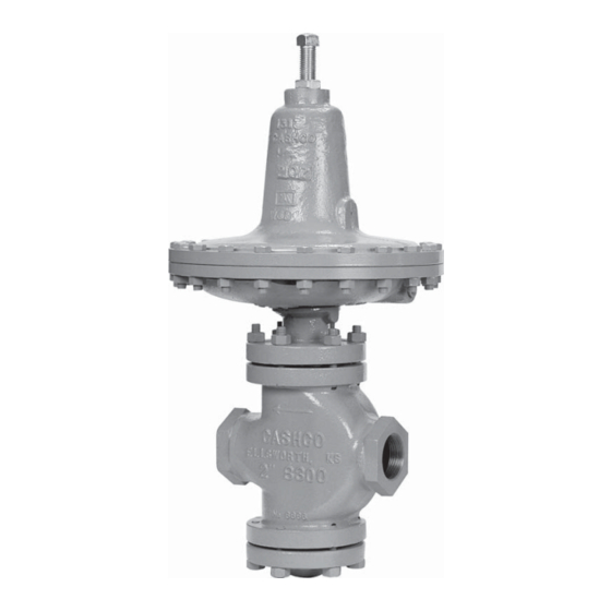
MODELS 8311HP AND 8311LP
l.
DESCRIPTION AND SCOPE
The Model 8311 is a high capacity back pressure / relief regulator with double seat design used to control upstream (inlet or P
pressure. Sizes are 1-1/2" (DN40), 2" (DN50), 2-1/2" (DN65), 3" (DN80) and 4" (DN100). With proper trim utilization, the unit
is suitable for liquid, gas eous, or steam service. Refer to Tech ni cal Bulletin 8311-TB for design conditions and selection recom-
mendations.
This is not a safety device and must not be sub sti tut ed for a code
approved pressure safety relief valve or rupture disc.
II. INSTALLATION
1.
An inlet block valve should always be installed.
2.
If service application is continuous such that shut down
is not readily accomplished, it is rec om mend ed that
an inlet block valve, outlet block valve, and a manual
bypass valve be installed.
3.
Pipe unions are recommended for NPT screwed in stal -
la tions to allow removal from piping.
4.
An inlet pressure gauge should be located ap prox i mate ly
ten pipe diameters upstream, and within sight.
5.
All installations should include a upstream re lief device
if the inlet pressure could exceed the pressure rating of
any upstream equipment or the maximum inlet pres sure
rating of the unit.
6.
Clean the piping of all foreign material including chips,
welding scale, oil, grease and dirt before in stall ing the
regulator. Strainers are recommended.
WARNING
The maximum inlet pressure is equal to 1.3 times the
larger number of the stated range spring on the nameplate,
and is the recommended "upper op er a tive limit" for the
sensing diaphragm. Higher pres sures could damage the
diaphragm. (Field hy dro stat ic tests frequently destroy
diaphragms. DO NOT HYDROSTATIC TEST THRU AN
IN STALLED UNIT; ISOLATE FROM TEST.)
INSTALLATION, OPERATION & MAINTENANCE MANUAL
BACK PRESSURE / RELIEF REG U LA TORS
SECTION l
CAUTION
SECTION II
Supply
@ P
1
SRV
PI
Model 8311HP or 8311LP
Back Pressure/Relief
Regulator
Recommended Piping Schematic
for Models 8311HP/LP
System
CAUTION
Installation of adequate overpressure pro tec tion is recom-
mended to pro tect the reg u la tor from overpressure and
all down stream equip ment from damage in the event of
regulator failure.
7.
In placing thread sealant on pipe ends prior to en-
gage ment, ensure that excess material is re moved and
not allowed to enter the regulator upon start-up.
8.
Flow Direction: Install so the fl ow direction match es the
arrow on the body. Install an external sensing line (1/2"
O.D. tubing min i mum) from the 3/8" NPT con nec tion
to a point up stream, pref er a bly at gauge location. If
regulator pipe line is ex pand ing to a larger pipe line,
always connect sensing line to the larger pipe line.
9.
For best performance, install in well drained hor i zon tal
pipe, properly trapped, if a steam service ap pli ca tion.
IOM-8311HP/LP-BASIC
12-13
)
1
Vent or
Reservoir
Bypass
Advertisement
Table of Contents

Related Manuals for cashco 8311LP


Summary of Contents for cashco 8311LP
- Page 1 INSTALLATION, OPERATION & MAINTENANCE MANUAL IOM-8311HP/LP-BASIC 12-13 MODELS 8311HP AND 8311LP BACK PRESSURE / RELIEF REG U LA TORS SECTION l DESCRIPTION AND SCOPE The Model 8311 is a high capacity back pressure / relief regulator with double seat design used to control upstream (inlet or P pressure.
-
Page 2: Principle Of Operation
10. Basic Regulator - (Refer to Figure 1): Regulator may 11. Regulators are not to be direct buried un der ground. be rotated around the pipe axis 360°. Rec om mend ed position is with spring chamber ver ti cal upwards. Orient 12. -
Page 3: Maintenance
SECTION VI VI. MAINTENANCE re move pressure plate nut (24) by rotating CCW (viewed from above). WARNING NOTE: Do not rotate the plug and stem assembly (12). The plug (12.1) and seat rings (10 & 11) have been me chan i cal ly lapped at the factory per ANSI SYSTEM UNDER PRESSURE. - Page 4 8311HP 45 ft-lbs (61 N-M) 5/8" Ø 10. Install plug and stem assembly (12) into body (1) 8311LP 45 ft-lbs (61 N-M) 1/2" Ø and place new body gasket (6) onto body (1). NOTE: Never replace bolting (29) (30) with just 11.
-
Page 5: Troubleshooting Guide
SECTION VII VII. TROUBLE SHOOTING GUIDE 1. Erratic operation; chattering. Remedies Possible Causes A. Oversized regulator; inadequate rangeability. A1. Check actual fl ow conditions, resize regulator for minimum and maximum fl ow. A2. Decrease regulator pressure drop; decrease inlet pressure by placing a throttling orifi... -
Page 6: Section Viii
Cashco, Inc. does not assume responsibility for the selection, use or maintenance of any product. Responsibility for proper selection, use and maintenance of any Cashco, Inc. - Page 7 Item No. Description Body Bonnet Bottom Flange Guide Bushing Stem Bushing Body Gasket Body Stud Body Stud Nut Upper Seat Ring Lower Seat Ring Valve Plug Assembly 12.1 Plug 12.2 Stem 12.3 Pin (Groove) Spring Chamber Diaphragm Case O-ring Bonnet Nut Pusher Plate Pusher Plate Gasket Stem Lock Nut...
- Page 8 Cashco, Inc. Cashco GmbH Cashco do Brasil, Ltda. P.O. Box 6 Handwerkerstrasse 15 Al.Venus, 340 Ellsworth, KS 67439-0006 15366 Hoppegarten, Germany Indaiatuba - Sao Paulo, Brazil PH (785) 472-4461 PH +49 3342 4243135 PH +55 11 99677 7177 Fax. # (785) 472-3539 Fax.
Need help?
Do you have a question about the 8311LP and is the answer not in the manual?
Questions and answers