
Related Manuals for Ecotec A4

Summary of Contents for Ecotec A4
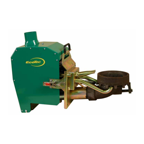
- Page 1 Operation and maintenance A4 Pellet burner 1-14-3009E 2005-03 MANUAL FOR A4 MODEL WITH MAX. OUTPUT 20 kW...
- Page 2 Store this manual somewhere easily accessiblefor future use. Please read through the manual carefully before starting up your EcoTec pellet system. The output of your pellet burner is calcu- lated according to the maximum quantity of pellets that can be fed in and burned in the...
-
Page 3: Table Of Contents
CONTENTS PAGE 4 OVERVIEW OF THE BURNER PAGE 5 OVERVIEW OF THE CONTROL PANEL PAGE 6 FUNCTIONAL DESCRIPTION PAGE 8 EASY TO MANAGE PAGE 9 SAFETY CHECKS/ALARMS PAGE 10 CONTROL SYSTEM / OPERATION PAGE 16 INSTALLATION PAGE 18 CONNECTION TABLE PAGE 20 TROUBLESHOOTING PAGE 22... -
Page 4: Overview Of The Burner
Burning cup Rotary arm 12 Internal fuel store Gear ring 13 Drive motor Primary ring 14 Level sensor (receiver), black Stop screws, burning cup 15 Level sensor (transmitter), white Primary air pipe 16 Connector Secondary air pipe 17 Feeder screw Hot-air ignition 18 Thermal contact Optical sensor... -
Page 5: Overview Of The Control Panel
Control box 3006 1 Start 7 Input Lambda probe (optional) 2 Stop 8 Input/Output multi-unit cable for the burner 3 Display 9 Input voltage 230/240 VAC 4 Control buttons for display manipulation 10 Output external feed 5 Input operational thermostat cable 11 Cover, terminal block 6 Input Max. -
Page 6: Functional Description
PELLET FIRING The burner can be adjusted for fuel with varying energy content. Pellet firing with EcoTec’s pellet burners is See fuel specification, page 23. extremely similar to oil firing. A pellet burner requires only slightly more main- The burner’s control unit is preprogram- tenance than an oil burner. - Page 7 NB AN ECOTEC BURNER MUST NOT BE COMBINED WITH ANY FEEDER SYSTEM OTHER THAN AN ECOTECORIGINAL FEEDER SYSTEM.
-
Page 8: Easy To Manage
EASY TO MANAGE Pellet burners from EcoTec are designed A thermal contact, located just outside in line with the main principles we are the boiler on the fuel feed pipe, detects any heat spreading back into the fuel accustomed to for oil-fired heating. The benefit of these main principles is con- feed pipe towards the internal store. -
Page 9: Safety Checks/Alarms
THE FOLLOWING MUST ALWAYS BE CONSIDERED AND CHECKED 1 The main power switch must always 3 The release gate’s wings must not be be on. damaged or discoloured and it must 2 Connections between burner and form a tight seal against the walls of external feeder system must be prop- the feed chamber. -
Page 10: Control System / Operation
Important information NB To avoid hazardous situations, the feed current must always be switched off before you touch any part of the equipment. Only authorised persons may carry out changes or repair the equipment. The manual is intended for authorised persons. It describes adjustments to many basic functions in the burner. - Page 11 In the menus, the cursor is used to highlight the command line that can be changed. When a parameter is changeable, the cursor changes from The control system may be in one of the following modes: Start, Operation, Standby or Stopped. When O is activated, XXX% (modulation) is shown in the top line of the display.
- Page 12 IGNITION SETTINGS OPERATING MODE Use the arrow keys to access the Ignition When the O -regulation is activated, the menu as per the structure tree on page 11. burner’s combustion fan and input feed screw are controlled in order to achieve set Optical sensor: Signal level when optical values for system temperature and percent- sensor indicates flame•...
- Page 13 Standby below: Indicates modulation in % -SETTINGS the burner must fall below in order to switch If O -regulation is activated, certain pa- to standby mode. It is also the level that rameters for this function can be adjusted must be exceeded for the burner to switch by the user.
- Page 14 FILL EXTERNAL SCREW WITH FUEL DESCRIPTION OF THE BURNER’S NORMAL IGNITION, OPERATING AND First fill the external screw. Remove the SHUT DOWN SEQUENCE downward hose from the burner. It may be useful to put a bucket under the hose. Factory setting Set the estimated number of minutes A non- running burner is indicated by using the parameter Manual time and...
- Page 15 • The burner fan has a delayed running EXTERNAL FEED time of 60 s. The external motor is controlled by the level sensor, the set run time coincides • At rest, no pilot light. Indicated with text with the internal motor Standby •...
-
Page 16: Installation
(static electricity) protection for the printed circuit card. If this part is opened without the approval of EcoTec, ALL guarantees HUVUDBRYTARE will cease to be valid. (Pelletsbrännare) The unit is fitted on a vertical wall using three screws. - Page 17 Connecting an alarm unit THE MAIN SWITCH MUST A buzzer or light is connected to the ONLY BE SWITCHED OFF IN CONNECTION potential-free contact, connection termi- WITH SERVICING AND MAINTENANCE. nal board K1 and K2. REMEMBER TO SWITCH The standard units are adapted for a ON THE MAIN SWITCH WHEN drive voltage between 12 and 24 VDC.
-
Page 18: Connection Table
CONNECTION TABLE FOR CONTROL BOX 3006 Control cabinet Max. thermostat Lambda probe External screw Operating temperature Incoming feed Multi-unit cable... - Page 19 *) M:x = Multiconductor for burner T:x = Thermostat cable for max. thermostat S:x = Operating temperature Burner Black Burner fan Black Red + Level sen.trans Black - Red + Level sen.rec. Black - Brown Optical sensor Brown Internal motor Blue Thermo gauge Blue...
-
Page 20: Troubleshooting
TROUBLESHOOTING The alarm text: * Max thermostat * The majority of all faults that may arise CHECK: If the boiler’s maximum thermo- are a direct result of defects in the pellet stat has been tripped. quality, and its handling or storage. Therefore, check your supply carefully. - Page 21 CHECK: Start the burner and check that The alarm text: * Error Ext. Feed* both the drive motor and outfeed shaft This fault is due solely to a lack of fuel in and screwshaft turn round in the burn- the burner’s internal store. ing cup.
-
Page 22: Maintenance
MAINTENANCE • Be extra careful after a new delivery • Check the optical sensor and clean as or change of pellets. required. • When checking the burning cup, the • Check release gate’s seals on the burner should always be removed. burner’s internal store and clean as (Check that the three stop screws that required. -
Page 23: Advice On Fuel Pellets
APPROVED FUEL SPECIFICATION The EcoTec pellet burner is designed to be able to burn most types of pellet fuel. WEIGHT 600 – 750 kg/m ENERGY CONTENT 4.7 –... -
Page 24: Guarantee And Complaints
– costs caused as a result of the product being connected to a product not approved for connection by EcoTec. OTHER This guarantee does not affect the purchaser’s rights in accordance with the Consumer Purchases Act, nor... -
Page 25: Operation Log
OPERATION LOG DATE MEASURE... - Page 26 OPERATION LOG DATE MEASURE...
- Page 27 OPERATION LOG DATE MEASURE...
- Page 28 If you have any views on our products, please ring, write or fax us. Sahlins EcoTec AB Box 2103, SE-511 02 Skene, Sweden Tel. +46 0320-20 93 40. Fax +46 (0)320-421 60 info@ecotec.net, www.ecotec.net.
Need help?
Do you have a question about the A4 and is the answer not in the manual?
Questions and answers