Table of Contents
Advertisement
Quick Links
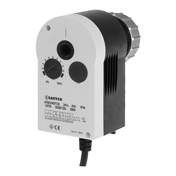
AVM 104S...115S: Valve drive with Sauter Universal Technology SUT
For controllers with continuous output (0...10V) or switched output (2- or 3-point control). To operate
through valves or three-way valves in series VXN/BXN, VUD/BUD, VUE/BUE. Choice of characteristic
(linear/equal-percentage) can be set on the actuator.
Two-part housing of fire-retardant plastic, lower part in black, upper part in yellow. With stepping motor,
SUT electronic control unit and maintenance-free gears. Fixing bracket of plastic and cap nut of brass
for fitting the valve. Assembly with the valve is practically automatic. Direction of operation can be
changed at the cable. Electronic, torque-based cut-out via stops on either the actuator or the valve;
automatic adaptation to the valve's stroke. Coding switches for selecting characteristic and running
time. Disengageable gears for positioning the valve by hand (Allen key enclosed with product). Power
cable 1,2 m long, 5× 0,5 mm². Fitting position: anywhere from vertical to horizontal, but not upside down.
Type
Running time
s
For valves with linear characteristic, can be switched over to equal-percentage
AVM 104S F132
35/65/130
AVM 114S F132
60/120
For valves with equal-percentage characteristic, can be switched over to linear
AVM 105S F132
35/60/120
60/120
AVM 115S F132
Positioner
1)
Control signal
0...10V, R i > 100 kΩ
Positional feedback signal
0...10V, load > 10 kΩ
± 20%, 50...60 Hz
Power supply
24V∼
2)
24V=
+ 20% / - 10%
AVM 105S F132
4,8 W
AVM 115S F132
4,9 W
Max. media temperature
100 °C
Permissible amb. temp.
–10...55 °C
Ambient humidity
5...95 %rh
without condensation
For control valve type KTM512 / TA-Regulator DN 15...50
Type
Running time
s
AVM 115S F901
80/160
Deviation from standard type: inverse scale therefore inverse direction of operation. Adaptor for
control valve available on the valve or from TA-Regulator, stating reference no. 52 757 003.
Accessories
0313529 001*
Split-range unit for setting sequences; to be fitted in separate distribution box as
per MV 505671
0372145 001*
Single auxiliary change-over contacts
0372145 002*
Double auxiliary change-over contacts
0372249 001*
Intermediate piece required for media temperature >100 °C
(recommended for temperature < 10 °C); MV 505932
0372273 001*
Adaptor for Siemens VVG / VXG 44 and 48 valves; MV 505848
4)
0372286 001
Potentiometer
4)
0372286 002
Potentiometer
4)
0372286 003
Potentiometer
0372462 001
CASE Drives PC Tool for configuration of actuators per computer; MV 506101
*)
Dimension Drawing or wiring diagram are available under the same number
1)
Also for 2-point or 3-point. depending on type of connection
2)
24V = for input signal of 0...10V only on AVM 1 . 4; on AVM 1 . 5S for all functions.
3)
Fully variable from 0...100%; max. loading 5 (2) A. 24....230V
4)
Only one potentiometer or one set of auxiliary contacts can be fitted to each drive!
5)
Maximum stroke of drive = 10,0 mm
5)
Stroke
Pushing force
mm
N
7,5
250
7,5
500
8,0
250
8,0
500
Starting point U
Control span ΔU
Switching range X
Protection (horizontal)
Protection class
8,5 VA
Response time
8,7 VA
Dimension drawing
Fitting instructions 1 . 4S MV 505790
Fitting instructions 1 . 5S MV 506065
Declaration on materials
Stroke
Pushing force
mm
N
10,0
500
3)
; MV 505795
3)
; MV 505795
130 Ω; MV 505795
1000 Ω; MV 505795
5000 Ω; MV 505795
Power
Weight
kg
24 V~/=
2)
0,7
24 V~/=
2)
0,7
24 V~/=
0,7
24 V~/=
0,7
0 or 10V
0
10V
200 mV
sh
IP 54 as per EN 60529
III as per IEC 60730
1)
200 ms
A09673
M09743
MD 51.362
Power
Weight
kg
24 V~
0,7
Sauter Components
51.362/1
M
Y07552
100 %
0 %
0 V
Output signal y
10 V
B07650
7151362003 03
Advertisement
Table of Contents

Related Manuals for sauter AVM Series


Summary of Contents for sauter AVM Series
- Page 1 51.362/1 AVM 104S…115S: Valve drive with Sauter Universal Technology SUT For controllers with continuous output (0...10V) or switched output (2- or 3-point control). To operate through valves or three-way valves in series VXN/BXN, VUD/BUD, VUE/BUE. Choice of characteristic (linear/equal-percentage) can be set on the actuator.
- Page 2 Other switches enable the running times to be set. These can be applied irrespective of whether the 2-point. 3-point or the continuous function has been chosen. Sauter Components 7151362003 03...
- Page 3 Effective on valve character. curve for drive curve for valve curve Stroke 1 2 3 Signal Stroke Signal Stroke 1 2 3 Stroke Signal Signal Stroke 1 2 3 Signal Stroke Signal = factory setting B10701 Sauter Components 7151362003 03...
- Page 4 Effective on valve character. curve for drive curve for valve curve Stroke 1 2 3 Signal Signal Stroke Stroke 1 2 3 Signal Stroke Signal Stroke 1 2 3 Signal Signal Stroke = factory setting B10704 Sauter Components 7151362003 03...
- Page 5 To ensure that the settings with CASE Drives cannot be overwritten, the coding switch should be removed before setting values through CASE Drives (special tool included). Sauter Components 7151362003 03...
- Page 6 Standstill 0,35 Operating 4,25 Standstill 0,35 AVM 115S F132 Operating Standstill 0,35 0,75 Operating 2,25 Standstill 0,35 0,75 CE conformity EMC directive 2004/108/EC Machine directive 98/37/EEC (II B) EN 61000-6-1 EN 1050 EN 61000-6-3 EN 61000-6-4 Sauter Components 7151362003 03...
- Page 7 51.362/7 AVM 104S...115S Wiring diagram RD = red BN = brown BK = black BU = blue GY = grey A10450 Sauter Components 7151362003 03...
- Page 8 RD BN BK RD BN BK GN GY VT MM 01/02 A10183 A09782 Printed in Switzerland Right of amendment reserved N.B.: A comma between cardinal numbers denotes a decimal point © Fr. Sauter AG. CH-4016 Basle 7151362003 03 Sauter Components...
Need help?
Do you have a question about the AVM Series and is the answer not in the manual?
Questions and answers