Table of Contents
Advertisement
Advertisement
Table of Contents

Summary of Contents for SAC T120
- Page 1 T120 USE AND MAINTENANCE INSTRUCTIONS Edition 12/2003 Code 62900306...
-
Page 3: Table Of Contents
T120C INTRODUCTION ........... . MACHINE DESCRIPTION . - Page 4 T120C 3.3.3 Machine cleaning ............MACHINE CONNECTION WITH THE POWER SOURCES .
- Page 5 T120C SHAFT MACHINING PROCEDURES ........4.9.1 Milling with the curved guide .
- Page 6 T120C TABLES INDEX Table 1: Safety plates ............. Table 2: Machine weight .
-
Page 7: Introduction
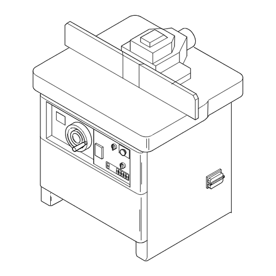
T120C INTRODUCTION MACHINE DESCRIPTION Vertical single shaft milling machine, for machining wooden pieces by chip removal with rotary tool installed on the shaft. The machine has manual feeding, with a single vertical shaft, which can be fixed or in- terchangeable, with fixed position during the machining and a horizontal supporting plane, fixed during the machining. -
Page 8: Machine Identification
T120C MACHINE IDENTIFICATION 1.3.1 Machine identification The machine is identified by the writings shown on the plate (Fig. 1) placed on the base- ment as indicated in Fig. 2. ’ ’ Fig. 1: Machine identification plate. Nr./Seriennummer/Serial No. No. d’immatriculation #f8 massimo utensile ’... -
Page 9: Service Recommendations
T120C • Machine model • Machine serial number • Manufacturing year 1.3.3 Service recommendations When preparing this instruction handbook, all the operations involved in the routine maintenance have been considered. We recommend you not to make any repair or intervention not indicated in this hand- book. -
Page 10: Final Test Report
T120C 1.3.4 Final test report The factors for the final test of the machine geometry are referred to the norm ISO 7009, and particularly: Machining table flatness Tolerance Longitudinal (A) 0.15 mm Diagonal (A) 0.25 mm Transversal (B) 0.15 mm Longitudinal rectilinearity of the machining guide shoulders Tolerance Wood... - Page 11 T120C Flatness of the tool supporting surface Tolerance 0.020 mm Perpendicularity of the tool-holding shaft to the machining table Tolerance 0.10 mm Flatness of the spacer supporting plane Tolerance 0.20 mm Seller’s/dealer’s stamp...
- Page 12 T120C...
-
Page 13: Working Safety
T120C WORKING SAFETY GENERAL SAFETY RULES The machine operator and the person in charge must read this instruction handbook carefully and completely before executing any operation on the machine. Keep this handbook close to the machine. The manufacturer is continuously improving the products, so some machine compo- nents may possibly change. -
Page 14: Safety Plates
9000 10000 DANGER HIGHT VOLTAGE T120 sueri Fig. 3: Position of the safety plates Safety plates in English have been positioned on the machine. Plates in Spanish are supplied as well, to be positioned on the machine in case of need for the operator. - Page 15 T120C...
-
Page 16: Symbols
T120C Table1: Safety plates 2.1.3 Symbols To point out the handbook sections concerning personal safety, the following symbols have been used in the USE AND MAINTENANCE operations of the machine: ATTENTION Information or procedure that, if not carefully followed, could cause death or serious personal injuries. -
Page 17: Machine Correct And Improper Use
T120C NOTE Important information or procedure It is recommended to use the personal protection devices for the eyes. It is recommended to use the personal protection devices for the ears. It is recommended to use the personal protection devices for the hands. It is recommended to use the personal protection devices for the lower limbs against the squeezing due to falling pieces during the operation. -
Page 18: Individual Risk Factors
T120C Fig. 4: Working place INDIVIDUAL RISK FACTORS Some clothes or accessories worn by the operator can cause accidents. It is advisable to avoid wearing dangerous objects, such as: rings, watches, bracelets, large-sleeved overalls, not perfectly fastened belts, ties and, generally, anything sticking out of the person that may be grasped by a moving part of the machine during its operation: people with long hair should keep it gathered on the back of the neck, and possibly wear a cap. -
Page 19: Protection And Safety Devices
T120C advisable to check the correct grounding of the machine; these steps must be recalled to the specialized technician carrying out the electrical connection. • Before carrying out any maintenance on the machine, switch and cut it off from power sources, set the main switch on zero and lock it. •... - Page 20 T120C min - - 1 3000 4500 6000 8000 10000 Fig. 5: Protection and safety devices emergency push button lockable main switch self-braking motor with intervention lower than 10 s; interlocked front cover; it stops the spindle rotation when opened guard interlock micro-switch machining guide guard - chip conveyor for the guide machining...
-
Page 21: Residual Risks
The acoustic power levels have been measured according to the measuring method using the developed surface shown in EN ISO 3746: 1995. The acoustic emission pressure level at the operator’s seat has been measured ac- cording to EN ISO 11202: 1996. T120 Empty without Operating with suction... -
Page 22: Dust Emission Levels
T120C • correct choice of the tool • correct choice of the feeding speed • maintenance on the tools and on the machine • correct use of the personal protection devices 2.8.2 Dust emission levels The dust emission level in the place of work is [0.17](mg/m of air). -
Page 23: Machine Installation
T120C MACHINE INSTALLATION HANDLING - TRANSPORT - STORAGE Model T120 Weight kg Table2: Machine weight 3.1.1 Lifting method Use lifting means with min. capacity of 1,000 kg. Fig. 6: Machine lifting with lift truck. When using the lift truck, place some anti-slip material between the forks and the ma-... -
Page 24: Storage
T120C min 3000 - - 1 4500 6000 8000 10000 Fig. 7: Machine handling by crane. When using lifting belts or ropes, they must have a suitable capacity and being posi- tioned as indicated in Fig. 7; the machine parts touching the lifting means must be pro- tected. -
Page 25: Positioning
T120C POSITIONING 3.2.1 Positioning and foundations Place the machine on a reinforced concrete board with a thickness of about 150 mm, properly levelled and sized a little larger than the machine overall dimensions. It is not necessary to fasten the machine to the floor. Make the machine stable by levelling it to the floor;... -
Page 26: Machine Installation
T120C 3.3.2 Machine installation The machine is delivered with some details removed; they must be installed before starting the machine up: • the upper cover (52) of the machining guard (57) at the guide; remove the sup- ports (58) and fit them in the cover side pins, then fasten the supports together with the cover to the guard (57);... -
Page 27: Machine Cleaning
T120C 3.3.3 Machine cleaning Before starting to work, degrease carefully the working areas and the guards with a suitable and safe thinner. MACHINE CONNECTION WITH THE POWER SOURCES 3.4.1 Connection with the electric system All the operations concerning the electrical connection must be made by skilled person- nel in compliance with the regulations in force. -
Page 28: Check Of The Rotating Direction
T120C DANGER DO NOT REMOVE WHEN REMOVING THE FENCE SAFETY GUARDS. MAKE SURE TO FIT THE PROPER SAFETY GUARD FOR ANY KIND OF MACHINING min - - 1 3000 4500 6000 8000 10000 Fig. 10: Terminal board. 3.4.2 Check of the rotating direction Check the rotating direction of the spindle shaft starting the machine as described in §... - Page 29 T120C The suction pipes, if in plastic, must be fire retardant. The dust emission in the environment can be reduced by: • maintaining the tools and the machine; • maintaining the suction system keeping the filters efficient; Fig. 11: Suction inlets Features of the suction inlets supplied with the machine ∅...
- Page 30 T120C...
-
Page 31: Machine Start-Up And Use
T120C MACHINE START-UP AND USE CONTROL LIST AND FUNCTIONS Fig. 12: Machine controls 1 handwheel for the spindle vertical adjustment; 2 retractable folding lever; 3 indicator for the vertical incremental position of the shaft;... -
Page 32: Spindle Positioning
T120C 4 motor brake IN/OUT switch; 5 emergency stop push button; 6 overload cutout main switch; 7 spindle motor standard stop push button; 8 push button for enabling the shaft rotation direction reversal; 9 rotary switch for selecting the spindle rotation direction; 12 locking lever for the vertical movement of the spindle turret;... -
Page 33: Tool Handling
T120C For safety reasons, each tool is suitable for working at a max. speed; this value is indi- cated by the manufacturer on the tool surface and indicates the max. revolution number the tool can follow. When purchasing the tools the carpenter must ask his tool supplier for tools with the following features: •... -
Page 34: Initial Adjustments And Outfit
T120C Should the tool be damaged, balance it immediately. INITIAL ADJUSTMENTS AND OUTFIT 4.5.1 Installation of the interchangeable spindle To install the interchangeable spindle, operate as follows: • by the handwheel (1) lift the spindle completely and lock the spindle-holding shaft rotating the knob (13) in the position A (Fig. -
Page 35: Removal Of The Interchangeable Spindle
T120C Fig. 15: Interchangeable spindle • fit the locking cone of the spindle (19) in the corresponding seat of the spindle- holding shaft (20) and tighten the locking ring nut (21) rotating it clockwise to- gether with the spindle; • using the supplied wrench (22) tighten the ring nut (21) checking the distances indicated in Fig. -
Page 36: Tool Installation On The Spindle
T120C 4.5.3 Tool installation on the spindle This operation must be made every time the tools are to be installed or replaced on the spindle shaft: • by the handwheel (1) lift the spindle completely and lock the spindle-holding shaft rotating the knob (13) in the position A (Fig. 14); •... - Page 37 T120C Fig. 16: Tool installation • tighten the nut (26) effectively by the supplied wrench (30); • release the spindle-holding shaft rotating the knob (13) in position B (Fig. 14).
-
Page 38: Selection Of The Tool Rotating Speed
T120C 4.5.4 Selection of the tool rotating speed The tool max. speed must be lower than the max. one allowed by the manufacturer, and anyway not lower than 35 m/s, to avoid the risk of piece rejection, and not higher than 80 m/s, to avoid the danger of tool damaging. - Page 39 T120C Table5: Selection of the tool rotating speed Use example of Table 5: Miller diameter = 200 mm Available speeds: 3000, 4500, 6000, 8000, 10000 min To define the operating speed intersect the line indicating the cutter diameter with the spindle rotation speed column, in this case the choice is between 4500 and 6000 min 3000 min is too low (surface speed lower than 35 m/s), 8000 min...
- Page 40 T120C Fig. 18: Belt position and revolution number. 4.5.4.1 Belt positioning on the races, Fig. 19 • release the motor support rotating the lever (15) counterclockwise and loosen the belt operating the lever (16) rightwards; • position the belts on the chosen race, referring to Fig. 18; •...
-
Page 41: Safety Operating Procedures
The max. dimensions of the pieces being machined (Table 6) relate to the piece bal- anced on the roller plane before, during and after the machining; always check this condition, both for profiling and tenoning operations, so as to avoid sudden piece movements due to instability. T120 Max. length Min. length Max. width Min. -
Page 42: Machine Adjustment And Installation
T120C For non-rectilinear pieces, as well, use templates to support and machine them with full safety. 4.6.2 Machine adjustment and installation Before any adjustment or maintenance the machine must be cut off. 4.6.3 Tool adjustment on the machine Templates and guides must be used for positioning the tools on the machine to ensure accuracy and reduce the need for adjusting the machine. -
Page 43: Guide Machining With Cutting Through All The Piece Length
T120C Each machining must be separately considered and the most practical guard for the peculiar machining must be selected. The min. hole in the table, too, shall depend on the kind of tool, on the blade projection and on the height of the cutter positioning. The supplied reduction rings are very useful for getting a hole as small as possible. -
Page 44: Shaft Machining
T120C A template is therefore necessary, as well as a protecting device repairing the cutter as much as possible. Two retainers must also be used at the two ends. The template must enable a piece fast and accurate positioning, as well as being tightly hold. -
Page 45: Operating Cycle
T120C OPERATING CYCLE 4.7.1 Spindle start To start the spindle, operate as follows: Fig. 20: Control panel • Carry out the checks indicated at § 4.3; • power the machine turning the knob (18); • set the switch (4) in brake release position; •... - Page 46 T120C • A dummy guide must be used as often as possible for reducing the distance between cutter and guides: a sample is supplied together with the machine. Fig. 21 gives the dimensions of a dummy guide, a sample of which is supplied together with the machine.
- Page 47 T120C Fig. 23: Pusher 4.7.2.1 Guide adjustment Fig. 24: Guide machining guard...
-
Page 48: Pressing Device Use For The Guide Machining
T120C 23 - Infeed guide locking lever 24 - Outfeed guide locking lever 27 - Infeed guide 28 - Outfeed guide 34 - Infeed guide shoulder locking lever 35 - Outfeed guide shoulder locking lever 36 - Infeed guard locking lever 37 - Outfeed guard locking lever 38 - Infeed shoulder adjustment handwheel 39 - Outfeed shoulder adjustment handwheel... -
Page 49: Use Of The Machining Guide With Three Positions (Optional)
T120C Adjust the vertical pressing device (59) on the piece height, acting on the screw (69), and outside the tool cutting circumference, acting on the screw (67) and lock it in position. Adjust the front protection (63) as for its height making it slide vertically; and ac- cording to the tool diameter placing it inside the holes made on the shoulders (27 - 28). - Page 50 T120C 28 - Outfeed guide 36 - Infeed guard locking lever 37 - Outfeed guard locking lever 38 - Infeed shoulder adjustment handwheel 39 - Outfeed shoulder adjustment handwheel 40 - Upper cover locking pin 52 - Upper cover 53 - Outfeed shoulder clearance adjusting screw 54 - Incremental decimal rod for infeed shoulder adjustment handwheel 55 - Incremental decimal rod for outfeed shoulder adjustment handwheel 56 - Outfeed shoulder position millimeter rod...
-
Page 51: Guide Machining Procedures
T120C • lock the lever (37); • loosen the lever (36); • rotate the handwheel (39), (clockwise rotation: the guide moves backwards, counterclockwise rotation: the guide moves forwards). Simultaneous micrometric adjustment of the infeed guides (27) and outfeed guides (28), position C: •... -
Page 52: Guide Machining With Cutting Through All The Piece Length
T120C 4.8.1 Guide machining with cutting through all the piece length Such a machining is made using a straight guide in most of the cases; the pieces have a rectangular section through all their length. The pieces can be guided by the angle formed by table and guide. The vertical and horizontal pressing devices are arranged for forming a tunnel through which the piece can be guided;... - Page 53 T120C Fig. 27: Installation of a guard for machining with curved guide 1 - Install the cutter on the cutter-holding spindle; 2 - choose the guide plate with shape (a) or (b) and screw it on the support plate; 3 - install the multi-curve servo-cutter on the cutter-holding spindle choosing the spac- ing rings between cutter and servo-cutter so that the cutter can freely rotate, and tighten completely the nut or the locking screw of the cutter on the spindle;...
- Page 54 T120C Fig. 28: Protecting device for the shaft machining 7 - loosen the thumbscrews on both sides; 8 - move the casing upper part forwards until it sufficiently covers the cutter (c: position for manual infeed milling, d: position for feeder infeed milling); 9 - fasten the guard brushes;...
- Page 55 T120C the two cover guide components descend, so as to get the wished pressure against the piece, and tighten the thumbscrews carefully; 12 - to aid the piece guide, install a two-roller pressing device (optional); 13 - position the guard brushes so that they cover the movement area of the curved piece.
-
Page 56: Milling With Inlet Ring
T120C 4.9.2 Milling with inlet ring The sequence of the steps to be made refers to the number sequence inside the follow- ing figures. Fig. 30: Installation of a guard for machining with inlet ring 1 - Install and fasten the wished cutter and the corresponding inlet ring on the cutter- holding spindle;... - Page 57 T120C 2 - fasten the casing on the machine table to cover the cutter; 3 - loosen the thumbscrew until you can push the infeed strip, rotating it by 90_ back- wards; 4 - position the infeed strip at the height of the inlet ring, pressing it against the inlet ring, and tighten the thumbscrew carefully.
- Page 58 T120C Fig. 32: Accessories for the guide machining...
-
Page 59: Tenoning Procedure With Sliding Table
T120C 4.10 Tenoning procedure with sliding table 4.10.1 Tenoning sliding table Fig. 33: Sliding table locking device Vise Vise operating lever Vise vertical locking lever Vise horizontal locking lever Piece sloping rest Rest locking lever... - Page 60 T120C Fixed guard and vise supporting pin Fixed guard 10 Fixed guard locking screw 11 Reference ledges for piece length 12 Ledge locking knob 13 Splinter--proof device 14 Rule 15 Rule extension The square enables straight tenoning or tenoning sloped from -60° to +60°. Fig.
-
Page 61: Adjustment Of The Protecting Device For Tenoning Operations
T120C For using the sliding table operate the device 1 pulling the relevant knob downwards. 4.10.2 Adjustment of the protecting device for tenoning operations Fig. 35: Remove the vertical and horizontal pushers; release the guides 26 and 27 and open them; open the guard 25 acting on the safety pin 24 to release it;... -
Page 62: Tenoning Of Straight Pieces
T120C 4.10.3 Tenoning of straight pieces Follow the indications of par. 4.10.2; position the belt at the lowest speed; position the spindle vertically; then, referring to Fig. 33 proceed as follows: lay the wooden piece on the guide 14; adjust the position of the reference ledges 11 to determine the tenoning depth; loosen the vise 2 by the lever 4 until the cap touches the piece and lock in this posi- tion;... - Page 63 T120C start the spindle; make the piece touch the tool by pushing the sliding table with the hands as shown; at the end of the machining switch the spindle motor off. Fig. 36:...
- Page 64 T120C...
-
Page 65: Maintenance
T120C MAINTENANCE MAINTENANCE AND SAFETY A careful maintenance makes the machine life longer and keeps the machining fea- tures unchanged. An important safety factor for the machine and the operator is a gen- eral accurate cleaning of the machine and the surrounding area; in the evening, at the end of the works, it is advisable to clean by means of a vacuum-cleaner. -
Page 66: Safety Measures
T120C Do not use the machine if the protection and/or safety devices are not efficient. Before any maintenance intervention, set the main switch to zero and warn about the machine stop by a sign. 5.1.1 Safety measures Periodically press the emergency push button to make sure it is efficient. Check if the motor brake stops the shaft for a max. -
Page 67: Self-Braking Motor
T120C SELF-BRAKING MOTOR Every 2 months or 200 stops, periodically check and adjust the braking electro-magnet- ic device, as the motor braking time must be kept under 10 s. Detecting longer braking times it is necessary to adjust the entrefer or replace the brake friction material. -
Page 68: Replacement Of The Movable Anchor - Brake Disk (12)
T120C Fig. 38: Light self-braking motor 5.3.2 Replacement of the movable anchor - brake disk (12) • Remove the air conveyor (18); • loosen the locknut (16) for adjusting the braking torque; • remove the washer (15); • pull the cooling and braking fan (13) out; •... -
Page 69: Replacing The Electro-Magnet (11)
T120C 5.3.3 Replacing the electro-magnet (11) • Open the terminal board cover (7) and disconnect the electro-magnet (11) from the feeder-rectifier (8); • remove the air conveyor (18); • loosen the locknut (16) for adjusting the braking torque; • remove the washer (15); •... - Page 70 T120C...
-
Page 71: What You Must Do If
T120C WHAT YOU MUST DO IF... FOREWORD The machine transport, unloading and positioning, an incorrect use or a poor mainten- ance may result in problems that can be solved according to the following points. Symbol key: Interventions that the user can do. Interventions that must be made by the skilled technical staff of the (inner or outer) service. -
Page 72: The Spindle Motor Overload Cutout Has Intervened At The Switching-On
T120C 6.1.3 The spindle motor overload cutout has intervened at the switching-on CAUSE REMEDY The clockwise rotation speed has been se- Press the push button to enable the clock- lected wise rotation before starting the spindle Open front cover Close the cover 6.1.4 The overload cutout of the spindle motor has intervened CAUSE... -
Page 73: Technical And Environmental Data
T120C TECHNICAL AND ENVIRONMENTAL DATA TECHNICAL DATA T120 STANDARD FEATURES Spindle start direct remote starter with push button Motor magneto-thermal protection Automatic motor brake Speed reversal Grooving on table Spindle rotation speed Rings on table Front handwheel for shaft vertical positioning... - Page 74 T120C T120 Fixed spindle shaft vertical stroke Distance between fixed shaft stop and machining table -171 Inner diameter of the rings on the table 72 - 108 - 152 - 224 - Max. diameter of the tools for profiling Max. dimensions of the tool retracting under the table...
- Page 75 T120C T120 PACKING – TRANSPORT Overall dimensions for the transport: Width 1300 Length Height 1190 Case packing dimensions: Width 1460 Length Height 1050 Weight Weight with package ELECTRICAL DATA Spindle motor power 6.6 / 9 Three-phase voltage 220/400 Connection voltage...
- Page 76 T120C T120 Additional interchangeable spindle MK5 Table extension, with emergency push button, up to: 1750 Table extension, with emergency push button, up to: 2400 Aluminum shoulder for machining guide Machining guide (guard) with 3 adjustments: simultaneous drive of the 2 shoulders;...
-
Page 77: Overall Dimensions
T120C OVERALL DIMENSIONS min - -1 3000 4500 6000 8000 10000 1300 Fig. 39: Overall dimensions... - Page 78 T120C...
- Page 80 SUERI ALFREDO S.p.a. Via Carpi Ravarino, 115 41010 Limidi di Soliera (MO) - - ITALY tel. +39 059 855711 - - fax +39 059 855757 e- -mail sac@sacsueri.com http://www.sacsueri.com...
Need help?
Do you have a question about the T120 and is the answer not in the manual?
Questions and answers