Table of Contents
Advertisement
Quick Links
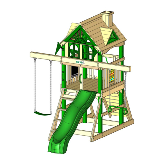
The Five Star Space Saver
Timber Shield Post Option
BOXES: 380
*51-0094-W*
51-0094-W
™
™
play sets
play sets
Model: 383
(BOXES: 380-1, 380-2, 383, 320
& Slide Box)
Copyright © 2018 Gorilla Playsets
All Rights Reserved
190 Etowah Industrial Court
Canton, GA 30114
www.gorillaplaysets.com
™
™
playsets
playsets
Advertisement
Table of Contents

Related Manuals for Gorilla Playsets Five Star Space Saver 383


Summary of Contents for Gorilla Playsets Five Star Space Saver 383
- Page 1 The Five Star Space Saver Timber Shield Post Option Model: 383 BOXES: 380 (BOXES: 380-1, 380-2, 383, 320 & Slide Box) Copyright © 2018 Gorilla Playsets All Rights Reserved *51-0094-W* 190 Etowah Industrial Court Canton, GA 30114 www.gorillaplaysets.com 51-0094-W...
- Page 2 Please inspect and inventory all parts immediately upon accepting delivery. Use the inventory pages in the manual to make sure you have received all necessary parts. The quickest method to get any parts that are missing or damaged is to use our “Quick Response Center”...
- Page 3 This decision is subject to verification of the defect, which, at Gorilla’s discretion, may be accomplished by submitting photographs or by delivery of the defective part to Gorilla Playsets • 190 Etowah Industrial Ct. • Canton, GA 30114 • 1-800-882-0272 Monday to Friday 9AM-5PM EST. Any warranty claim must include proof of purchase, including the date of purchase.
- Page 4 Gorilla shall not be liable for incidental, indirect or consequential damages or injuries that result from building and/or playing on our play sets. Adult supervision is recommended anytime a play set is being used. WEIGHT LIMITS FOR GORILLA PLAYSETS • FORT PLATFORMS: 800 LBS. TOTAL WEIGHT • SWING BELT: 225 LBS.
- Page 5 Product registration - the five star sPace saver - Gorilla Playsets manufactures ™ 3 Easy Ways To REgisTER the finest quality products that are designed for outstanding Complete the online registration form at: oPtion 1 http://www.gorillaplaysets.com/register strength and durability. We back...
- Page 6 THIS PAGE INTENTIONALLY LEFT BLANK...
- Page 7 IMPORTANT – PLEASE READ Congratulations! You have just purchase one of the finest residential wooden swing sets available today. As with any wooden product that spends its entire life outside, in varying elements, it is important to know what to expect with your new swing set so that your family can enjoy it for many years.
- Page 8 Please review these safety rules regularly with your children. WARNING: Children must NOT use this play set until it has been completely assembled and inspected by an adult to ensure it has been properly installed. Gorilla Playsets 190 Etowah Industrial Court Canton, GA. 30114...
- Page 9 Model: 383 Timber Shield Post Option BOXES: 380 (BOXES: 380-1, 380-2, 383, 320 & SLIDE BOX) REV: 6.14.2018...
-
Page 10: Table Of Contents
TABLE OF CONTENTS Safety Guidelines………………………………………..……......Pages 3-6 Leveling Fort, General Information and Definitions……………………....Pages 6-8 How to install T-nuts, Board Identification, Predrill Lag Screw Directions and Swing Beam Loading………………………............Pages 9-13 Site Plan, Required Tool and Material List, Kit Contents…..………...…..Pages 14-15 Hardware, Lumber and Accessory Checklists…………………………..……...Pages 16-31 Adding T-Nuts to Corner Posts and Framing Left/Right Sides..……...….. - Page 11 Safety and Maintenance Tips for Your New Play Set: NOTE: Your children’s safety is our #1 concern. Observing the following statements and warnings reduces the likelihood of serious or fatal injury. Please review these safety rules regularly with your children. •...
- Page 12 Safety and Maintenance Tips for Your New Play Set: (continued) Playgrounds should be inspected on a regular basis. If any of the following conditions are noted, they should be removed, corrected, or repaired immediately to prevent injuries. • Hardware that is loose, worn or that has protrusions or projections. •...
- Page 13 Play Set Surfacing Recommendations: Below are some of the recommendations that the U.S. Consumer Product Safety Commission (CPSC) offers from its Handbook for Public Playground Safety. The guide can be downloaded in full at www.cpsc.gov/PageFiles/122149/325.pdf 1. Protective Surfacing - Since almost 60% of all injuries are caused by falls to the ground, protective surfacing under and around all playground equipment is the most critical safety factor on playgrounds.
- Page 14 2. Fall Zones - A fall zone, covered with a protective surfacing material, is essential under and around equipment where a child might fall. This area should be free of other equipment and obstacles onto which a child might fall. Stationary climbing equipment and slides should have a fall zone extending a Minimum of 6’...
- Page 15 General Info to Review Before Installation • Depending on your experience, assembly of the playset can take as little as 6 hours up to 24 hours, depending on size, after inventory of parts; therefore, we recommend you set aside a full two days for assembly. •...
- Page 16 This page is a list of definitions and explanations used throughout our instructions to aid you in the assembly of your play set. Offset Holes- Throughout the installation procedures we will refer to parts with offset holes. This refers to the orientation of the holes on the board. An offset hole is one that is closer to one side than it is the other or in other words, it is not centered on the board.
- Page 17 Common Installation Practice Installing T-nuts When installing T-nuts into the wood, use a smooth faced hammer to set the face of the T-nut flush into the wood. Corner Post T-nut Insert the barrel of the T-nut into the predrilled hole. Using a smooth faced hammer, drive the T-nut until the face of the T-nut is flush to the wood.
- Page 18 HOW A T-NUT WORKS THE FIRST STEP IN OUR ASSEMBLY INSTRUCTIONS IS TO INSERT T-NUTS INTO THE CORNER POSTS. A T-NUT IS A FASTENER WHICH IS THREADED ON THE INSIDE AND IT FUNCTIONS JUST LIKE A STANDARD HEX NUT. YOU INSERT THE T-NUTS INTO THE PREDRILLED HOLES IN THE CORNER POSTS.
- Page 19 BOARD IDENTIFICATION 1. On the end of each board there should be a small white tag that is stapled or stuck into place. Remove the staples and/or tag after the board is installed. 2. This white identifcation tag displays the thickness, width, length and an abbreviated description of the part.
- Page 20 PRE-DRILL LAG SCREW DIRECTIONS Pre-drilling holes for lag screws will make it easier to drive the screws in by hand. "Jobber" length drill bits are available in sizes that are longer than standard drill bits and those are ideal for the job. When using the drill bit you will have to "spot" drill the post and then remove the board you are attaching to finish drilling the hole.
-
Page 21: Swing Beam Loading
SWING BEAM LOADING Weight Limits for Accessories: The weight limit for a Swing Belt is 225 lbs. (Although 150 lbs is the maximum recommended swinging weight capacity for the swing position.) The weight limit for a Trapeze Bar is 125 lbs. Maximum allowable swinging weight for a two position swing: 1) The maximum allowable swinging weight at each Swing Belt position is 150 lbs. - Page 22 Please familiarize yourself with the manual, parts/components and general construction process of your new playset before getting started. 383 Five Star Space Saver Overhead with Dimensions 2018 - Unit Height - 10'-4-1/2" , Swing Beam Height 6'-10-1/2" SITE PLAN: 120" 47 16 "...
- Page 23 REQUIRED TOOL & MATERIALS LIST: ___ Standard or Cordless Drill w/ Phillips Bit (#2 square bit provided) ___ Drill Bits 1/8”, 3/8”, 9/64”, 11/64”. ___ ½” Wrench and Socket ___ ½” Deep Well Socket ___ 9/16” Deep Well Socket ___ 9/16” Wrench and Socket ___ Level ___ Tape Measure ___ Extension Cord (if using standard drill)
- Page 24 11-0083 #14 X 1-1/4" 380 Hardware PAN HEAD PAGE 1 OF 2 SCREW REV: A 10/20/2016 S.O. QTY: 3 #8 X 1-1/4" WOOD SCREW QTY: 15 #8 X 1-1/2" WOOD SCREW QTY: 106 #8 X 2" WOOD SCREW QTY: 191 #8 X 2-1/2"...
- Page 25 11-0083 380 Hardware PAGE 2 OF 2 3/8 X 3-1/2" REV: A 10/20/2016 S.O. 5/16" X 3-1/2" HEX LAG HEX LAG SCREW SCREW QTY: 22 QTY: 12 #2 SQUARE DRILL BIT QTY: 1 PLASTIC BOLT CAP QTY: 19 3/8 x 9" 3/8 x 3-1/2"...
- Page 26 11-0094 383 Hardware 5/3/2018 JH #8 X 2-1/2” WOOD SCREW QTY: 2 #8 X 3” WOOD SCREW QTY: 2 5/16" T-NUT QTY: 10 BLACK PLUG 3/8" X 1-1/8" QTY: 4 5/16" WASHER QTY: 16 3/8” X 5” 5/16" X 3-1/2” 5/16"...
- Page 27 PICTURE DESCRIPTION QTY. 2 X 4 X 12" BOTTOM PANEL BOARD RIGHT 2-4-1200-BPBR 2 X 4 X 12" BOTTOM PANEL BOARD LEFT 2-4-1200-BPBL 2 X 4 X 13" ANGLE SUPPORT 2-4-1300-AS 2 X 4 X 17" LADDER STEP 2-4-1700-LS NOT USED 2 X 4 X 28-5/8"...
- Page 28 PICTURE DESCRIPTION QTY. NOT USED 2 X 4 X 39-1/2" SUNBURST FILLER BOARD 2-4-3950-SFB 2 X 4 X 47-3/8" FACE BOARD 2-4-4738-FB 1 WILL BE LEFT OVER 2 X 4 X 47-3/8" PANEL AND DECK SUPPORT 2-4-4738-PDS 2 X 4 X 47-3/8" ROCKWALL SIDE TOP PANEL BOARD 2-4-4738-RWSTPB...
- Page 29 PICTURE DESCRIPTION QTY. 2 X 4 X 57" LADDER RIGHT SIDE 2-4-5700-LRS 2 X 4 X 57" ROCK WALL SIDE 2-4-5700-RWS NOT USED 2 X 4 X 58" SWING LEG CROSS MEMBER 2-4-5800-CM 2 X 6 X 47-3/8" ARCHED SIDE TOP BOARD 2-6-4738-ASTB NOT USED...
- Page 30 PICTURE DESCRIPTION QTY. NOT USED 4 X 4 X 47-3/8" SWING BEAM MOUNT 4-4-4738-SBM 5/4 X 2-1/4 X 11-1/2" HORIZONTAL WINDOW SUPPORT 125-225-1150-HWS 5/4 X 2-5/8 X 17-1/2" TIC TAC TOE MOUNT 125-3-1750-TTTM 1 WILL BE LEFT OVER 5/4 X 2-5/8 X 28" PANEL SLAT 125-3-2800-PS 5/4 X 3 X 23-7/8"...
- Page 31 PICTURE DESCRIPTION QTY. 5/4 X 5 X 10" ROOF PEAK SUPPORT 125-6-1000-RPS 5/4 X 5-1/8 X 23-7/8" BOTTOM ROCK WALL BOARD 125-5-2388-BRWB 5/4 X 5-1/8 X 23-7/8" ROCK WALL BOARD 125-5-2388-BRWB 5/4 X 5-1/2 X 20" VERTICAL WINDOW SUPPORT 125-6-2000-VWS 5/4 X 5-1/2 X 47-3/8"...
- Page 32 PICTURE DESCRIPTION QTY. 1 X 6 X 52" ROOF PEAK 1-6-5200-RP 1 X 4-1/2 X 52" ROOF BOARD 1-5-5200-RB 4 X 4 X 96" CORNER POST LEFT 4-4-9600-CPL 4 X 4 X 96" CORNER POST RIGHT 4-4-9600-CPR...
- Page 33 PICTURE DESCRIPTION QTY. 1.38 2 X 4 X 28-5/8" CENTER POST 2-4-2863-CP 2 X 4 X 34" SUNBURST FILLER BOARD 2-4-3400-SFB 2 X 4 X 47-3/8" FRONT PANEL SUPPORT 2-4-4738-FPS 2 X 4 X 48" FORT SUPPORT 2-4-4800-FS 2 X 6 X 47-3/8" BOTTOM PANEL AND SANDBOX BOARD...
-
Page 34: Inground Mounts
PICTURE DESCRIPTION QTY. P.T. PINE U.S. 2 X 4 X 31" INGROUND MOUNTS 2-4-3100-IGSF... - Page 35 PICTURE DESCRIPTION QTY. WAVE SLIDE 03-0016-G SWING W/CHAINS 04-0002 TRAPEZE W/CHAINS 04-0006...
- Page 36 PICTURE DESCRIPTION QTY. IRON DUCTILE SWING HANGERS 11-4012 TELESCOPE 07-0001 ROCK WALL ROPE...
- Page 37 PICTURE DESCRIPTION QTY. GREEN BRACKET 11-5013 SPRING CLIP 11-4003 SAFETY HANDLES (PAIR) 07-0005...
- Page 38 PICTURE DESCRIPTION QTY. CHALK BOARD 07-0028-G PLASTIC SUNBURST 07-0028-G PLASTIC DORMER WINDOW 07-0029-G FLAG KIT 09-1014 PLASTIC DORMER SUNBURST 07-0031...
- Page 39 PICTURE DESCRIPTION QTY. MANUFACTURER (NOT SHOWN) LOGO PLATE CLIMBING ROCKS (07-0008 IS A PACK OF ROCKS TIC TAC TOE (UNASSEMBLED) 07-0010 UNASSEMBLED DORMER (320 BOX) UNASSEMBLED CHIMNEY (320 BOX)
-
Page 40: Adding T-Nuts To Corner Posts And Framing Left/Right Sides
STEP 1: CORNER POST LAYOUT 1: This step is critical to building the fort properly. If any mistakes are made here, you will need to dis-assemble and then re-assemble to make your corrections. 2: Lay out each of the 4 x 4 x 96” Corner Posts in the area you intend on building the fort side of the playset. - Page 41 STEP 2: INSERTING T-NUTS INTO THE CORNER POSTS 1: Use a hammer to seat the t-nuts after inserting them into the holes shown in the diagram below. 2: The barrel of the t-nut should go in the hole first. Hammer the t-nut until it is flush/almost flush to the corner posts.
-
Page 42: Safety Guidelines
STEP 3: RIGHT SIDE BOARDS 1: The 2 x 6 x 86" Outrigger attaches to the bottom of the right corner posts, offset holes up with two 5/16" x 4-1/2" hex bolts and two 5/16" washers. 2: The 2 x 6 x 47-3/8" Bottom Panel Board attaches in the middle of the right corner posts, offset holes up with two 5/16"... - Page 43 STEP 4: LEFT SIDE BOARDS 1: The 2 x 6 x 86" Outrigger attaches to the bottom of the left corner posts, offset holes up with two 5/16" x 4-1/2" hex bolts and two 5/16" washers. 2: The 2 x 6 x 47-3/8" Bottom Panel Board attaches in the middle of the left corner posts, offset holes up with two 5/16"...
-
Page 44: Framing Fort
STEP 5: DECK SUPPORTS AND SANDBOX BOARDS Have an assistant help you hold up the left and right side assemblies as you perform this step. 1: Fasten the 2 x 4 x 47-3/8" Deck Supports, offset down to the corner posts with 5/16" x 4- 1/2"... -
Page 45: Leveling Fort, General Information And Definitions
STEP 6: PANEL SUPPORTS 1: Place the 2 x 4 x 47-3/8" Rock Wall Side Top Panel Board, offset down on the rear as shown. Fasten the board to the corner posts with 5/16" x 4-1/2" hex bolts and 5/16" washers. - Page 46 STEP 7: FORT SUPPORTS 1: Place a 5/16" T-Nut into the hole in the Fort Supports as shown. 2: From the inside of the Outrigger loosely attach each Fort Support with one 5/16" x 2-1/2" hex bolt and one 5/16" washer. 3: Measure 2"...
-
Page 47: Attaching Deck Spacers And Angle Supports
STEP 8: DECK SPACERS 1: PLACE A 5/4 X 4 X 40-1/4" DECK SPACER BETWEEN THE LEFT AND RIGHT CORNER POSTS ON TOP OF THE DECK SUPPORTS AS SHOWN BELOW. 2: THE DECK SPACER SIDE SHOULD BE FLUSH WITH THE INSIDE OF THE BOTTOM PANEL BOARD. 3: ATTACH EACH DECK SPACER TO THE DECK SUPPORTS WITH TWO 2"... - Page 48 STEP 9: ANGLE SUPPORTS *IMPORTANT* - THE TOP OF EACH "Q"ANGLE SUPPORT MAY NOT EXTEND ABOVE THE TOP OF THE DECK SUPPORT OR IT WILL INTERFERE WITH THE DECK BOARDS INSTALLED LATER. (DETAIL A) LAY A DECK BOARD ACROSS THE DECK SUPPORTS BEFORE INSTALLING THE "Q" ANGLE SUPPORTS 1: FOUR 2 X 4 X 13"...
-
Page 49: Lag Screws
STEP 10: LAG SCREWS 1: CHECK ONCE AGAIN TO ENSURE YOUR PLAY SET FRAME IS LEVEL SIDE TO SIDE AND FRONT TO BACK. CHECK THE DIAGONALS FOR SQUARE. ONCE YOU HAVE A LEVEL AND SQUARE PLAY SET FRAME YOU MAY INSTALL THE LAG SCREWS. 2: INSTALL ONE 5/16"... -
Page 50: Inground Mounts
STEP 11: INGROUND MOUNTS IN THE NEXT STEPS YOU WILL BE DIGGING HOLES AND INSTALLING THE FOUR 2 X 4 X 31" INGROUND MOUNTS PRIOR TO MIXING CONCRETE. EACH MOUNT WILL REQUIRE A HOLE 26" DEEP OR SLIGHTLY MORE. EACH MOUNT WILL BE LOCATED 4-1/2" FROM THE END OF THE OUTRIGGER. EACH MOUNT WILL BE ON THE INSIDE OF THE OUTRIGGER. - Page 51 STEP 12: INGROUND MOUNTS (CONTINUED) 1: MEASURE 4-1/2" FROM THE END OF EACH OUTRIGGER AND MARK THE GROUND BENEATH IT WHERE THE INGROUND MOUNT WILL BE LOCATED. 2: HAVE AN ASSISTANT HELP YOU LIFT AND LOCATE THE PLAYSET AWAY FROM THE DIGGING AREA.
- Page 52 STEP 13: INGROUND MOUNTS CONTINUED YOU AND YOUR ASSISTANT MAY NOW MOVE THE PLAYSET BACK INTO THE ORIGINAL POSITION. 1: PLACE THE 2 X 4 X 31" INGROUND MOUNT INTO THE HOLE. MAKE THE TOP FLUSH TO THE TOP OF THE OUTRIGGER. MAKE THE SIDE 4-1/2" IN FROM THE END OF THE OUTRIGGER. USE A 3/8"...
-
Page 53: Site Plan, Required Tool And Material List, Kit Contents
STEP 14: INGROUND MOUNTS CONTINUED 1: YOU WILL NEED APPROXIMATELY ONE 60 LB BAG OF CONCRETE PER HOLE. THIS CALCULATION IS BASED UPON AN 8" DIAMETER HOLE THAT IS 28" DEEP. SO IF YOUR HOLE IS LARGER THAN 8" AND DEEPER THAN 28" THEN YOU WILL NEED MORE CONCRETE. TO BE ON THE SAFE SIDE PURCHASE 6 BAGS. -
Page 54: Deck Stringer, Rock Wall And Ladder
STEP 15: DECK STRINGER 1: PLACE THE 2 X 4 X 47-3/8" DECK STRINGER CENTERED UNDERNEATH THE DECK SPACERS. 2: ATTACH THE DECK STRINGER TO THE DECK SPACERS WITH TWO 2" WOOD SCREWS. 2 X 4 X 47-3/8" DECK STRINGER DECK SPACER 2"... -
Page 55: Hardware, Lumber And Accessory Checklists
STEP 16: ROCK WALL 1: LOCATE TWO 2 X 4 X 57" ROCK WALL SIDE BOARDS. LAY THE BOARDS OUT AS SHOWN AND INSERT A 5/16" T-NUT INTO THE HOLE ON THE INSIDE OF EACH BOARD. USE A HAMMER TO SET EACH T-NUT FLUSH WITH THE BOARD. - Page 56 STEP 17: ROCK WALL 1: LOCATE TEN 5/4 X 5 X 23-7/8" ROCK WALL BOARDS AND ONE 5/4 X 5 X 23-7/8" BOTTOM ROCK WALL BOARD WITH ONE BIG HOLE IN IT. 2: PLACE ONE ROCK WALL BOARD AT THE TOP OF THE ROCK WALL SIDES NEAREST THE HOLES WHERE YOU PREVIOUSLY INSTALLED THE T-NUTS.
- Page 57 STEP 18: ROCK WALL 1: LOCATE TWO 90 GREEN BRACKETS, TWO 5/16" WASHERS AND TWO 5/16" X 1-1/2" HEX BOLTS. 2: FASTEN THE TAPERED SIDE OF EACH 90 BRACKET TO EACH ROCK WALL SIDE WITH A 5/16" X 1-1/2" HEX BOLT AND A 5/16" WASHER. 90 GREEN BRACKET (TAPERED SIDE) 5/16"...
- Page 58 STEP 19: ROCK WALL 1: LOCATE TWO BAGS OF CLIMBING ROCKS. INSIDE EACH BAG SHOULD BE FIVE ROCKS, FIFTEEN #14 X 1-1/4" PAN HEAD SCREWS AND FIFTEEN 1/4" FLAT WASHERS. 2: PLACE THE CLIMBING ROCKS IN A STAGGERED PATTERN ON THE ROCK WALL BOARDS. PLACE ONE ROCK ON EACH BOARD EXCEPT FOR THE BOTTOM ROCK WALL BOARD WITH THE HOLE IN IT.
- Page 59 STEP 20: ROCK WALL 1: PLACE THE 5/4 X 3 X 23-7/8" ROCK WALL TOP CAP ON TOP OF THE ROCK WALL SIDES FLUSH WITH THE TOP ROCK WALL BOARD. 2: FASTEN THE 5/4 X 3 X 23-7/8" ROCK WALL TOP CAP TO THE ROCK WALL SIDES AND THE TOP ROCK WALL BOARD WITH FOUR 2"...
- Page 60 STEP 21: ROCK WALL TO FACE BOARD 1: LAY THE 2 X 4 X 47-3/8" FACE BOARD ON A FLAT SURFACE AND PLACE THE ROCK WALL ON TOP OF IT. MAKE SURE THE LEFT SIDE OF THE ROCK WALL IS 11-3/4" FROM THE LEFT END OF THE FACE BOARD.
- Page 61 STEP 22: ROCK WALL TO SET 1: PLACE THE FACE BOARD (WITH ROCK WALL) ONTO THE REAR OF THE PLAY SET MAKING SURE THE TOP OF THE BOARD IS FLUSH WITH THE TOP OF THE DECK SPACERS. CHECK THAT YOU ARE ON THE REAR OF THE SET BY LOOKING FOR THE "BIG HOLE"...
- Page 62 STEP 23: LADDER 1: LAY ONE 2 X 4 X 57" LADDER SIDE ON A FLAT SURFACE WITH THE CHANNELS FACING DOWN. PLACE THE BARREL OF A T-NUT IN THE HOLE AT THE TOP OF THE LADDER SIDE, AND SECURE WITH A HAMMER. REPEAT THIS STEP FOR THE OTHER LADDER SIDE.
- Page 63 STEP 24: LADDER TO FACE BOARD 1: LAY THE 2 X 4 X 47-3/8" FACE BOARD ON A FLAT SURFACE AND PLACE THE LADDER ON TOP OF IT. MAKE SURE THE LEFT SIDE OF THE LADDER IS 3-1/2" FROM THE LEFT END OF THE FACE BOARD.
- Page 64 STEP 25: LADDER TO SET 1: PLACE THE FACE BOARD (WITH LADDER) ONTO THE FRONT OF THE PLAY SET MAKING SURE THE TOP OF THE BOARD IS FLUSH WITH THE TOP OF THE DECK SPACERS. 2: ATTACH THE FACE BOARD TO THE CORNER POSTS WITH SIX #8 X 2-1/2" WOOD SCREWS. DECK SPACERS TOP OF BOARDS...
- Page 65 STEP 26: DECK BOARDS 1: SEVEN 5/4 X 6 X 47-3/8" DECK BOARDS WILL LAY ACROSS THE DECK SUPPORTS, FLUSH TO THE FACE BOARDS. THERE WILL BE APPROXIMATELY A 1/4" GAP BETWEEN EACH DECK BOARD. 2: SPACE THE DEK BOARDS EVENLY ACROSS THE SUPPORTS. 3: SECURE EACH DECK BOARD TO THE DECK SUPPORTS AND THE DECK STRINGER WITH FIVE 2"...
- Page 66 STEP 27: PANEL BOARDS 1: PLACE THE 2 X 4 X 12" BOTTOM PANEL BOARD - LEFT AND 2 X 4 X 12" BOTTOM PANEL BOARD - RIGHT ON TOP OF THE FACE BOARD AS SHOWN BELOW. THE END OF EACH BOARD SHOULD BE FLUSH TO THE SIDE OF THE CORNER POST.
- Page 67 STEP 28: PANEL SLATS 1: FIND SEVENTEEN 5/4 X 2-5/8" X 28-1/4" PANEL SLATS. 2: INSTALL THE PANEL SLATS AT EQUAL LENGTHS. SEE DETAIL BELOW FOR MEASUREMENTS 3: ATTACH THE PANEL SLATS TO THE FORT WITH 2" WOOD SCREWS IN THE PRE-DRILLED HOLES. 16 "...
-
Page 68: Center Post And Swing Beam
STEP 29: CENTER POST IN THIS STEP YOU WILL BE INSTALLING THE CENTER POST. YOU MUST USE THE CENTER POST FROM THE 383 WOOD KIT. THE CENTER POST IN THE 380 WOOD KIT WILL NOT WORK FOR THIS PLAYSET. 1: HAMMER A T-NUT INTO THE HOLE OF THE 2 X 4 X 28-5/8" CENTER POST. THE HOLE SHOULD BE 1-3/8"... - Page 69 STEP 30: IRON DUCTILE SWING HANGERS SHOULD YOUR SWING BEAM HAVE A SLIGHT BOW TO IT THEN PLACE THE BOW SIDE UP. THE SWING HANGERS WILL BE ON THE BOTTOM. 2: LINE UP THE HOLES OF THE IRON DUCTILE SWING HANGERS WITH THE HOLES IN THE SWING BEAM.
- Page 70 STEP 31: SWING BEAM TO SET HAVE AN ASSISTANT HELP YOU PLACE THE SWING BEAM ABOVE THE FRONT PANEL SUPPORT. HOLD THE SWING BEAM IN PLACE. 1: THE HOLES IN THE SWING BEAM SHOULD BE APPROXIMATELY CENTERED ON THE CORNER POSTS. DRILL AN 11/64"...
-
Page 71: Roof Assembly
STEP 32: ROOF SUPPORT ASSEMBLIES 1: LOCATE TWO 2 X 4 X 35.50" ROOF SUPPORT (LEFT), TWO 2 X 4 X 35.50" ROOF SUPPORT (RIGHT) AND TWO 5/4 X 6 X 10.50" ROOF PEAK SUPPORT PIECES. 2: FIND A FLAT SURFACE TO WORK ON. LAY THE ROOF SUPPORTS DOWN ON THE FLAT SURFACE WITH THE COUNTER-SUNK HOLES FACING DOWN. - Page 72 STEP 33: ROOF SUPPORT ASSEMBLIES 1: ATTACH THE ROOF SUPPORT ASSEMBLIES TO THE CORNER POSTS WITH 5/16" X 4-1/2" HEX BOLTS AND 5/16" WASHERS. ROOF SUPPORT ASSEMBLIES 5/16" WASHER 5/16" X 4-1/2" HEX BOLT...
- Page 73 STEP 34: ROOF STARTERS / ROOF PEAK 1: PLACE THE 1 X 5 X 52" (GROOVE ONLY) ROOF STARTER BOARDS AT THE PEAK OF THE ROOF. THE HOLES IN THE ROOF STARTERS SHOULD BE CENTERED ON THE ROOF SUPPORTS. THE FLAT SIDE OF THE ROOF STARTERS SHOULD BE PLACED AS CLOSE TOGETHER AS POSSIBLE NEAR THE PEAK WITHOUT THE BOARDS OVERLAPPING.
- Page 74 STEP 35: ROOF BOARDS / ROOF FINISHERS CHIMNEY AND DORMERS 1: PLACE THE 1 X 5 X 52" ROOF BOARDS ON TOP OF THE ROOF SUPPORTS, FITTING THE TONGUE INTO THE GROOVE OF THE ROOF STARTER. THE HOLES IN THE ROOF BOARDS SHOULD BE CENTERED OVER THE ROOF SUPPORTS.
- Page 75 STEP 36: SUNBURST FILLER BOARD 1: PLACE THE 2 X 4 X 34" SUNBURST FILLER BOARD IN BETWEEN THE ROOF SUPPORTS. FASTEN USING #8 X 2-1/2" WOOD SCREWS THROUGH THE PRE-DRILLED HOLES ON EACH END, MAKE SURE THERE ARE NO GAPS IN BETWEEN THE SUNBURST FILLER BOARD AND THE ROOF SUPPORTS.
- Page 76 STEP 37: PLASTIC SUNBURST 1: LOCATE TWO PLASTIC SUNBURST PIECES. 2: PLACE THE SUNBURST UNDER THE ROOF OVERHANG. FIT IT AGAINST THE BOTTOM SIDE OF THE ROOF BOARDS AND AGAINST THE ROOF SUPPORTS. 3: ATTACH THE PLASTIC SUNBURST WITH SIX #8 X 2" WOOD SCREWS ALONG THE SIDES. ATTACH THE TRIANGLE PORTION OF THE SUNBURST PIECE WITH TWO #8 X 2-1/2"...
-
Page 77: Window Supports/Windows
STEP 38: WINDOW SUPPORTS/WINDOWS IN THIS STEP THE WOOD COMPONENTS TO ATTACH WINDOWS WILL BE INSTALLED ON THE INSIDE OF THE FRONT OF THE PLAY SET. 1: ATTACH THE 5/4 X 6 X 20" VERTICAL WINDOW SUPPORT IN THE CENTER WITH #8 X 2" WOOD SCREWS. 2: ATTACH THE 5/4 X 6 X 20"... -
Page 78: Safety Boards
STEP 39: SAFETY BOARDS THESE BOARDS ARE MEANT TO BE A VISUAL DETERRENT TO PREVENT CHILDREN FROM RUNNING THROUGH THE BASE OF THE PLAY SET INTO OTHER CHILDREN ON THE SWING SET. 1: MEASURE 17-1/4" FROM THE TOP OF THE RIGHT OUTRIGGER AND MAKE A MARK ON THE RIGHT CORNER POSTS. -
Page 79: Slide
STEP 40: SLIDE 1: PLACE THE SLIDE IN THE OPENING AT THE FRONT-RIGHT OF THE FORT. LAY THE SLIDE ON THE DECK WITH THE LIP EXTENDING ONTO THE DECK. 2: PRE-DRILL 1/8" HOLES INTO THE DECK BOARDS AT THE SCREW LOCATIONS. 3: ATTACH THE SLIDE TO THE DECK BOARDS WITH 1-1/4"... -
Page 80: Attaching Accessories
STEP 41: HANGING THE SWINGS 1: CLIP EACH OF THE SPRING CLIPS ONTO THE IRON DUCTILE SWING HANGERS, THEN CLIP ONTO THE SWING CHAINS. 2: USE THE CLIPS TO ADJUST THE HEIGHT OF THE SWING BY CLIPPING ONTO HIGHER OR LOWER LINKS. - Page 81 STEP 42: CLIMBING ROPE 1: THREAD ONE END OF THE ROPE THROUGH THE HOLE IN THE ROCK WALL SIDE TOP PANEL BOARD. 2: TIE A SECURE KNOT ON THE INSIDE OF THE ROCK WALL SIDE TOP PANEL BOARD. 3: THREAD THE OTHER END OF THE ROPE THROUGH THE HOLE IN THE BOTTOM ROCK WALL BOARD.
- Page 82 STEP 43: TELESCOPE 1: PLACE ONE OF THE L-SHAPE TELESCOPE MOUNTING BRACKETS CENTERED ON THE PANEL SUPPORT. 2: ATTACH THE L-SHAPED BRACKET WITH TWO SCREWS PROVIDED WITH THE TELESCOPE. 3: PLACE THE BASE OF THE TELESCOPE INTO THE CUT OUT AREA OF THE L-SHAPED BRACKET. 4: ATTACH ANOTHER L-SHAPED TELESCOPE MOUNTING BRACKET DIRECTLY ACROSS FROM THE PREVIOUSLY INSTALLED BRACKET AND SECURE WITH THE PROVIDED HARDWARE.
- Page 83 STEP 44: FLAG KIT 1: PLACE THE FLAGS ON THE FRONT SIDE OF THE PLAY SET CENTERED ON THE CORNER POSTS. 2: ATTACH THE PLASTIC BASE OF EACH FLAG TO THE CORNER POST WITH THE 1/2" PHILLIPS HEAD SCREWS PROVIDED WITH THE FLAGS. FLAGS...
- Page 84 STEP 45: SAFETY HANDLES 1: PLACE THE SAFETY HANDLES CENTERED ONTO THE CORNER POST AND CENTER POST ABOVE THE LADDER. ADJUST THE SAFETY HANDLES UP OR DOWN TO SUIT THE NEEDS OF YOUR CHILD. 2: ATTACH EACH SAFETY HANDLE WITH TWO 1-1/4" PAN HEAD SCREWS AND TWO 1/4" WASHERS PROVIDED WITH EACH SAFETY HANDLE.
- Page 85 STEP 46: TIC TAC TOE ASSEMBLY/INSTALLATION 1: LOCATE THE TIC TAC TOE BOX. FOLLOW THE INSTRUCTIONS IN THE BOX TO ASSEMBLE THE TIC TAC TOE OMITTING STEPS 6 AND 7. 2: LOCATE THE TWO 5/4 X 3 X 17-1/2" TIC TAC TOE MOUNTS. 3: USE THE SCREWS INCLUDED WITH THE TIC TAC TOE TO ATTACH THE GREEN BRACKETS TO THE TIC TAC TOE MOUNTS.
- Page 86 STEP 47: NAME PLATE 1: ATTACH THE MANUFACTURER NAME PLATE TO THE MIDDLE OF THE SWING BEAM WITH TWO #8 X 2" WOOD SCREWS. MANUFACTURER PLATE...
- Page 87 Chalkboard (07-0018) 1. Chalkboard may be mounted with the checkerboard "horizontal" or "vertical". 2. Attach Chalkboard to wood slats or plywood with four of the 3/4" (20mm)long pan head screws provided. Please note: Chalkboard comes with a magnetic chalk holder which will stick to the chalkboard.
- Page 88 APPENDIX...
- Page 89 Chimney and Dormers Hardware Kit 8/10/2015 JH #8 X 2-1/2" WOOD SCREW QTY: 2 #8 X 2" WOOD SCREW QTY: 4 #8 X 1-1/2" WOOD SCREW QTY: 14 #8 X 1-1/4 WOOD SCREW QTY: 6 #2 SQUARE DRIVE BIT QTY: 1 USE THE RULER TO THE RIGHT TO MEASURE YOUR BOLTS AND SCREWS.
- Page 90 PICTURE DESCRIPTION QTY. CHIMNEY LEFT SIDE ASSEMBLY CHIMNEY RIGHT SIDE ASSEMBLY CHIMNEY FRONT ASSEMBLY...
- Page 91 PICTURE DESCRIPTION QTY. CHIMNEY REAR ASSEMBLY 5/4X3X6-3/4" CHIMNEY MOUNTING BLOCK DORMER LEFT SIDE ASSEMBLY...
- Page 92 PICTURE DESCRIPTION QTY. PLASTIC DORMER SUNBURST (07-0031) DORMER RIGHT SIDE ASSEMBLY...
- Page 93 STEP 1: DORMER 1: OVERLAP THE LEFT DORMER SIDE ONTO THE PEAK SUPPORT OF THE RIGHT DORMER SIDE. 2: MAKE SURE THE FRONT ROOF EDGES ARE FLUSH TO ONE ANOTHER 3: FASTEN THE LEFT DORMER SIDE TO THE PEAK SUPPORT WITH #8 X 1-1/2" WOOD SCREWS. REPEAT SUBSTEPS 1-3 TO CONSTRUCT ANOTHER ROOF ASSEMBLY.
- Page 94 STEP 2: DORMER 1: PLACE THE PLASTIC DORMER SUNBURST AGAINST THE FRONT FACE SUPPORT ON THE LEFT AND RIGHT ROOF SIDES. 2: PREDRILL 7/64" PILOT HOLES BY 1/2" DEEP INTO THE ROOF SIDES AT EACH HOLE LOCATION. 3: INSTALL #8 X 1/2" PAN HEAD SCREWS TO FASTEN THE SUNBURST TO THE ROOF SIDES. REPEAT SUBSTEPS 1 THROUGH 3 TO CONSTRUCT THE SECOND DORMER.
- Page 95 STEP 3: DORMER 1: PLACE THE DORMER ASSEMBLY ON THE ROOF AS SHOWN. 2: FOR 1500 SERIES UNITS LINE UP THE BOTTOM EDGE OF THE PLASTIC SUNBURST WITH THE LOWER EDGE OF THE 8TH ROOF BOARD. 3: CENTER THE DORMER FROM SIDE TO SIDE ON TOP OF THE ROOF. 4: ATTACH THE DORMER TO THE ROOF WITH ONE #8 X 2-1/2"...
- Page 96 STEP 4: CHIMNEY 1: FIND THE FRONT AND LEFT SIDE OF THE CHIMNEY. 2: ATTACH THE FRONT AND LEFT SIDES OF THE CHIMNEY WITH A 2" WOOD SCREW. USE A 2" WOOD SCREW IN THIS LOCATION CHIMNEY FRONT CHIMNEY LEFT SIDE 1: FIND THE REAR AND RIGHT SIDE OF THE CHIMNEY.
- Page 97 STEP 5: CHIMNEY 1: ATTACH THE CHIMNEY SIDES FROM THE PREVIOUS SIDES TO FORM THE CHIMNEY WITH 2" AND 1-1/4" WOOD SCREWS. USE A 2" WOOD SCREW IN THIS LOCATION (EACH SIDE) USE 1-1/4" WOOD SCREWS IN THIS LOCATION (EACH SIDE)
- Page 98 STEP 6: CHIMNEY 1: FASTEN THE 5/4 X 3 X 6-3/4" CHIMNEY MOUNTING BLOCK TO THE ROOF WITH #8 X 1-1/2" WOOD SCREWS. YOU CAN PLACE THE BLOCK AT ANY DESIRED PLACE ON THE ROOF. USE THE DIAGRAM BELOW AS A GUIDE FOR A SUGGESTED PLACE TO MOUNT THE CHIMNEY. 2: AFTER INSTALLING THE CHIMNEY MOUNTING BLOCK PLACE THE CHIMNEY ASSEMBLY ON THE ROOF SO THAT THE INSIDE OF THE BACK WALL RESTS AGAINST THE BLOCK.
Need help?
Do you have a question about the Five Star Space Saver 383 and is the answer not in the manual?
Questions and answers