
Related Manuals for EOS ECON D1


Summary of Contents for EOS ECON D1
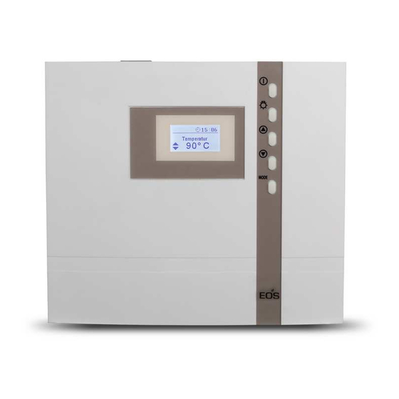
- Page 1 ECON D1 sauna control unit Installation and operating instruction Made in Germany IP x4 Druck Nr. 29344711en/ - 23.15...
-
Page 2: Table Of Contents
English Table of Contents Standard delivery ..........................4 Technical data ............................4 General information concerning sauna bathing ..............5 General safety precautions ......................6 Installation of the control unit .......................8 Wall mount xture ..........................8 Surface-mounted installation ......................8 Recessed installation ........................9 Connecting the sensor cables .......................10 Installation of the heater sensor ....................10 Electrical connection ........................12 Connecting the sauna heater ......................12... - Page 3 Switching o the sauna unit in the Finnish mode ..............21 Switching on the sauna unit with Life - Guard ................22 Individual settings ..........................23 Cabin temperature ..........................23 Auto-Stop .............................24 Life - Guard ............................25 Unit fuses...............................27 Error messages ............................28 The device switch (Switch-o ) ......................29 Service Address: ..........................30 Guarantee .............................30 General Terms and Conditions of Service .................31...
-
Page 4: Standard Delivery
Standard delivery (subject to changes) Sauna control unit includes the following parts: 1. Temperature sensor, consisting of: sensor circuit board with over-temperature fuse, KTY-sen- sor, sensor housing, two mounting screws 3 x 25 mm and sensor cable approx. 2 m long (red and white). -
Page 5: General Information Concerning Sauna Bathing
Dear customer General information You have purchased a high-quality technical Please check whether the unit has arrived in per- device with which you will have years of sauna fect condition. Any transport damages should be fun. This sauna control unit was designed and immediately reported to the freight forwarder inspected according to the current European delivering the goods or you should contact the... -
Page 6: General Safety Precautions
General safety precautions ature setting. The temperature can be held within operating parameters and This device can be used by children aged • a minimal temperature gradient inside 8 upwards and by persons with physical, the bench area of the sauna cabin can be sensory, or mental disabilities, or who achieved only if unit is assembled correct- have inadequate experience and knowl-... - Page 7 When designing the cabin ensure that the external exposed glass surfaces only re- ach a maximum temperature of 76°C. If ne- cessary, protective features need to be tted. Attention! Dear customer, according to the valid regulations, the electrical connection of the sauna heater and the control box has to be carried out through the specialist of an authorized electric shop...
-
Page 8: Installation Of The Control Unit
Fasten the housing bottom at the two bot- Installation of the control unit tom openings (Fig. 4) rmly to the cabin wall. Wall installation The control unit may only be mounted outside the sauna cabin. It is advisable to select the out- ca. -
Page 9: Recessed Installation
Recessed installation 1. Cut out a wall section that is at least 3.5 cm deep according to the dimension in Fig. 5. 21 cm Fig. 5 Insert the supplied rubber grommets into the openings at the rear wall of the housing and insert the connecting cables through these openings. -
Page 10: Connecting The Sensor Cables
2. Drill a hole to lead the cable through, pre- Connecting the sensor cables ferably through the middle of one of the You should not install sensor and power supply wooden boards. lines together, or lead them through the same 3. - Page 11 Hole Sauna ceiling Centre sensor housing on middle section L1 L2 L3 N W V U N Sensor cables Fig. 11 142°C Limiter weiß / white Sensor rot / red Fig. 12 6. After completed installation and correct commissioning of the control unit, the line 12:00 for overtemperature protection must be checked for short-circuits.
-
Page 12: Electrical Connection
Electrical connection Connecting the sauna heater The electrical connection may only be done by a certi ed electrician in compliance with the guidelines of the local utility company Install the sauna heater in front of the air intake and the VDE. according to the manufacturer’s installation in- structions. -
Page 13: Installation Diagram
Installation diagram ECON 400 V 3 N AC 50 Hz Terminal arrangement on the circuit board. Plug for sensor connection L1 L2 L3 N W V U N... -
Page 14: Connecting The Sauna Heater
Connecting the sauna heater 142°C ECON L1 L2 L3 Limiter weiß / white Sensor rot / red max. 100 W P max. 9 kW Warning: Always connect 400 V 3 N AC 50 Hz the neutral conductor (N) of the sau- na oven. -
Page 15: Operation
Operation Once the system has been installed with all components and all covers have been xed, you can put your sauna unit into operation. Over the following pages we will show you the options provided to you with the control. General The user interface MODE... -
Page 16: Default Display Stand-By
Default display Stand-by is shown if the system is in Stand-by mode. 12:00 Reset to this display takes place from other Temperature menu items if no activity is carried out > 15 s. 30° C Default display in operation is shown if the system is in operation. The dis- 12:00 12:00 play switches between the set temperature... -
Page 17: Cabin Lighting
Parameters that are highlighted in black on the display can be adjusted. Temperature 30 °C Parameters that blink on the display can be changed and are shown in these instructions as displayed. In order to adjust the individual values to the 12:00 particular desires, brie y push the Temperature... -
Page 18: Initial Commissioning
Initial commissioning 12:00 12:00 Life - Guard 12:00 12:00 Life - Guard > 3 s MODE 12:00 Time of day > 3 s MODE 0 : 00 0 : 00 12:00 Time of day 12 : 30 12:00 Time of day 12 : 00 MODE 12:00... -
Page 19: Change Language
Change language Change time 12:00 12:00 Temperature Temperatur 30° C 30° C & & MODE MODE 12:00 12:00 Time of day Tageszeit 12 : 30 12 : 30 MODE 12:00 12:00 Time of day 12 : 30 MODE 12:00 12:00 Time of day 15 : 30 MODE... -
Page 20: Activating The Life-Guard
Activating the Life-Guard 12:00 Life - Guard is a settable relatively short time, Time of day e.g. 20 minutes after which the sauna unit is 15 : 45 switched o , except for the cabin lighting. Af- ter this time has elapsed the unit can be MODE switched on again by pushing the - button for 15 s... -
Page 21: Activate/Deactivate The Child Lock
Activate/deactivate the child lock Switching on the sauna unit If the child lock is activated (the key symbol is 12:00 shown in the top area of the display) only the cabin lighting can be switched. All other but- Temperature tons are without function. Activating / deacti- 30°... -
Page 22: Switching On The Sauna Unit With Life-Guard
Switching on the sauna unit with Life-Guard 12:00 Temperature 30° C > 3 s 12:00 12:00 Temperature Auto-stop 30° C 5 : 59 The sauna heater is now heating normally, wit- hout "Life-Guard"-time. To activate the function "Life-Guard". MODE 12:00 Life - Guard 14 min After expiration of the "Life-Guard"... -
Page 23: Individual Settings
Individual settings Hereafter we are showing you options that allow you to adjust the controls to your individual needs. The various parameters can be changed in Stand-by or in operation and the changes are saved in the unit. Changes made in operation are e ective directly. Setting range: Finnish mode 30 - 115°C Cabin temperature In operation... -
Page 24: Auto-Stop
Auto-Stop Auto-Stop is the time to which the heating time is limited. The sauna unit automatically turns o once this time has expired. The time is adjustable from 0:01 to 6:00 hours. In Stand-by In operation 12:00 12:00 12:00 Temperature Auto-stop Temperature 30°... - Page 25 12:00 12:00 Auto stop Auto stop 3:30 3:30 > 3 s > 3 s MODE MODE 12:00 12:00 Auto stop Temperature 3:30 30° C 15 s > 3 s 12:00 12:00 Temperature Temperature 30° C 30° C...
-
Page 26: Life - Guard
Life - Guard Here you can set after what time the sauna unit is switched o and by pushing the - button MODE again you can restart the „Life - Guard“ time. This setting can only be selected in Stand-by when the function „Life - Guard“ is activated. In Stand-by 12:00 12:00... -
Page 27: Unit Fuses
Replace device fuse Only allow a specialist to carry out this work. Before working on the open control unit, disconnect all poles from the mains. (Switch o the master switch, or trigger the FI switch). Risk of an electrical shock! Loosen the four screws on the opened unit that hold the circuit board. -
Page 28: Error Messages
Error messages The control unit continuously monitors the sensor for short circuits and interruptions. The error messages appear as follows: Display Cause Remedy = interrupted room sensor circuit Arrange for a specialist to 12:00 The temperature sensor (PTC) is faul- check the lines and PTC. -
Page 29: The Device Switch (Switch-O )
The device „Switch-o “ switch Switch-o by ECON control units You will nd the rocker switch on the top side of the control unit. You can completely discon- nect the control unit from the mains using this switch. Switch-o Unit turned on (default Position I) Press the switch on the left side of the rocker Unit fully switched o... -
Page 30: Service Address
Outside of Germany please contact your spe- Service Address: cialist dealer in case of warranty claims. Direct warranty processing with our service depart- EOS Saunatechnik GmbH ment is in this case not possible. Schneiderstriesch 1 35759 Driedorf, Germany Equipment commissioning date:... -
Page 31: General Terms And Conditions Of Service
shipments via parcel post. The manufacturer shall accept General Terms and Conditions of Service no liability for damage incurred as a result of improper I. Scope packaging in an individual shipment. Unless otherwise agreed in writing in a speci c case, the- VI.
Need help?
Do you have a question about the ECON D1 and is the answer not in the manual?
Questions and answers