Table of Contents
Advertisement
Quick Links
Advertisement
Table of Contents

Related Manuals for Make Noise Maths


Summary of Contents for Make Noise Maths
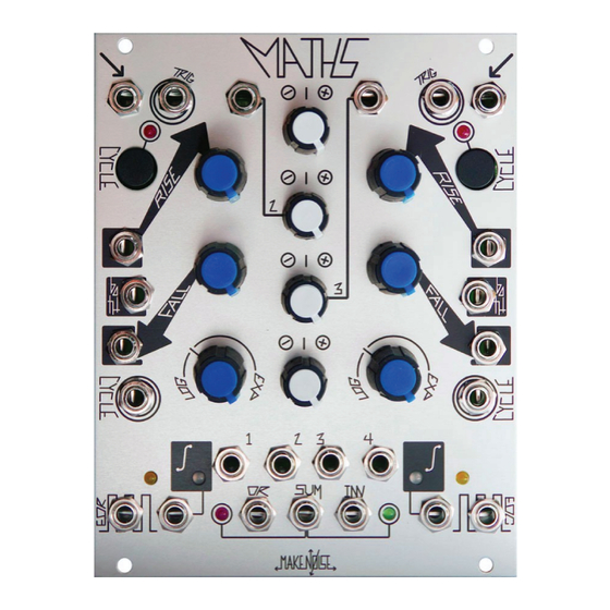
- Page 1 v2.6...
-
Page 2: Table Of Contents
MATHS Limited Warranty ----------------------------------------------------3 Installation ----------------------------------------------------------4 Overview ---------------------------------------------------------5 Channel 1 Panel Controls -----------------------------------------6 Channel 4 Panel Controls --------------------------------------------8 SUM and OR Bus -----------------------------------------------------10 Getting Started -------------------------------------------------------12 Rise, Fall, and Vari-Response -------------------------------------13 Signal Outputs ------------------------------------------------------14 Tips & Tricks ---------------------------------------------------------15 Patch Examples ------------------------------------------------------16... -
Page 3: Limited Warranty
Make Noise to be the fault of the user are not covered by this warranty, and normal service rates will apply. During the warranty period, any defective products will be repaired or replaced, at the option of Make Noise, on a return-to-Make Noise basis with the customer paying the transit cost to Make Noise. -
Page 4: Installation
Eurorack style bus board, minding the polarity so that the RED stripe on the cable is oriented to the NEGATIVE 12 Volt line on both the module and the bus board. On the Make Noise 6U or 3U Busboard, the negative 12 Volt line is indicated by the white stripe. -
Page 5: Overview
Even small voltages are readable on these LEDs. 3. As Make Noise now o ers a Multiple the Signal Output Multiple (from the original MATHS) has been changed to a Unity Signal Output. It allows for creating two variations of output, one at unity and the other as processed through the Attenuverter. -
Page 6: Channel 1 Panel Controls
14 15 MATHS Channel 1 1. Signal Input: Direct Coupled input to circuit. Use for Lag, Portamento, ASR (Attack Sustain Release type envelopes). Also input to Sum/OR Bus. Range +/-10V 2. Trigger Input: Gate or Pulse applied to this input triggers the circuit regardless of activity at the Signal Input. The result being a 0V to 10V function, aka Envelope, whose characteristics are de ned by the Rise, Fall, and Vari-Response parameters. - Page 7 9. Fall CV Input: Linear control signal input for Fall parameter. Positive control signals increase Fall time, Negative control signals decrease Fall Time with respect to the Fall panel control. Range +/-8V 10. Cycle Input: On Gate HIGH, Cycles on. On Gate LOW, MATHS does not Cycle (unless the Cycle button is engaged). Requires minimum +2.5V for HIGH.
-
Page 8: Channel 4 Panel Controls
MATHS Channel 4 1. Signal Input: Direct Coupled input to circuit. Use for Lag, Portamento, ASR (Attack Sustain Release type envelopes). Also input to SUM/OR Bus. Range +/-10V 2. Trigger Input: Gate or Pulse applied to this input triggers the circuit regardless of activity at the Signal Input. The result being a 0V to 10V function, aka Envelope, whose characteristics are de ned by the Rise, Fall, and Vari-Response parameters. - Page 9 9. Fall CV Input: Linear control signal input for Fall parameter. Positive control signals increase Fall time, Negative control signals decrease Fall Time with respect to the Fall panel control. Range +/-8V 10. Cycle Input: On Gate High, circuit Cycles. On Gate Low, MATHS does not Cycle (unless the Cycle button is engaged). Requires minimum +2.5V for High 11.
-
Page 10: Sum And Or Bus
SUM and OR Bus 1. Direct Coupled Channel 2 Signal Input to Attenuverter and Sum/OR Bus. Normalized to a +10V reference for generation of voltage o sets. Input Range +/-10Vpp. 2. Direct Coupled Channel 3 Signal Input to Attenuverter and Sum/OR Bus. Normalized to a +5V reference for generation of voltage o sets. - Page 11 SUM and OR Bus (cont’d) 7. CH. 1 Variable Output: The applied signal as processed by CH. 1 controls. Normalized to the SUM and OR busses. Inserting a patch cable removes the signal from the SUM and OR busses. Output Range +/-10V 8.
-
Page 12: Getting Started
NOT re-trigger on the rising portion of the function. This allows clock and gate division since MATHS could be programmed to ignore incoming clocks and gates by setting the Rise Time to be greater than the time between the incoming Clocks and/ or Gates. -
Page 13: Rise, Fall, And Vari-Response
Signal Input and Trigger Input. The range of times is larger than the typical Envelope or LFO. MATHS creates functions as slow as 25 minutes (Rise and Fall full CW and external control signals added to go into "slow-ver-drive") and as fast as 1khz (audio rate). -
Page 14: Signal Outputs
Signal Outputs There are many di erent signal outputs on the MATHS. All of them are situated at the bottom of the module. Many of them have LEDs situated nearby for visual indication of the signals. The Variable Outs These outputs are labeled 1, 2, 3 and 4 and are associated with the four Attenuverter controls in the center of the module. These outputs are all determined by the settings of their associated controls, esp. -
Page 15: Tips & Tricks
-Use the INV SUM Output where you require reversed modulation but do not have means for inversion at the CV destination (Mix CV Input on ECHOPHON, for example). -Feeding an inverted signal from MATHS back into the MATHS at any of the CV inputs is highly useful for creating responses that are not covered by the Vari-Response control alone. -
Page 16: Patch Examples
Patch Ideas: Analog Signal Processing, Voltage MATHS! Typical Voltage Controlled Triangle Function (Triangle LFO) Set CH. 1 (or 4) to Cycle. Set Rise and Fall Panel Control to 12:00, Vari-Respnose to Linear. Set CH. 2 Attenuverter to 12:00. Patch SUM Output to Both Control Input. - Page 17 Patch Ideas: Analog Signal Processing, Voltage MATHS! Voltage Controlled Sustained Function Generator (A/S/R EG) A gate applied to the Signal Input of CH. 1 or 4 starts the function which Rises from 0V to the level of the applied Gate, at a rate...
- Page 18 Patch Ideas: Analog Signal Processing, Voltage MATHS! Half Wave Recti cation Apply bi-polar signal to CH. 1, 2, 3, or 4 Inputs. Take output from OR Output. Mind the normalizations to the OR buss. Typical Voltage Controlled Pulse/ Clock w/ Voltage Controlled Run/...
- Page 19 MATHS CH. 4 Both Input. Patch CH. 4 Variable Output to CH. 1 BOTH CV Input. Unity Signal Output to modulation destination. MMG Freq and Signal Input controls and MATHS CH. 1 and 4 Attenuverters are of great interest in addition to the Rise and Fall parameters.
- Page 20 Patch Ideas: Analog Signal Processing, Voltage MATHS! Envelope Follower Apply signal to be followed to Signal Input CH. 1 or 4. Set Rise to 12:00. Set and or modulate Fall Time to achieve di erent responses. Take output from associated Channel Signal Output for positive and negative Peak Detection. Take output from OR buss Output to achieve more typical Positive Envelope Follower function.
Need help?
Do you have a question about the Maths and is the answer not in the manual?
Questions and answers