
Related Manuals for Trocen AWC708C Plus


Summary of Contents for Trocen AWC708C Plus
- Page 1 AWC708C PLUS Motion Control User Manual Laser Motion Control RV 1.0 2017.06 www.sztrocen.com Copyright © 2016 Trocen Automation Tech. Co. Ltd. All Rights Reserved...
- Page 2 Trocen) reserves the right to modify the products and product specifications in this manual without prior notice. Trocen is not liable for any loss or liability arising directly, indirectly, specifically, incidental or consequential due to the use of this manual or this product.
- Page 3 AWC708C PLUS Motion Control User Manual Contact Us Shenzhen Trocen Automation Tech. Co. Ltd. First Floor, Building 4, Zhiheng Industrial Park, Nantou Pass Second Road, Nanshan District, Shenzhen City, Guangdong Province, China Tel: +86-0755-27958262 Fax: +86-0755-27447913-608 Email: qiancheng@sztrocen.com Website: www.sztrocen.com...
- Page 4 First Floor, Building 4, Zhiheng Industrial Park, Nantou Pass Second Road, Nanshan District, Shenzhen City, Guangdong Province, China Code: 518100 User Manual By reading this instruction, the users will know the basic composition, installation and how to use AWC708C PLUS. WWW.SZTROCEN.COM...
- Page 5 For Who This manual is applicable to engineers who have a certain understanding of laser mechanical automation and electrical circuits. Main Content The composition, installation and use of AWC708C PLUS are introduced in detail Relevant Document 《LaserCAD User Manual》 WWW.SZTROCEN.COM...
-
Page 6: Table Of Contents
AWC708C PLUS Motion Control User Manual Content 1. Product Introduction ................8 1.1 System Introduction ..............8 1.2 Terms and Explanation ............... 9 1.3 Unpack ..................9 1.4 Panel Preview ................11 1.5 Buttons ..................12 1.5.1 Function Keys ..............12 1.5.2 Direction Keys .............. - Page 7 AWC708C PLUS Motion Control User Manual 5.1 File ................... 45 5.1.1 Document Params Settings ..........45 5.1.2 Layer Params Settings ............ 47 5.2 Count..................49 5.3 Working Property ..............51 6. System Menu ..................53 6.1 U Disk Files ................53 6.1.1 Work Files ..............
- Page 8 AWC708C PLUS Motion Control User Manual 6.9 Language .................. 84 6.10 System Version ............... 84 7. Manufacture Params Settings ............87 7.1 Axis Parameters ................ 87 7.2 Laser Parameters ..............90 7.3 I/O Parameters ................. 92 7.4 Auto Reset Settings ..............93 7.5 HardLimit Settings ..............
-
Page 9: Product Introduction
AWC708C PLUS Motion Control User Manual 1. Product Introduction 1.1 System Introduction AWC708C PLUS is a universal motion controller for laser cutting, laser engraving and other fields developed by Shenzhen Trocen Automation Tech co., LTD. This controller featured with single/double-head/three-... -
Page 10: Terms And Explanation
AWC708C PLUS Motion Control User Manual ⚫ Optical coupler, anti-electromagnetic interface and system stability. ⚫ Faster reading files under USB, U Disk and network. ⚫ Support single-head/double-head and multi-head control (the most is 4 heads) and power controlling stand-alone. 1.2 Terms and Explanation... - Page 11 AWC708C PLUS Motion Control User Manual the after-sales service of Trocen company. Table1-3-1 Wire Introduction Name Appearance Introduction Panel and The panel (mainboard) of AWC708C PLUS. mainboard Wiring Board The wiring board of AWC708C PLUS. USB Cable (3m) Connect computer and panel by USB.
-
Page 12: Panel Preview
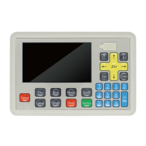
AWC708C PLUS Motion Control User Manual Screw (2) Used to fasten the mainboard. 1.4 Panel Preview There are LCD display, soft keys and U disk slot on panel. Figure1-4-1 Panel Preview WWW.SZTROCEN.COM... -
Page 13: Buttons
AWC708C PLUS Motion Control User Manual Figure1-4-2 Size of Main Board 1.5 Buttons According to the different use of keys, all keys are roughly divided into three categories: function keys, number keys and direction keys. 1.5.1 Function Keys Function key is designed to directly realize a specific operation function. - Page 14 AWC708C PLUS Motion Control User Manual Frames the working area from the origin point of the current file. Menu Show the main menu. Shift Combine function key. Test usage. Press the key, the laser tube will give Laser out light. It’s used to adjust optical path.
- Page 15 AWC708C PLUS Motion Control User Manual On the main page, press【File】and you could see the memory files stored in the mainboard. Figure1-5-1 File Interface Move cursor to the file you need, press【Enter】, you could set the file parameters. Figure1-5-2 File Parameters Setting Page...
-
Page 16: Direction Keys
AWC708C PLUS Motion Control User Manual ⚫ Move cursor to【Select】, press【Enter】and set current file as work file. ⚫ Move cursor to【Data Check】, press【Enter】. If the graphics is the same as that in PC, the system will prompt “File Data OK!”, then the graphics will be allowed to process. - Page 17 AWC708C PLUS Motion Control User Manual ⚫ 【Z↑】 【Z↓】 Move cursor when the direction keys 【↑】 【↓】 【←】 【→】 are occupied, and these two keys are used to move Z axis directly. ⚫ 【Z/U】 Z axis with auto focus. Enter the Z/U Control page, press 【Z↑】 【Z↓】...
-
Page 18: Number Keys
AWC708C PLUS Motion Control User Manual 1.5.3 Number Keys Used to modify parameter values. 【0】and【C】keys also can be used to move feeding axis (U axis). 1.6 Wiring Board The panel and other parts of machine are connected by wiring board. The components as below: ⚫... -
Page 19: Wiring Board Appearance
AWC708C PLUS Motion Control User Manual 1.6.1 Wiring Board Appearance Figure1-6-1 Wiring Board Appearance WWW.SZTROCEN.COM... -
Page 20: Port Instruction
AWC708C PLUS Motion Control User Manual Figure1-6-2 Wiring Board Ports Introduce 1.6.2 Port Instruction 1.6.2.1 Power Supply Port The power supply ports provide power to wiring board and panel. Please pay more attention to polarity when connect them. Don’t make the polarity reverse. - Page 21 AWC708C PLUS Motion Control User Manual 1.6.2.2 Port of Panel and Wiring Board Connect panel and wiring board with CN1 and CN2 cables. Table1-6-2 Port of Panel and Wiring Board Name Introduction Connect CN1 port of panel and wiring board with CN1 cable.
- Page 22 AWC708C PLUS Motion Control User Manual DC24V Output DC voltage (24V) Reserved 12.IN Reserved Power ground Wiring diagram of signal input: Figure1-6-3 Wiring Diagram for Signal Input 1.6.2.4 Signal Output There are two groups of output ports to supply power and control signals.
- Page 23 AWC708C PLUS Motion Control User Manual Parameter interface, with the minimum value of 0.01. Table1-6-4 Output Port Instruction Name Instruction Blowing signal (blow all the working time): OUT1 OUT1 Blowing when output is high logic level. OUT1 Do not blow when output is low logic level.
- Page 24 AWC708C PLUS Motion Control User Manual Output signals control laser blowing generally. The wiring diagram is shown below (blow all the working time). Figure1-6-4 Blowing Control Diagram 1.6.2.5 Laser Power Supply Port The wiring board provides 4 groups of laser output control ports.
- Page 25 AWC708C PLUS Motion Control User Manual Digital signal. The output voltage is 0~5V, and it will change according to the power. Laser switch signal. Power ground. DC5V Output DC voltage (5V). Water Protection. Digital signal. The output voltage is 0~5V, and it 4.Laser3...
- Page 26 AWC708C PLUS Motion Control User Manual will change according to the power. Laser switch signal. Power ground. Different lasers have different connection modes. Take ordinary glass tube laser as example. The optical signal of ordinary glass tube laser is 5V, and set low level for light emitting.
- Page 27 AWC708C PLUS Motion Control User Manual Figure1-6-5 Ordinary Glass Tube Laser Diagram AWC708C PLUS Ordinary Glass Tube Laser 信号名 引脚 5.LASER2 DC5V Figure1-6-6 Pins of Laser Power Source Power Ground Laser Energy Control Signal (5V) Output DC Voltage (5V) G IN 5V...
- Page 28 AWC708C PLUS Motion Control User Manual and if the laser light control signal is high level, connect the H pin of laser power. 1.6.2.6 Motor Drive Control Port The wiring board can provide up to 6 motor driver connections, and users can choose step driver or servo driver according to the need.
- Page 29 AWC708C PLUS Motion Control User Manual Direction signal DC5V Output DC voltage (5V) Pulse signal Direction signal DC5V Output DC voltage (5V) Pulse signal Direction signal DC5V Output DC voltage (5V) Pulse signal Direction signal WWW.SZTROCEN.COM...
- Page 30 AWC708C PLUS Motion Control User Manual The diagram below shows the connection of step driver. Figure1-6-7 Diagram of Driver Connection 1.6.2.7 Limit Signal The wiring board provides 6-way sensor limit signal access. Each axis supports maximum and minimum coordinate limit signal input. This system supports working range limitation, so users do not need to install hard limit sensor, just set the【Range】parameter on the Axis Parameters...
- Page 31 AWC708C PLUS Motion Control User Manual Table1-6-7 X/Y Limit Signal Input Name Instruction DC24V Output DC voltage (24V). The hard limit of Y axis. The input signal of hard ELY+ limit sensor, when Y axis moves to the maximum coordinate position.
- Page 32 AWC708C PLUS Motion Control User Manual The hard limit of U axis. The input signal of hard ELU+ limit sensor, when U axis moves to the maximum coordinate position. The hard limit of Z axis. The input signal of hard...
- Page 33 AWC708C PLUS Motion Control User Manual Table1-6-9 V/W Limit Signal Input Name Instruction DC24V Output DC voltage (24V). The hard limit of W axis. The input signal of hard ELW+ limit sensor, when W axis moves to the maximum coordinate position.
- Page 34 AWC708C PLUS Motion Control User Manual Figure1-6-8 Diagram of Limit Signal WWW.SZTROCEN.COM...
-
Page 35: Lasercad Installation
AWC708C PLUS Motion Control User Manual 2. LaserCAD Installation You can go through 《LaserCAD User Manual》 for more details about installation and how-to-use LaserCAD. WWW.SZTROCEN.COM... -
Page 36: Simplified Installation
AWC708C PLUS Motion Control User Manual 3. Simplified Installation The content of this chapter is mainly about the hardware initial installation of the product and the setting of basic software parameters. Please refer to the following chapters for the detail settings and descriptions of other parameters. -
Page 37: Input Test
AWC708C PLUS Motion Control User Manual ⚫ Figure 3-1-1 shows the diagram of ordinary glass tube laser. ⚫ Connect the blow control ports to corresponding electromagnetic valves to control blow. ⚫ Connect the axis limit ports to corresponding axis limiters. -
Page 38: Set The Origin Point Of Machine
AWC708C PLUS Motion Control User Manual whether the signals changes, so as to confirm whether the wiring is accurate and effective. 3.3 Set the Origin Point of Machine Connect machine and wiring board as Figure3-1-1. Power on and observe the motion of axis. If the axis moves random, please press 【Stop】 at once. -
Page 39: Key Direction
AWC708C PLUS Motion Control User Manual start, please make sure to enable the axis auto reset function. Detail settings refer to Chapter 7.4. 3.4 Key Direction On the main page, press【↑】 【↓】 【←】 【→】to move motion axis, and check whether the motion direction is the same as key direction. If not, please modify the【Key Direction】on the axis parameters page. - Page 40 AWC708C PLUS Motion Control User Manual 4) Measure the distance between A and B, then input the value into 【Actual Length】. 5) On the main page, press 【Stop】 + 【Shift】 at the same time to open the Manufacture Params Settings page. Then move cursor to 【 Axis Parameters】option and press【Enter】.
- Page 41 AWC708C PLUS Motion Control User Manual 3) On the Jog Control page, move cursor to【Z Jog】, then press direction key (【←】/【→】) one time to make the laser heads move a jog distance on the X direction. Then press【Laser】and mark the laser head2 position with B.
-
Page 42: Hard Limit And Range
Manufacture Params Settings page. Then move cursor to【HardLimit Settings】and press【Enter】, users can enable or disable the hard limit parameters. AWC708C PLUS supports range function, so users do not need to install hard limit sensors, just setting【Range】parameters on the relevant axis parameters page will be enough. -
Page 43: Main Interface Preview
AWC708C PLUS Motion Control User Manual 4. Main Interface Preview Figure4-1 Main Interface Speed/Power/Time/Status: Work: Working parameters; Idle: Laser power. Table4-1 Main Interface Introduce Name Instruction Top Bar Display the type of control card, local date and time. File Display the file name currently being processed. - Page 44 AWC708C PLUS Motion Control User Manual Displays the Max & Min power of laser 1 and 2. Max power means working power. Min power means turning power. During cutting process, if the cutting lines is uneven (different cutting Max Power1...
- Page 45 AWC708C PLUS Motion Control User Manual process of the current file under working state. Displays the X & Y coordinate in the working state. WWW.SZTROCEN.COM...
-
Page 46: Main Page Function Introduction
AWC708C PLUS Motion Control User Manual 5. Main Page Function Introduction 5.1 File 5.1.1 Document Params Settings On the main page, press【Enter】to make the file name highlighted as shown below. Then press【Enter】to open Document Params Settings interface. Figure5-1-1 Select File Name... - Page 47 AWC708C PLUS Motion Control User Manual Figure5-1-2 Document Params Settings Move the cursor to【Document Property Settings】, press【Enter】. Press 【↑】 【↓】 【←】 【→】to move cursor, press number keys to modify parameters, and press【Enter】to save settings. Figure5-1-3 Set Document Property WWW.SZTROCEN.COM...
-
Page 48: Layer Params Settings
AWC708C PLUS Motion Control User Manual Table5-1-1 Set Document Property Instruction Name Instruction Repeat Count Machine repeat working times. The interval between the initial file being finished and the next Repeat Delay (s) one of the same. Feed Distance Distance of each movement of the feeding axis. - Page 49 AWC708C PLUS Motion Control User Manual During cutting current layer, if the cutting lines are uneven (different cutting depth), the maximum and minimum power of the laser head shall be adjusted to ensure the best cutting effect. If the maximum and minimum power is set too high, the cutting material may be damaged.
-
Page 50: Count
AWC708C PLUS Motion Control User Manual Max Power1 (%) The max power of laser head1 (working power). Min Power1 (%) The min power of laser head1 (turning power). Max Power2 (%) The max power of laser head2 (working power). Min Power2 (%) The min power of laser head2 (turning power). - Page 51 AWC708C PLUS Motion Control User Manual Figure5-2-1 Clear Total Count Figure5-2-2 Clear Total Count WWW.SZTROCEN.COM...
-
Page 52: Working Property
AWC708C PLUS Motion Control User Manual 5.3 Working Property On the main page, press 【Enter】 to make the cursor highlighted and move cursor to【Speed】. Press【Enter】to open Set Laser Power While Idle page. Figure5-3-1 Select Speed Option WWW.SZTROCEN.COM... - Page 53 AWC708C PLUS Motion Control User Manual Press【↑】 【↓】 【←】 【→】to move cursor, press number keys to modify parameters, and press【Enter】to save settings. Fiugre5-3-2 Idle Laser Power Setting Page Table5-2-1 Idle Laser Power Instruction Name Instruction Key Move Speed The speed of axis when press direction keys on panel.
-
Page 54: System Menu
AWC708C PLUS Motion Control User Manual 6. System Menu 6.1 U Disk Files Insert a U disk into the U disk slot on the panel. If your U disk has a "light indicator" (shows connectivity) and shows that it's connected, press 【Menu】to enter the main menu, move the cursor to【U Disk Files】... - Page 55 AWC708C PLUS Motion Control User Manual Figure6-1-2 U Disk Files ○ The U disk must be formatted to FAT32 File system in advance. Quick Format is forbidden. Any other files formations are not supported. ○ Recommend using a U disk with a "light indicator" to ensure if the U disk is connected successfully with the main board ○...
-
Page 56: Work Files
AWC708C PLUS Motion Control User Manual If the U disk can’t be read, you will see the interface below. Figure6-1-3 No U Disk Interface 6.1.1 Work Files Move the cursor to【Work Files】and press【Enter】. On the panel, the working file in the U disk will be presented. The right side shows the working file previewing. -
Page 57: Config Files
AWC708C PLUS Motion Control User Manual Figure6-1-4 U Disk Work Files List The working file in the U disk is saved with a suffix of UD5. Files other than the “.UD5” file extension will not readable. 6.1.2 Config Files Move cursor to【Config File】and press【Enter】. Move cursor to the file which you need to copy to main board. -
Page 58: Upgrade Files
AWC708C PLUS Motion Control User Manual Figure6-1-5 Config Files List 6.1.3 Upgrade Files Move cursor to【Upgrade Files】and press【Enter】. Move the cursor to the file you need, press【Enter】then it will start the upgrading process. Figure6-1-6 Upgrade Files WWW.SZTROCEN.COM... -
Page 59: Save Current Config To U Disk
AWC708C PLUS Motion Control User Manual Don’t turn off the power during upgrade, otherwise it will cause damage to the mainboard. The upgrade will take about 30s. After finishing upgrade, the mainboard will reset automatically. 6.1.4 Save Current Config to U Disk Move cursor to【Save Current Config to U Disk】and press【Enter】to save... - Page 60 AWC708C PLUS Motion Control User Manual Figure6-2-1 Origin Manage Interface Move cursor to【Origin1 Manage】, press【Enter】to enter the Origin1 Manage interface. Move cursor to【Set current position as the origin】, press【Enter】to set the current position of laser head as origin point. Other origin points will be set like this.
-
Page 61: Jog Control
AWC708C PLUS Motion Control User Manual Take 【Origin1 Manage】as an example. Figure6-2-2 Origin Mange Instruction 6.3 Jog Control On the main page, press 【Menu】 , move cursor to 【Jog Control】 and press 【Enter】to enter Jog Control page. Then press【Z↑】 【Z↓】to modify the distance. -
Page 62: Cut Box
AWC708C PLUS Motion Control User Manual Fiugre6-3-1 Jog Control Interface 6.4 Cut Box On the main page, press【Menu】and move cursor to【Cut Box】, press 【Enter】to enter the Cut Box page. Move cursor to【Blank Distance】, and press number keys to modify parameters, then move cursor to【Start cutting box】and press【Enter】to start cut box function. -
Page 63: Axes Control
AWC708C PLUS Motion Control User Manual Fiugre6-4-1 Cut Box Interface Table6-4-1 Cut Box Instruction Name Instruction Blank Distance The distance between the border of graphics s and the border (mm) of cutting. 6.5 Axes Control On the main page, press【Menu】and move cursor to【Axes Control】, press 【... -
Page 64: Motion Parameters Settings
AWC708C PLUS Motion Control User Manual limiter position. Fiugre6-5-1 Axes Control Interface 6.6 Motion Parameters Settings On the main page, press 【Menu】 and move cursor to 【Motion Parameters Settings】 , press 【Enter】 to enter Motion Parameters Settings page. Press 【↑】 【↓】to move cursor and press number keys to modify parameters, press【Enter】to save settings. - Page 65 AWC708C PLUS Motion Control User Manual Fiugre6-6-1 Motion Parameters Settings Interface The settings of these parameter items will affect the cutting effect, please adjust according to your requirements. Table6-6-1 Motion Parameters Instruction Name Instruction Space Speed The movement speed of laser head when there is (mm/s) no laser output.
- Page 66 AWC708C PLUS Motion Control User Manual (mm/s2) this value increases or decreases in unit of 50 or 100 each time. Engrave Acc The variation of engraving speed and it is only (mm/s2) effective to engrave. Start Speed The initial speed of laser head from rest to motion.
- Page 67 AWC708C PLUS Motion Control User Manual The start speed is the initial speed of the laser head from rest to start movement. If the cutting line is too thick at the initial position of cutting, it indicates that the parameter value is too small. If the line jitters at the initial position of cutting, this parameter value is set too large.
-
Page 68: Common Parameters Settings
AWC708C PLUS Motion Control User Manual 6.7 Common Parameters Settings On the main page, press 【 Menu 】 and move cursor to 【 Common Parameters Settings】, press【Enter】. Fiugre6-7 Common Parameters Settings Interface 6.7.1 Work Mode On the Common Params Settings page, move cursor to【Work Mode】... - Page 69 AWC708C PLUS Motion Control User Manual Fiugre6-7-1 Common Parameters Settings Interface Table6-7-1 Work Mode Instruction Name Instruction Enable: the laser head will be back to Origin after resetting. Go Origin After Disable: the laser head will stay at the machine origin point Reset (zero point) after reset.
- Page 70 AWC708C PLUS Motion Control User Manual point. Current Position: laser head will stay at where task finished. Current Origin: go back to Origin point after finishing work. Go Back Position Zero Coord: laser head goes back to machine zero point since all finished.
- Page 71 AWC708C PLUS Motion Control User Manual Users can enable or disable the Auto Origin (Beyond border limit) function as required. Disable the function, if the graphics beyond the working range, the system prompts "Beyond border limit! Continue?", press【Enter】key to continue to cut, part of the graphics beyond border limit will not be cut, as shown in Figure 6-7-3.
- Page 72 AWC708C PLUS Motion Control User Manual Fiugre6-7-3 Part of the Cutting (Panel) Fiugre6-7-4 Part of the Cutting (LaserCAD) WWW.SZTROCEN.COM...
- Page 73 AWC708C PLUS Motion Control User Manual Enable the function, if the graphics beyond the working range, the laser head will automatically adjust position to cut the graphics perfectly. After adjustment, if the graphics still beyond the border, the system prompts "Beyond border limit! Continue?", press【Enter】key to continue to cut,...
-
Page 74: Common Parameters
AWC708C PLUS Motion Control User Manual Fiugre6-7-5 Auto Origin 6.7.2 Common Parameters On the Common Params Settings page, move cursor to 【 Common Parameters】and press【Enter】. Press【↑】 【↓】to move cursor and press number keys to modify parameters, press【Enter】to save settings. The 【 Z AutoFocus】 function is mainly used to control the distance between the laser head and the work table. - Page 75 AWC708C PLUS Motion Control User Manual Config】 ) and set 【 AutoFocus Distance】 here to keep the distance between laser head and working table. Fiugre6-7-6 Common Parameters Interface Table6-7-2 Common Parameters Instruction Name Instruction Auto Focus Distance The distance between the laser head and working (mm) platform.
-
Page 76: Axis Speed Parameters
AWC708C PLUS Motion Control User Manual (mm/s) frame of graphics. The period between laser head optical output and air Blow Open Delay(s) blowing started. The period between laser head optical output stopped and Blow Close Delay(s) air blowing stopped. 6.7.3 Axis Speed Parameters On the Common Params Settings page, move cursor to 【Axis Speed... - Page 77 AWC708C PLUS Motion Control User Manual Table6-7-3 Axis Speed Parameters Instruction Name Instruction Z Work Speed The work speed of Z axis. (mm/s) U Work Speed The work speed of U axis. (mm/s) V Work Speed The work speed of V axis.
-
Page 78: Rotate Engraving & Cutting
AWC708C PLUS Motion Control User Manual 6.7.4 Rotate Engraving & Cutting On the Common Params Settings page, move cursor to【Rotate Engraving & Cutting】and press【Enter】. Press【↑】 【↓】to move cursor, press 【 ← 】 【 → 】 to modify options and press number keys to modify parameters, press【Enter】to save settings. - Page 79 AWC708C PLUS Motion Control User Manual Current Diameter The diameter of the material being processed. (mm) After enable the【Rotary】function, reset the machine, the panel prompts “Rotary is Enabled!”. If the current machine does not support the rotate engraving function, the distance per pulse of rotary axis will change, and the machine cannot cut the graphics normally.
- Page 80 AWC708C PLUS Motion Control User Manual Pulse Count per Rotate = Pulse Number of Motor * (Number of Gears in Gear1 / Number of Gears in Gear2) Figure6-7-10 Fixture Rotate Engraving Users should adjust distance per pulse of rotary axis for roller type rotate engraving &...
- Page 81 AWC708C PLUS Motion Control User Manual per Pulse】, press【Enter】key to enter the To Calculate the Pulse Distance interface, fill A into the【Expected Length】option, fill B into the【Actual Length】option, and click【Enter】key to calculate the distance per pulse of X axis (rotary axis).
-
Page 82: Ccd Config
AWC708C PLUS Motion Control User Manual 6.7.5 CCD Config On the Common Params Settings page, move cursor to【CCD Config】and press【Enter】. Press【↑】 【↓】to move cursor, press【←】 【→】to modify options and press【Enter】to save settings. Figure6-7-12 CCD Config Table6-7-5 CCD Config Instruction Name... -
Page 83: Network Settings
AWC708C PLUS Motion Control User Manual 6.8 Network Settings On the main page, press【Menu】, move cursor to【Network Settings】 and press【Enter】. Press【↑】 【↓】to move cursor, press number keys to modify parameters and press【Enter】to save settings. Figure6-8-1 Network Settings The default IP address of mainboard is 192.168.8.8. When connecting the... - Page 84 AWC708C PLUS Motion Control User Manual TCP/IPv4 option to open the IP address modification interface. Finally, input the corresponding IP address, click OK button to save, other parameters do not need to fill in. Fiugre6-8-2 Modify IP Address WWW.SZTROCEN.COM...
-
Page 85: Language
On the main page, press 【Menu】 and move cursor to 【Language】 , press 【Enter】. Press【←】 【→】to change language and press【Enter】to save settings. AWC708C PLUS now supports nine kinds of languages, Simplified Chinese, Traditional Chinese, English, Portuguese, Turkish, Russian, French, Korea and Arabic. - Page 86 AWC708C PLUS Motion Control User Manual Fiugre6-10-1 System Version Interface Move cursor to 【User authorization code】 and press 【Enter】 . Press 【 ↑】 【↓】to move cursor, press number keys to modify parameters and press 【Enter】to save settings. The user authorization code is used for encryption or decryption. If you don’t need encryption, there is no need to modify it.
- Page 87 AWC708C PLUS Motion Control User Manual Fiugre6-10-2 User Authorization Code Interface WWW.SZTROCEN.COM...
-
Page 88: Manufacture Params Settings
AWC708C PLUS Motion Control User Manual 7. Manufacture Params Settings On the main page, press 【 Stop 】 + 【 Shift 】 together, you will see Manufacture Params Settings page. Figure7-1 Manufacture Params Interface 7.1 Axis Parameters Move cursor to【Axis Parameters】and press【Enter】. Take the X axis parameter setting as an example, other axis parameter settings are the same. - Page 89 AWC708C PLUS Motion Control User Manual Figure7-1-1 Axis Parameters Interface On the X Axis Parameters page, press【↑】 【↓】to move cursor, press 【←】 【→】to modify options, press number keys to modify parameters and press【Enter】to save settings. Figure7-1-2 X Axis Parameters Interface Move cursor to【Distance Per Pulse】, press【Enter】to enter the To...
- Page 90 AWC708C PLUS Motion Control User Manual Calculate the Pulse Distance page. Press【↑】 【↓】to move cursor, press number keys to modify parameters, and press【Enter】to calculate the distance per pulse. The calculation of distance per pulse, please refer to the Chapter 3.5 for more details.
-
Page 91: Laser Parameters
AWC708C PLUS Motion Control User Manual the panel. When set incorrectly, the axis moves opposite direction. The control level that limit switch passes to the control panel. When set incorrectly, the limit will fail. Limit Polarity If the limit sensor is NPN, the limit polarity is negative. - Page 92 AWC708C PLUS Motion Control User Manual 【←】 【→】to modify options, press number keys to modify parameters and press【Enter】to save settings. Figure7-2-1 Laser Parameters Interface Table7-2-1 Laser Parameters Instruction Name Instruction Laser Mode Laser tube type: CO2 Glass Tube, RF tube.
-
Page 93: I/O Parameters
AWC708C PLUS Motion Control User Manual Water protection switch. If enable this function, the machine Laser1 Water Protect will stop working when the machine detects the signal of water stopping. Water protection switch. If enable this function, the machine Laser2 Water Protect will stop working when the machine detects the signal of water stopping. -
Page 94: Auto Reset Settings
AWC708C PLUS Motion Control User Manual Figure7-3-1 I/O Parameters Interface Table7-3-1 I/O Parameters Instruction Name Instruction Foot Switch Enable or disable the foot switch function. Open Protection Enable or disable the open protection function. Feed Switch Enable or disable the feed function. - Page 95 AWC708C PLUS Motion Control User Manual In general, we suggest users to enable axis AutoReset function, and disable the feed axis AutoReset. Figure7-4-1 Auto Reset Setting Interface Table7-4-1 Auto Reset Settings Instruction Name Instruction If enable this function, when power on or reset the machine, XY Auto Reset the XY axis will reset to origin point.
-
Page 96: Hardlimit Settings
Settings】 and press 【 Enter】 . Press 【 ↑】 【↓】 to move cursor, press 【←】 【→】to modify options and press【Enter】to save settings. AWC708C PLUS supports working range limit, users do not need to install hard limiter in general, just set the【Range】on the axis parameters page. -
Page 97: Multihead Settings
AWC708C PLUS Motion Control User Manual Table7-5-1 Auto Reset Settings Instruction Name Instruction X HardLimit HardLimit switch of X axis. If use HardLimit, enable the function here. Y HardLimit HardLimit switch of Y axis. If use HardLimit, enable the function here. - Page 98 AWC708C PLUS Motion Control User Manual Figure7-6-1 MultiHead Interface Table7-6-1MultiHead Instruction Name Instruction Head Count Set the head count, “1” or “2” or “3” or “4” for AWC708C PLUS. TwoHead Type Single belt or double belt. Nearer Laser for Enable or disable the function. LeftOver ZX Head Space The distance between Z and X axis.
- Page 99 WZ Head Space The distance between W and Z axis. (mm) AWC708C PLUS supports MultiHead function, when single laser head works, fill “1” into【Head Count】, when two or more laser heads work, fill “2” / “3” / “4” into the【Head Count】.
- Page 100 AWC708C PLUS Motion Control User Manual Figure7-6-2 Common Cutting Figure7-6-3 Mutual Movable Double Laser Head Cutting WWW.SZTROCEN.COM...
- Page 101 AWC708C PLUS Motion Control User Manual When multi -head cutting, users should do some settings (take two-head cutting as example): 1. Enable【Z AutoReset】function, and set【Head Count】to “2”. 2. Reset the machine, make Laser head1 and Laser head2 laser by press 【Laser】on the panel, and mark these two points, then measure the...
- Page 102 AWC708C PLUS Motion Control User Manual Figure7-6-4 The Odd Number of Graphics Figure7-6-5 The Even Number of Graphics WWW.SZTROCEN.COM...
-
Page 103: Function Config
AWC708C PLUS Motion Control User Manual 7.7 Function Config On the Manufacture Params Settings page, move cursor to【Function Config】and press【Enter】. Press【←】 【→】to modify options and press 【Enter】to save settings. Figure7-7-1 Function Config Interface Table7-7-1 Function Config Instruction Name Instruction The switch of Z-axis Autofocus. If you need Z AutoFocus function, you need to enable this option. - Page 104 AWC708C PLUS Motion Control User Manual Feed While GoOrigin Enable or disable the function. Y-Axis Work For Enable or disable the function. Roller Y&U Axis For Enable or disable the function. Feeding Y&U Axis Feeding Set the direction of Y&U axis feeding.
-
Page 105: Fqa
AWC708C PLUS Motion Control User Manual 8. FQA 1. The top bar displays local date and time. The date and time can be modified, which requires the cooperation of encryption software. If the time changes to 0.0.0, it means the battery in the panel has run out of power and can’t set password for control card. -
Page 106: Appendix 1: Wiring Diagram Of Servo Driver
AWC708C PLUS Motion Control User Manual Appendix 1: Wiring Diagram of Servo Driver Panasonic A5 High Speed Pulse Wiring Diagram Figure 1-1 Panasonic A5 High Speed Pulse Wiring Diagram AWC708C PLUS Servo Panasonic MINAS-A 50P Control Interface Interface Signal Signal... - Page 107 AWC708C PLUS Motion Control User Manual Figure 1-2 Panasonic A5 Low Speed Pulse Wiring Diagram AWC708C PLUS Servo Panasonic MINAS-A 50P Control Interface Interface Signal Signal PULSH1 PULSH2 DC 5V SIGN1 SIGN2 Table1-1 Panasonic A5 Series Basic Setting Parameters Mode...
- Page 108 AWC708C PLUS Motion Control User Manual 2. Yaskawa Wiring Diagram Figure 2-1 Yaskawa Wiring Diagram AWC708C PLUS Servo Yaskawa Σ Series 50P Control Interface Interface Signal Signal PULSH *PULSH DC 5V SIGN *SIGN Table2-1 Yaskawa Σ Series Basic Setting Parameters...
- Page 109 AWC708C PLUS Motion Control User Manual Pn50A 8100 Positive rolling side can be driven. Pn50B 6548 Negative rolling side can be driven. 3. Delta A Series High Speed Pulse Wiring Diagram Figure 3-1 Delta A Series High Speed Pulse Wiring Diagram...
- Page 110 AWC708C PLUS Motion Control User Manual Figure 3-2 Delta A Series Low Speed Pulse Wiring Diagram AWC708C PLUS Servo Delta ASD-A 50P Control Interface Interface Signal Signal PULSE /PULSE DC 5V SIGN /SIGN Table3-1 Delta ASD-A Series Basic Setting Parameters...
- Page 111 AWC708C PLUS Motion Control User Manual normally open. DI5 is set as ARST clear alarm function, the logic is P2-14 normally open. DO5 is set as ALRM servo alarm function, the logic is P2-12 normally closed. Sanyo R Series Wiring Diagram...
- Page 112 AWC708C PLUS Motion Control User Manual Gr9.00 Positive rolling side can be driven. Gr9.01 Negative rolling side can be driven. 5. Schneider 23A High Speed Pulse Wiring Diagram Figure 5-1 Schneider 23A High Speed Pulse Wiring Diagram AWC708C PLUS Servo...
- Page 113 AWC708C PLUS Motion Control User Manual Figure 5-2 Schneider 23A Low Speed Pulse Wiring Diagram AWC708C PLUS Servo Schneider 23A-50P Interface Control Interface Signal Signal HPULSE /HPULSE DC 5V HSIGN /HSIGN Table5-1 Schneider Lexium 23D Series Basic Settings Parameters Mode...
- Page 114 AWC708C PLUS Motion Control User Manual P2-11 We do not use IN2。 P2-13~P2- We do not use IN4~IN8。 6. Fuji A5 Series Wiring Diagram Figure 6-1 Fuji A5 Series Wiring Diagram AWC708C PLUS Servo Fuji A5-26P Interface Control Interface Signal...
- Page 115 AWC708C PLUS Motion Control User Manual Mitsu Series Wiring Diagram Figure 7-1 Mitsu J3 Series Wiring Diagram AWC708C PLUS Servo Mitsu MR-J3-A 50P Control Interface Interface Signal Signal DC 5V Figure 7-2 Mitsu E Series Wiring Diagram AWC708C PLUS Servo...
- Page 116 AWC708C PLUS Motion Control User Manual Table7-1 Mitsu MR-J3—A Series Basic Setting Parameters Mode Value Instruction PA01 Control mode: Position mode. PA13 0011 Negative logic: Pulse + Direction. Notice: The maximum pulse frequency of Mitsu J3 Series is 1Mpps. WWW.SZTROCEN.COM...
Need help?
Do you have a question about the AWC708C Plus and is the answer not in the manual?
Questions and answers