
Related Manuals for stertil-KONI Freedomlift SK 2055


Summary of Contents for stertil-KONI Freedomlift SK 2055
- Page 1 SK 2055 / 2070 / 2090 Installation and Service Manual © 2017 Stertil B.V. Original manual no. 35000811-D...
-
Page 2: Column
Please read and understand the contents of this Installation and Service Manual carefully. Failure to read the manual can result in serious damage, injury or death. Keep this manual. Make sure that all service engineers of the Freedomlift have read and understand the contents of this manual. ©... -
Page 3: Table Of Contents
Contents Preface Storing the manual Guarantee and liability Recommissioning Version history Trademarks Safety Safety messages Manufacturer details General safety instructions Safety signs Safety features 2.5.1 Safety mechanisms 2.5.2 Emergency stop switch Lock-out/tag-out 2.6.1 Lock-out/tag-out procedure 2.6.2 Ending lock-out/tag-out procedure Risks Hazards 2.8.1 Electrical hazards... - Page 4 Code 61 - Automatic lighting Code 62 - Foot protection Code 64 - Master and slave correction Code 65 - Safe limits Code 66 - Potentiometers disabled Code 67 - Adjusting potentiometers Code 68 - Second control box Commissioning Locking mechanism Safeguards for the lowering mechanism Safety system Correction system...
- Page 5 13.15.3 Adaptors and extensions Appendices 14.1 Hydraulics diagram 14.2 Electrical diagram 3 x 230V 14.3 Electrical diagram 3 x 400V 14.4 Table electrical diagram / control box 14.5 Dimensions SK 2055 - extended flex arms 14.6 Dimensions SK 2055 - 3-piece arms 14.7 Dimensions SK 2070 / SK 2090 - 2-piece arms 14.8...
-
Page 6: Preface
Preface This is the Installation and Service Manual for the Freedomlift SK 2055 / 2070 / 2090 . The manual is intended for service engineers. This manual contains important information and instructions on safety, installation and maintenance. Please read all information and follow the instructions and guidelines in this manual carefully. -
Page 7: Version History
Version history Every effort has been made to make this manual as accurate and complete as possible. Should you discover any errors or omissions, please bring this to the attention of your local Stertil B.V. service department or distributor, so that we can make amendments. -
Page 8: Safety
Safety If performing maintenance and service activities, always carry out these activities with the greatest caution to avoid injuries or damage to the Freedomlift. All maintenance and service activities may only be performed by an authorized and sufficiently instructed person. It is the responsibility of those in charge of preparing and/or supervising such maintenance or overhaul work to take the necessary action(s) to ensure safe working conditions. -
Page 9: Manufacturer Details
Warns of a situation that may cause physical injury and/or material damage if one does not obey the safety instructions. Warns of a situation that will cause serious physical injury and/or heavy material damage if one does not obey the safety instructions. Manufacturer details If you need any assistance, please contact your regional service centre. - Page 10 rules and guidelines can be, but are not limited to local health and safety regulations and the guidelines provided by professional associations. • The machine manual must be available at the machine at all times. • Read the operating instructions before you operate or maintain the machine. •...
- Page 11 • Position vehicles straight on the vehicle lift. Position the vehicle to a maximum of 4" off the centre. • Before operation of the vehicle lift, be sure that no persons or objects are present under, on or in the immediate proximity of the vehicle lift (including vehicles).
-
Page 12: Safety Signs
Safety signs The Freedomlift is provided with the following safety and protection signs. Pictogram Description Location At the control box side. Number of operational safety warnings. The maximum lifting At one side of both capacity of the columns Freedomlift The capacity varies by model. -
Page 13: Emergency Stop Switch
with an accompanying acoustic signal. This option (foot protection) can be enabled or disabled, by default it is disabled. • Lowering is electro-mechanically blocked in the event of loss of control power or leakage from the cylinders. 2.5.2 Emergency stop switch The main switch of the Freedomlift functions as an emergency stop switch. -
Page 14: Ending Lock-Out/Tag-Out Procedure
machine. Test to verify the isolation of the machine. Make certain that the machine will not operate (power cannot be turned on). The machine is now locked out. Return all operating control(s) to the OFF position after verifying the isolation of the machine. -
Page 15: Mechanical Hazards
• Consider all circuits live until you have personally turned off the main switch. Also tag the main switch with a safety sign. • Keep your clothing, hands and feet dry. • Do not wear rings, watches, metal-rimmed glasses or jewellery when working around electrical circuits. -
Page 16: Personal Protection Equipment
2.11 Environmental aspects The owner and/or user of the Freedomlift SK 2055 / 2070 / 2090 is responsible for the disposal of waste materials (oil etc.) in accordance with the applicable local laws or regulations. When the machine has reached the end of its useful... -
Page 17: Reach Declaration
2.11.2 REACH declaration The REACH regulation became effective on 1st June 2007. The aim of the REACH regulation is to ensure a high level of protection of human health and the environment from chemical substances. Stertil B.V. manufactures articles in compliance with current revision of the REACH regulation, and is downstream-user of chemical substances. -
Page 18: Introduction
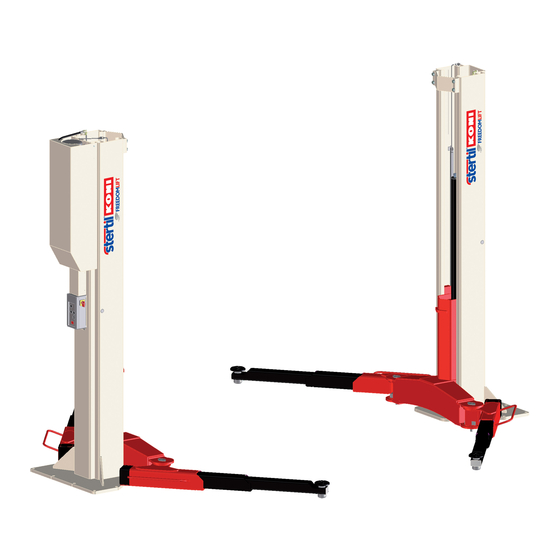
Introduction The Freedomlift is an electrically driven hydraulic column lift for lifting vehicles. Do not use the Freedomlift for purposes other than for which it is intended. This is not allowed and can be very dangerous. Requirements for service engineers Normal operation of the Freedomlift requires that service engineers: Installation and Service Manual SK 2055 / 2070 / 2090... -
Page 19: Training Levels
• have enough technical knowledge and experience to carry out the assigned tasks, • can recognize and prevent hazards, • have read this manual and understand the contents, • have been adequately trained, • are able to follow the procedures in this manual. The owner must ensure that employees are qualified and trained to perform all activities involved. -
Page 20: Description
Description The Freedomlift SK 2055 / 2070 / 2090 is designed for lifting vehicles. Overhead connection Attachment overhead connection Cover power unit Installation and Service Manual SK 2055 / 2070 / 2090... -
Page 21: Technical Specifications
Control box Column 1 Locking mechanism Extended Flex Arms Extended Flex Arms Adaptor Double telescopic arms 10. Adaptors and extensions (optional) 11. Locking mechanism telescopic arms 12. Potentiometer 13. Solenoid for pawl 14. Telescopic arms 15. Column 2 16. Guide piece 17. -
Page 22: Product Specification
SK 2055 SK 2070 SK 2090 Control voltage 24 V DC 24, V DC 24 V DC 1.0 mm 1.0 mm 1.0 mm Hose rupture valve adjustment Raising and 39/39 s 58/58 s 58/58 s lowering times 78/39 s (single 116/58 s (single 116/58 s (single phase) - Page 23 This type plate is located inside the shelter on the bottom right corner of the right hand side panel. The following data are present on the type plate: Data Meaning Serial number Model description Type description Lift capacity of lift Nr.
- Page 24 System Specifications The design has been calculated to enable a maximum load on any one arm of: • SK 2055: 2060 kg • SK 2070: 2625 kg • SK 2090: 3375 kg Lifting This hydraulic 2-post vehicle lift is equipped with a single system hydraulic unit (on post I).
- Page 25 Elevation differences may be caused by oil leakage in cylinders or valves. Installation and Service Manual SK 2055 / 2070 / 2090...
-
Page 26: Installation
Installation Proceed as described next when unpacking and setting up the Freedomlift. Ensure that all packaging materials have been removed before starting the setup of the Freedomlift. Inspect the parts for any damage and/or missing smaller parts. Always report damage or missing parts to Stertil B.V. or your dealer and wait with the setup until a suitable solution has been obtained. - Page 27 SK 2090 Consult an expert if the floor does not comply with the required specifications. The foundation and anchors must comply with the following requirements: Thickness of concrete foundation: • SK 2055: at least 150mm • SK 2070: at least 175 mm •...
- Page 28 Only chemical anchors may be used for securing the vehicle lift. SK 2055: • UPAT-UKA chemical anchors (80 Nm torque), 12 pieces. • ASTA M16x250 anchor rod. • UKA 3 EAP M16 capsule (18 drill, 135 mm deep). SK 2070: •...
- Page 29 SK 2070 - SK 2090 Pouring a new foundation. If the conditions specified above have not been met, a new foundation needs to be poured in accordance with the following specifications: Volume of the concrete: • SK2055: 5 x 2,5 x 0,15 = 1.9 m3 •...
- Page 30 It is the responsibility of the user to determine whether the concrete floor is of sufficient quality. If the vehicle lift is being installed in an area at risk of frost, a frost-protection sill plate should be fitted around the edge of the foundation. 5.1.1.1 Installing the chemical anchors The Freedomlift must be installed on a concrete floor that:...
-
Page 31: Supplying Electrical Power
Do not secure the chemical anchors yet; this can only be done after the manufacturer's prescribed hardening time has elapsed. After the prescribed hardening time has elapsed, check the holding power of the anchor bolts by applying a torque of 60 Nm (SK 2055) or 125 Nm (SK 2070 and SK 2090). -
Page 32: Setting Up The Freedomlift
5.1.3 Setting up the Freedomlift For correct set up of the vehicle lift, the floor must comply with the requirements specified in Foundation on page 26. Ensure that the position of the chemical anchors is as prescribed in Installing the chemical anchors on page 30. Unscrew the clamping blocks (2) of the transport frame (1). - Page 33 Post 1 Post 2 Attach the hoisting eye (5) (part no. 61001008) to the post at approx. 20 cm from the top. Post Clamping block Chain Chain hook Hoisting eye Installation and Service Manual SK 2055 / 2070 / 2090...
- Page 34 Attach the hoisting equipment to the hoisting eye of post I. Set post I upright above the chemical anchors that have already been placed in the floor. One post weighs around 800 kg. The posts should only be lifted using appropriate hoisting equipment attached to the hoisting eye at the top of the post.
- Page 35 Check with a level that also the supports are at the same height. The post may recline max. 12 mm backward. If required adjust with shims. Tighten the nuts with a torque of 80 Nm (SK 2055) or 150 Nm (SK 2070 and SK 2090).
-
Page 36: Assembling The Hydraulics And Electricity
11. If desired, the perimeter of the base plates can now be sealed with silicone mastic. 5.1.4 Assembling the hydraulics and electricity Take care when fitting hydraulic components. All components must be free of dirt. Use clean UNIL SX 15 oil for the hydraulic system, filtered at a maximum of 4 microns. - Page 37 Determine what height the overhead wiring needs to be at and adjust the vertical connecting tubes (2) to the correct length if necessary. Pull the hydraulic hose and electrical cables through the tubes (1 and 2) and supports (3). The hydraulic hose's elbow joint should be attached to the hydraulic unit of post I and the two loose cables need to be connected up to post II.
-
Page 38: Assembling The Supporting Arms
Wiring for post II Cable clamp Plugs for control valves Wiring for post I Cable in cable trough Control box Unlocking solenoid Potentiometer 10. Fix the cables using cable ties. 11. Attach the housing to the hydraulic power unit. 12. Connect the control box to the power supply. 5.1.5 Assembling the supporting arms 5.1.5.1... - Page 39 T handle Locking pin Arm retraining washer Arm retainer Disk Guide piece Hinge pivot Distance bush Place the arm (4) in the guide piece (7). Place the upper arm retainer (5). Installation and Service Manual SK 2055 / 2070 / 2090...
- Page 40 Place the hinge pivot (8) and fix it in position using two disks (6) and two M12 hexagonal socket screws. Insert the locking pin (2) through the holes in the guide piece (7) and the upper arm retainer (5) and fix it in position using an M8 hexagonal-socket grub screw in the upper arm retainer.
- Page 41 Washer Pressure spring Push-rod Hinge pivot Half of arm retainer Half of arm retainer Place the arm retainer halves (8 and 9) in the arm. Fit the arm between the guide piece's hinge plates. Fit the hinge pivot (7). Attach the push-rod (6) and pin (5). Assemble the pressure spring (4) and peg (3).
-
Page 42: Operating Mechanism
Operating mechanism The vehicle lift works with two cylinders connected up in parallel. The maximum operating pressure is: • SK 2055: 180 bar • SK 2070: 210 bar • SK 2090: 260 bar Synchronous displacement in both cylinders is monitored electrically and corrected if necessary by means of an electronic/hydraulic system. -
Page 43: Performance When Starting Up
It is not possible to operate Down at the same time as Up is in operation, and vice versa. If a second control box is fitted, only one box can be operated at any time. The leds in the push buttons are linked to the outputs; they light up to indicate that the output in question is being driven. -
Page 44: Elevation Control
• All outputs are switched off if an elevation difference greater than 60 mm is detected, whether the vehicle lift is in operation or idle. • The lowering and unlock functions are disabled whenever an elevation difference greater than 30 mm arises. Raising remains possible. •... -
Page 45: Adjustment
If the deviation exceeds 3%, the display will show error code 16 See Error messages on page 72. If the same error code persists after further readings, replace one of the potentiometers. Differences in the elevation between the two posts can arise through temperature differences, elastic compression and slight internal leakage in the system. -
Page 46: Adjusting The Pawls
slightly using programme code 64. See Code 64 - Master and slave correction on page 48. • The code on the display in the control box can be set to the correct status by moving one of the set pins in one of the guide pieces. Adjusting the pawls Verify that the pawl (6) is engaged in the ratchet bar (7). -
Page 47: Programmable Settings
Programmable settings In general, programming is done as follows: When turning on the mains switch, press the Unlock button in until 60 (blinking) appears in the display code. Press the Up and Down buttons to select one of the programmes 60 through to 68. -
Page 48: Code 61 - Automatic Lighting
If the required elevation is higher than the current setting, deactivate the current elevation limiter first. Code 61 - Automatic lighting This option can be used to switch the lights on and off at heights below approximately 500 mm. The lights will turn on and off automatically if programme 61 is activated. -
Page 49: Code 66 - Potentiometers Disabled
This setting remains active for 10 minutes, after which the safe limit monitoring is automatically reactivated. The setting will not be saved in the EEPROM, which means that the safe limits will always be active after starting and stopping. Code 66 - Potentiometers disabled This option allows the functioning of the potentiometers to be checked. -
Page 50: Code 68 - Second Control Box
Code 68 - Second control box If a second control box is used (optional), code 68 must be activated in the second control box. Installation and Service Manual SK 2055 / 2070 / 2090... -
Page 51: Commissioning
Commissioning The checks and adjustments described in this chapter must be carried out by a service department engineer before the vehicle lift is put into service. There must be no vehicle on the vehicle lift during the checks and adjustments. Locking mechanism The locking pawls must be able to engage freely in every tooth of the ratchet bar. -
Page 52: Correction System
Correction system Position the arms approximately 200 mm above the ground. The correction is always to the highest side. Lower the guide piece for post I by approximately 40 mm using programme code 64 and the Down button. See Code 64 - Master and slave correction on page 48. -
Page 53: Cylinder Bleeding
When working, the temporary mains power connection can be disconnected, and the cable channels fastened using spacer bushings, screws and rings. Cylinder bleeding The cylinders are fitted with an SW10 nipple for bleeding air at the top. While raising, turn the nipples once round to loosen them and wait until there is a constant flow of oil without air bubbles. -
Page 54: Inspection And Maintenance
Inspection and maintenance Aim of maintenance Maintenance can be divided into two categories: • Preventive maintenance. • Corrective maintenance. Preventive maintenance is necessary to keep the machine in a good condition or returning it to that condition. Corrective maintenance is done after malfunctions have occurred. -
Page 55: Pay Attention To Safety
9.2.1 Pay attention to safety When carrying out inspection and maintenance, always set the Freedomlift to the lowest position and switch off the mains power supply switch (position 0). Secure the switch using a padlock. If the Freedomlift is in a higher position, always lower it into the safety lock. Always pay attention to safety. -
Page 56: Waste Disposal
9.2.3 Waste disposal Remove and dispose in a correct manner lubricating agents, used chemical products and other such matter. On this subject, the local environmental recommendations should be respected. See also Disposal on page 16. 9.2.4 Forms and administration It is recommended to keep a record for each periodic maintenance procedure performed on your equipment. -
Page 57: Lubrication
When Action Reference Yearly Service engineer: Check the hydraulic oil level. If necessary, check the oil level more often. Yearly Service engineer: Clean Cleaning on page 59 cylinders, pump unit and control box. Yearly Service engineer: Check if all moving parts run smoothly. -
Page 58: Replacing Hydraulic Oil
Do not attempt to apply oil or grease to any component not mentioned in a maintenance procedure or schedule. Contact your supplier/dealer if you discover an irregularity with the lubrication of any part. Replacing hydraulic oil Replace the hydraulic oil in the tank approximately once every 2 years. Set the Freedomlift to the lowest position and drain off the oil. -
Page 59: Cleaning
The different types of oils should not be mixed. After draining the oil from the lift and refilling the system with new oil, a low mix percentage is allowed. Do not attempt to apply oil or grease to any component not mentioned in a maintenance procedure or schedule. -
Page 60: Replacing The Cylinder
Operators are not allowed underneath the Freedomlift for inspections, this may only be done by qualified personnel. Replacing the cylinder To remove the cylinder: Move the guide pieces to the lowest position. Remove the potentiometer wires from the guide pieces. Raise the guide pieces to the highest position. - Page 61 Connect the oil line. Use the lifting mechanism to raise the cylinder so that the adapter plate is just free of the guide piece. Fix the adapter plate in position using the two M10x40 mm hexagonal screws. Lift the guide piece to the maximum position and remove the supporting beam.
-
Page 62: Options
Options 10.1 Second control box A second control box is an option. To install the second control box: Isolate the first control box from the power supply. Remove all wires between the mains switch Q1 and the solenoid switch KM in the main box. - Page 63 Take care when fitting hydraulic components. All components must be free of dirt. Use clean UNIL HVC SX 15 oil for the hydraulic system, filtered at a maximum of 4 microns. Remove the hydraulic unit housing (the housing is secured by two safety bolts).
- Page 64 Determine what height the overhead wiring needs to be at and adjust the vertical connecting tubes (2) to the correct length, if necessary. Pull the hydraulic hose and electrical cables through the tubes (1 and 2) and supports (3). The hydraulic hose's elbow joint should be attached to the hydraulic unit of post I and the two loose cables need to be connected up to post II.
-
Page 65: Led Lighting
Control box Unlocking solenoid Potentiometer 10. Fix the cables using cable ties. 11. Attach the housing to the hydraulic power unit. 12. Connect the control box to the power supply. 10.2 Led lighting Led lighting is an option. Installation and Service Manual SK 2055 / 2070 / 2090... - Page 66 Parts 4 aluminium profiles with double sided tape 8 Led engines 4 light tubes 1 transformer 4 cables for luminaries 1 Column 1 1 Column 2 1 cable control box / transformer Bag of parts To install the led lighting: Degrease the columns on the side where the aluminium profiles will be placed.
- Page 67 Insert the cables (5) at the top of the aluminium profiles, with the short end down. Connect the cables (6 and 7) with the plug connector to the cables (5) and push the cables downwards until the small plug connectors are in front of the big holes.
- Page 68 12. Install the cable (8) in the transformer and connect it. See figure below. 13. Make the hole for the extra nut (9d) the top of the control box. 14. install the transformer (4) with the screws and washers (9c) on the mounting plate.
- Page 69 Take care when fitting hydraulic components. All components must be free of dirt. Use clean UNIL SX 15 oil for the hydraulic system, filtered at a maximum of 4 microns. Remove the hydraulic unit housing (the housing is secured by two safety bolts).
- Page 70 Remove the cap and connect the hydraulic hose to the hydraulic unit (post Remove the cap and attach the other end of the hydraulic hose to the line for the lifting cylinder (post II). Attach the electric cable in post I using the plugs for the control box. Thread the electric cables through the cable duct in the pillar and connect them to the cables in the cable trough (post II).
-
Page 71: Services
Services It is not necessary to remove the vehicle from the vehicle lift to resolve most malfunctions. However, it is strongly recommended that you do remove the vehicle if the vehicle lift is in the lowest position. Set the vehicle lift to its lowest position in the event of malfunctions or repairs. If the malfunction makes this impossible, then ensure that all pawls are engaged in the safety locks (lower without unlocking). -
Page 72: Emergency Lowering
11.1 Emergency lowering In an emergency where it is not possible to lower the vehicle lift from the control box, the vehicle lift can be lowered manually. The emergency lowering procedure must only be performed by persons who are trained in this procedure. 11.2 Error messages All malfunctions are indicated on the control panel. - Page 73 Error code Sticker Cause Solution Slave High Slave guide piece more Vehicle lift blocked. than 60 mm too high. Set the lift horizontal using programme code 65 (see Code 65 - Safe limits on page 48). Height limit Lift is stopped at the Adjust the elevation if necessary (software) programmed elevation.
- Page 74 Error code Sticker Cause Solution mm).Otherwise, replace potentiometers. UP push button Short circuit in PCB input. Turn off and on. error If it persists, replace PCB. DOWN push Short circuit in PCB input. Turn off and on. button error If it persists, replace PCB. UNLOCK push Short circuit in PCB input.
- Page 75 Error code Sticker Cause Solution Motor relay not Motor-relay contacts are Check the wiring from terminal switching stuck or refuse to switch. LC to the relay, and replace the relay if necessary. EEPROM write Error writing analogue Turn off and on. analogue fault values to EEPROM.
-
Page 76: Troubleshooting
Troubleshooting This chapter contains common faults en how to solve them. Only authorized personnel is allowed to carry out maintenance. Incorrect adjustments, repairs and maintenance can cause damage to goods or personal injury. Consult your dealer/supplier. 12.1 Common faults and solutions Vehicle lift cannot be raised. - Page 77 Cause Solution. No mains power/control power. Check the mains power/control power Pawls are not retracted from the safety locks. First raise the vehicle lift about 50 mm; see Operation sticker on the post. The electrically operated lowering valve on the No control current to the solenoid coil, or hydraulic unit will not open.
- Page 78 No mains power Cause Solution Mains switch is off. Turn mains switch on. Defective LEDs. Vehicle lift functioning Contact technical services. normally. No mains power. Get an approved electrician to resolve the malfunction. Fuse F3 defective. Replace the defective fuse 200 (315) mA slow-blow.
-
Page 79: Technical Support
12.2 Technical support If the tips provided in this chapter do not answer your question or solve your problem, please contact your local Stertil B.V. service department or distributor. For a complete list of Stertil B.V. distributors and local service departments, please refer to the website: www.stertil-dockproducts.com. -
Page 80: List Of Parts
List of parts The following sections will give an overview of the main assemblies and their components. Installation and Service Manual SK 2055 / 2070 / 2090... -
Page 81: Main Components
13.1 Main components Index Reference Description Remarks Column 1 See Column 1 on page Column 2 See Column 2 on page 35000350 Telescopic arm SK2070 / SK 2090 35010300 Double telescopic arm SK2055 35000300 Double telescopic arm SK2070 / SK 2090 35000390 Extended Flex Arms (EFA) SK2055 Installation and Service Manual... - Page 82 Index Reference Description Remarks 35000901 Mounting equipment arms SK2055 / SK 2070 / SK 2090 35000902 Mounting equipment EFA SK2055 35000900 Inter connection set top 35000905 Second control unit Adaptor models See Adaptors and extensions on page 104 35000908 Power socket 35000904 Inter connection set bottom 35000903 LED lighting 35000118 Tool tray...
-
Page 83: Column
13.2 Column 1 Index Reference Description Remarks 35010410 Column weld assembly SK 2055 35020410 Column weld assembly SK 2070 35030410 Column weld assembly SK 2090 35000250 Guide block SK 2055, SK 2070 35010250 Guide block SK 2055-EFA 35030250 Guide block SK 2090 35000410 Suspension frame... - Page 84 Index Reference Description Remarks 35010401 Height stop 35000220 Cylinder adaptor plate 35000750 Control box 3x400V 50Hz 35000751 Control box 3x230V 35000752 Control box 1x230V 68034618 Hydraulic unit SK 2055 3x230/400V 68034121 Hydraulic unit SK 2070 3x230/400V 68034126 Hydraulic unit SK 2090 3x230/400V 35010650 Hydraulic cylinder 35000605...
-
Page 85: Column 2
13.3 Column 2 Index Reference Description Remarks 35010410 Column weld assembly SK 2055 35020410 Column weld assembly SK 2070 35030410 Column weld assembly SK 2090 35000250 Guide block SK 2055, SK 2070 Installation and Service Manual SK 2055 / 2070 / 2090... - Page 86 Index Reference Description Remarks 35010250 Guide block SK 2055-EFA 35030250 Guide block SK 2090 34200116 Securing bush 35010401 Height stop 35000220 Cylinder adaptor plate 35010650 Hydraulic cylinder 35000605 Hydraulic line with connections 65003528 Hex. bolt M16x30 mm 65012409 Cyl. screw M10x40 mm 65055024 Washer M16 65055019...
-
Page 87: Guide Block
13.4 Guide block Index Reference Description Remarks 35030250 Guide block assembly SK 2090 35000250 Guide block assembly SK 2055, SK 2070 35010250 Guide block assembly SK 2055-EFA 35030200 Guide block weld assembly SK 2090 Installation and Service Manual SK 2055 / 2070 / 2090... - Page 88 Index Reference Description Remarks 35000200 Guide block weld assembly SK 2055, SK 2070 35010200 Guide block weld assembly SK 2055-EFA 35000110 Support block rear/top 35000120 Support block rear/bottom 35000139 Support block 41201150 Pawl 35000136 Pull rod 35000720 Cable in cable reel 1020.50.00.36 Guide part 35000103 Guide plate...
-
Page 89: Double Telescopic Arm
Index Reference Description Remarks M3x6 65051026 Self locking hex. nut M5 65055013 Washer M4 1038.40.04.50 Securing ring a45 65060065 Securing ring a65 1038.13.50.01 Self adhesive cable clip 35000115 Cover SK2.26 & SK2.30 35000117 Cover SK2055, SK 2070, SK 2090 SK2.16 & SK2.20 65003359 Hex bolt M8x12 65055018... -
Page 90: Telescopic Arm
Index Reference Description Remarks 35000330 Arm outer part 35000320 Arm middle part 35000310 Arm inside part 65225014 Cyl. screw/hex.socket M16x15 mm 37003501 Slider pad 13.6 Telescopic arm Index Reference Description Remarks 35000350 Telescopic arm 35000370 Arm outer part 35000360 Arm inside part 65225011 Cyl. -
Page 91: Flex Arm
13.7 Flex arm Index Reference Description Remarks 35000390 Set arms Left and right arm 35000391 Arm left assembly On drawing is left arm 35000392 Arm right assembly 35000393 Arm outside part left 35000394 Arm outside part right 35010320 Arm middle part 35010330 Arm inside part 35000301... -
Page 92: Double Telescopic Arms Sk 2055-2.16
Index Reference Description Remarks 65055018 Washer M8 DIN 125 A 13.8 Double telescopic arms SK 2055-2.16 Index Reference Description Remarks 35010300 Arm assembly 35010310 Arm outside part left 35010320 Arm middle part 35010330 Arm inside part 35000301 Pad adaptor 65760050 Securing ring 30003002 65025111... -
Page 93: Arm Connections (Double) Telescopic Arm
13.9 Arm connections (double) telescopic arm Index Reference Description Remarks 35000901 Arm connection parts 35000104 Bottom arm lock 35000105 Upper arm lock 35000130 Hinge pin 35000135 Locking shaft 66201102 Grip elesa-T-griff 35000132 Disc 65012445 Cyl. head screw M12x25 65214358 Adjustment screw M8x8 65025057 Countersunk bolt M12x30 35000116... -
Page 94: Arm Connections Flex Arms
13.10 Arm connections flex arms Index Reference Description Remarks 35000902 Connection parts EFA 1020.50.00.40 Arm lock upper part 1020.50.00.45 Arm lock bottom part 32040152 Locking pin 33000130 Hingepin 33000131 Bush 33500175 Cover plate 33500178 Compression spring 5100.08.05.00 Pin 65003283 Hex.bolt M6x12 mm 65055015 Washer M6 Installation and Service Manual... -
Page 95: Cylinder
13.11 Cylinder Index Reference Description Remarks 35010650 Hydraulic cylinder 34099000 Sealing set ST1055/60/4120 35010653 Cylinder tube 35010654 Piston rod 41206252 Piston 41206255 Rod guiding aza_005791 Ball 13,5 mm 68228005 Capsule vp-n-14-q40 68700451 Strait screw connection 68591810 Support ring 49.6x55x1.4 68510472 O-ring 47.22x3.53 mm 68554550 Rod seal PS1400550-Z80... -
Page 96: Hydraulic Unit
Index Reference Description Remarks 41206251 Cylinder bottom 34200601 Piston foot 13.12 Hydraulic unit Index Reference Description Remarks 68034618 Hydraulic unit SK 2055, 3x230/400V 68034121 Hydraulic unit SK 2070, 3x230/400V 68034126 Hydraulic unit SK 2090, 3x230/400V 68039051 Electric motor 50Hz,3x230/400V 68039065 Hydraulic pump SK 2055 Installation and Service Manual... -
Page 97: Interconnecting Lines
Index Reference Description Remarks 68039054 Hydraulic pump SK 2070 & SK 2090 68039092 Oil tank 15 liter plastic 68039058 Pressure relief valve SK2055/2070/2090 68308009 Valve 68039063 Spool 69039094 Flow control valve lowering 69039093 Flow control valve 32556904 Check valve 68039009 Tank connection clamp 68039004 Breather cap... - Page 98 Index Reference Description Remarks 35000910 Vertical tube 35000911 Horizontal tube 35000703 Cable connector A (pot- meter) 35000707 Cable connector B (valves and magnet) 35000603 Hydraulic hose 35000430 Tube support 35000703 Cable connector A 35000707 Cable connector B Installation and Service Manual SK 2055 / 2070 / 2090...
-
Page 99: Control Box
13.14 Control box 7,10 7,11 7,11 (for 69500020) (for 69500003) Index Reference Description Remarks 35000722 Control box Bottom 35000721 Control box Cover 60700116 Stickers 1x208/230V 35000702 Cable Control box - Connector A 35000706 Cable Control box - Connector B cablecarrier pil1 Installation and Service Manual SK 2055 / 2070 / 2090... - Page 100 Index Reference Description Remarks 35000701 Cable Control box - Motor 69062033 Connection nut M20x1,5 1420/220 Pflitsch 69062009 Cable gland M20x1,5 22052u13 red Pflitsch Dummy plug M20x1,5 Skindicht WN-M 52020523 69062008 Cable gland M20x1,5 22052u11 green Pflitsch 69062006 Cable gland M20x1,5 22052u8 grey Pflitsch 65099035 Quick release screw...
-
Page 101: Variants And Options
13.15 Variants and options The following sections will give an overview of the main assemblies and their components. Installation and Service Manual SK 2055 / 2070 / 2090... -
Page 102: Second Control Box
13.15.1 Second control box Index Reference Description Remarks 35000905 Second control Europe 35000770 Second control box Europe 35000425 Upper mounting frame 35000426 Lower mounting frame 35000423 Cover 65003359 Hex.bolt M8x12 mm 65003285 Hex.bolt M6x16 mm 65025087 Cyl.screw/crosshead M4x10 65051028 Self locking hex. nut M6 65055018 Washer M8 65055015... -
Page 103: Led Lighting
13.15.2 Led lighting Index Reference Description Remarks 69500019 Transformer 35000915 Cables 32709132 Plug with hole 69700110 Led-engine 69700061 Led-tube 35000912 ALU tube 69062033 Plug Installation and Service Manual SK 2055 / 2070 / 2090... -
Page 104: Adaptors And Extensions
13.15.3 Adaptors and extensions 5*** Index Reference Description Remarks 39225988 Adaptor ø128x36 Stdfor SK2070/2090 and SK2.20/2.26/2.30 35000304 Adaptor ø128x26 Stdfor SK2055 and SK2.16 37003935 Adaptor ø108x31 4310.09.05.00 Adaptor V 39225983 Adaptor toothed Stdfor SK2.16/2.20/2.26/2.30 4310.09.06.00 Adaptor U 4310.09.04.00 Adaptor flat 37003925 Support extension 250 Installation and Service Manual... - Page 105 Index Reference Description Remarks 37003916 Support extension 160 Stdfor SK 2.16/2.20/2.26/2.30 37003909 Support extension 90 Stdfor SK 2.16/2.20/2.26/2.30 35000306 Support extension 35 Stdfor SK 2.16/2.20/2.26/2.30 Installation and Service Manual SK 2055 / 2070 / 2090...
-
Page 106: Appendices
Appendices 14.1 Hydraulics diagram • A: Control valve • B. Flow limitation valve for lifting • C. Flow limitation valve for lowering Installation and Service Manual SK 2055 / 2070 / 2090... - Page 107 • D. Pressure relief valve • E. Non-return valve • F. Suction filter • G. Hose rupture valve • H. Lifting cylinder • I. Bleeding/filler cap • J. Stop • M. Electric motor • P. Pump Installation and Service Manual SK 2055 / 2070 / 2090...
-
Page 108: Electrical Diagram 3 X 230V
14.2 Electrical diagram 3 x 230V Installation and Service Manual SK 2055 / 2070 / 2090... -
Page 109: Electrical Diagram 3 X 400V
14.3 Electrical diagram 3 x 400V Installation and Service Manual SK 2055 / 2070 / 2090... - Page 110 14.4 Table electrical diagram / control box Index Description Remarks Control box with foil-covered switching panel PCB plate Mains switch Solenoid switch 200mA slow-blow fuse 400V control box 315mA slow-blow fuse 230V control box F1/2 5A slow-blow fuse Motor Transformer Acoustic alarm E1/2 Lights (option)
- Page 111 Index Description Remarks Unlocking LED DOWN LED Yellow Grey Pink White Green Black Blue Brown Y/GR Yellow/green Installation and Service Manual SK 2055 / 2070 / 2090...
-
Page 112: Dimensions Sk 2055 - Extended Flex Arms
14.5 Dimensions SK 2055 - extended flex arms Installation and Service Manual SK 2055 / 2070 / 2090... -
Page 113: Dimensions Sk 2055 - 3-Piece Arms
14.6 Dimensions SK 2055 - 3-piece arms Installation and Service Manual SK 2055 / 2070 / 2090... -
Page 114: Dimensions Sk 2070 / Sk 2090 - 2-Piece Arms
14.7 Dimensions SK 2070 / SK 2090 - 2-piece arms Installation and Service Manual SK 2055 / 2070 / 2090... -
Page 115: Dimensions Sk 2070 / Sk 2090 - 3-Piece Arms
14.8 Dimensions SK 2070 / SK 2090 - 3-piece arms Installation and Service Manual SK 2055 / 2070 / 2090... - Page 116 INDEX Acoustic signal • 12 Keep a record • 56 Adequately trained • 18 Assistance • 9 Legal ordinances • 8 Lifting cylinder • 36 Capacity • 21 Local laws • 7 Column 1 • 20 Local regulations • 8 Column 2 •...
- Page 117 Safety features • 12 Safety precautions • 9 Safety shoes • 16 Shut-down • 13 Static electricity • 14 Static test • 53 Store the manual • 6 Suggestions • 9 Technical knowledge • 18 Technical specifications • 21 Telescopic arms • 20 Thickness of foundation •...
- Page 118 Manufactured by: Stertil B.V. P.O. Box 23 9288 ZG Kootstertille (The Netherlands) Telephone: +31 (0) 512 334 444 Fax: +31 (0) 512 332 638 Email: info@stertil.nl Website: www.stertil.nl...
Need help?
Do you have a question about the Freedomlift SK 2055 and is the answer not in the manual?
Questions and answers