
Related Manuals for Sacher Lasertechnik Pilot PC

Summary of Contents for Sacher Lasertechnik Pilot PC
- Page 1 Sacher Lasertechnik Group Pilot PC Laser Driver User Manual http://www.sacher-laser.com...
- Page 2 The warranty period begins on the date of delivery or on the date of Group installation if installed by Sacher Lasertechnik This warranty is in lieu of all other guarantees expressed or implied and does not cover incidental or consequential loss.
-
Page 3: Table Of Contents
Group Sacher Lasertechnik Content General Information General Description ............ 2 Block Diagram ............3 Environmental Setting Up Conditions ......6 Rear Side ON/OFF Keyswitch........6 Other Laser Safety Components ......... 6 Getting Started ............7 Interlock Port ............12 PE Switch..............13 Housing Description Front Panel .............. - Page 4 Group Sacher Lasertechnik Operation of Laser Diode Controller Appendix Connector Schematics..........45 Error Codes ............... 52 Safety Symbols ............53 Fuse Replacement and Voltage Selection....54 Declaration of Conformity ........55 Technical Support ............. 56 User Manual Laser Diode Controller PilotPC...
-
Page 5: General Information
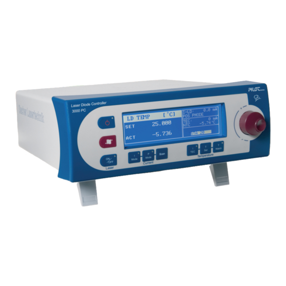
Group Sacher Lasertechnik General Information General Description The PilotPC Laser Driver is a highly precise controller for laser diodes. The laser current or the optical output power and the temperature of the connected laser diode can be precisely regulated. In case of the piezo option also the piezo voltage could be controlled. -
Page 6: Block Diagram
Group Sacher Lasertechnik Block Diagram Simplified Laser Current Control Block Diagram As shown in the block diagram the laser current source is controlled by the uController. Current control loop and power control loop is build in hardware. Only the set values are given by special DAC units. The... - Page 7 Group Sacher Lasertechnik Simplified Temperature Control Block Diagram The main temperature control blocks are build in software. This has some advantages for the user. - free programmable PID Setup - free programmable current limit Also some diagnostic features are implemented to protect the laser...
- Page 8 Group Sacher Lasertechnik Piezo Control Block Diagram The piezo driver is an option for the PilotPC useful for many TDLS. It can be equipped with the original configuration or upgraded at a later point of time. When the piezo driver is installed the PilotPC will automatically detect the board and activate the additional menus which are available under the “Scan”...
-
Page 9: Environmental Setting Up Conditions
Group Sacher Lasertechnik Environmental Setting Up Conditions The Laser Driver should placed in horizontal condition. The user must take care that the Key Switch is not blocked (could easily reached by the user) The user must take care that the fan output on the rear side is not blocked. -
Page 10: Getting Started
Group Sacher Lasertechnik Getting Started The laser system consists of an electronic controller unit – the PilotPC – and an external laser head. This configuration allows flexible use of the laser system possible since the laser head can be positioned freely in an optical setup. - Page 11 The laser diode is connected over the “LASER CONNECTOR” on the rear panel of the driver. To get the full performance and safety please only connect a special laser head from Sacher Lasertechnik. These laser heads incorporate several features. - Short circuit relay for the laser diode...
- Page 12 Group Sacher Lasertechnik Configuration 2 Laser Diode Laser Diode Controller Constant Current/Power Controller Safety 1 = Interlock Relay Control 2 = Photodiode Cathode 3 = Ground for Laser Diode 4 = Photodiode Anode Interlock 5 = GND for Interlock Control...
- Page 13 Group Sacher Lasertechnik Configuration 4 (common anode) Laser Diode Laser Diode Controller Constant Current/Power Controller Safety 1 = Interlock Relay Control 2 = Photodiode Cathode 3 = Ground for Laser Diode 4 = Photodiode Anode Interlock 5 = GND for Interlock...
- Page 14 Group Sacher Lasertechnik TEC / Temperature Sensor Configurations TEC and temperature sensor are connected over the “TEC CONNECTOR” on the rear panel. The laser driver supports two different types of sensor. - AD590 (temperature Transducer) - 10K NTC (Thermistor) The sensor could be selected in the “Temp Setup Menu”...
-
Page 15: Interlock Port
Group Sacher Lasertechnik Interlock Port The interlock port is one of several safety features. The port acts as input port for a safety contact and as an indicator port which could drive a LED. The port is internally hardwired to the laser power supply so that an open interlock loop will directly cause a shut down of the laser. -
Page 16: Pe Switch
Group Sacher Lasertechnik PE Switch The PE switch is used to improve the noise behavior of the laserdiode current source. In some cases, especially when external measurement equipment is connected to the laserhead or the laserdriver, line frequency noise comes up. -
Page 17: Housing Description
Group Sacher Lasertechnik Housing Description User Manual Laser Diode Controller PilotPC... -
Page 18: Front Panel
Group Sacher Lasertechnik Front Panel This section shows the front-panel elements. The front panel consists of a blue graphic display and a foil keypad- List of Front panel Elements Element Description Line Button To switch the driver ON/OFF Graphic Display... -
Page 19: Rear Panel
Group Sacher Lasertechnik Rear Panel This section shows the rear panel elements. On this side you find all connectors. List of Rear Panel elements Element Description RS232 Interface Connector GBIB Interface Connector PE Switch Safety Interlock Connector Key Switch USB Interface Connector... -
Page 20: Rear Panel Piezo Option
Group Sacher Lasertechnik Rear Panel Piezo Option This section shows the rear panel elements. On this side you find all connectors. List of Rear Panel elements Element Description RS232 Interface Connector GBIB Interface Connector PE Switch Safety Interlock Connector Key Switch... -
Page 21: Menus
Group Sacher Lasertechnik Menus Level II Menu structure The menus are organized in a top down tree structure with 4 levels. Main Menu I-Mode P-Mode Scan Temperature Scan Setting Laser Setting Temp Setting System Setting Laser Setup Scan Setup Temp Setup... - Page 22 Group Sacher Lasertechnik Level IV Setup Menus protected level to adjust limit parameters or parameters witch could cause a damage of the laser system User Manual Laser Diode Controller PilotPC...
- Page 23 Group Sacher Lasertechnik Menu buttons The menu button is used to navigate between the different menus. Menu Leve II Level III Menu Level II Mode buttons The menus are organized in a top down tree structure with 4 levels. Level II menus are reached by pressing one of the mode buttons.
- Page 24 Group Sacher Lasertechnik Laser, TEC and System status field gives the user an direct overview in every mode. Laser Status Field Laser Status field shows the user the most important laser parameters. These are - Laser Current (in I-Mode) - Photodiode Current (in P-Mode)
- Page 25 Group Sacher Lasertechnik System Status P Z F G C C E M R M S T A 1 2 3 4 5 The system status field contains important labels which gives the user information about specific options and an error code which is generated by the driver diagnostic module.
-
Page 26: Main Menu
Group Sacher Lasertechnik Main Menu This menu is just to select level II sub menu. The jog dial is used to select the submenu and the jog dial button is to enter the menu. M a i n M e n u... - Page 27 Group Sacher Lasertechnik The following settings menu is displayed when the menu button is pressed. L a s e r S e t t i n g s Ext.Modulation Ext.Monitor LD-Curr PD Calibtation Table none IU Characteris. Mode Laser Setup ?
-
Page 28: Laser Setup
Group Sacher Lasertechnik Laser Setup In the laser setup menu the user will find critical parameters which could have influence on lifetime and reliability Therefore this parameters could be secured. When it is not allowed to change these settings the text “Secure” is displayed on top of the menu. -
Page 29: Iu-Scan Laser Setup
Group Sacher Lasertechnik IU-Scan Laser Setup In this mode a single laser scan is initiated. IU-Scan was build especially for a quick LD characterization. The user has first to setup the Start,Stop,Step values. With “Laser ON” the scan starts. The Laser driver stores Laser Current, Laser Voltage, Photodiode Current or Ext. -
Page 30: Ld-Power Menu
Group Sacher Lasertechnik LD-Power Menu I-LD: 1234,5 mA P h o t o d i o d e [ u A ] I-MODE -4000 mA S E T 1 2 3 4 . 5 AD590 21,00 °C PZ FG CC EM A C T - 1 2 3 4 . -
Page 31: Ld Temp Menu
Group Sacher Lasertechnik LD TEMP Menu In this menu the laser temperature set point and the actual temperature are displayed. I-LD: 1234,5 mA T e m p e r a t u r e [ ° C ] I-MODE -4000 mA S E T - 2 0 . -
Page 32: Temp Setup
Group Sacher Lasertechnik Temp Setup In the temp setup menu the user will find critical parameters which could have influence on lifetime and reliability Therefore this parameters could be secured. When it is not allowed to change these settings the text “Secure” is displayed on top of the menu. -
Page 33: Scan - Menu
Group Sacher Lasertechnik Scan - Menu In this menu the piezo functions are configured . In case that there is no piezo module installed only the current coupling settings are displayed. I-LD: 1234,5 mA P i e z o [ V ]... - Page 34 Group Sacher Lasertechnik Direction Sets current coupling direction Menu Jump to main menu System Jump to system menu User Manual Laser Diode Controller PilotPC...
-
Page 35: Current Coupling Setup
The laser driver of Sacher Lasertechnik provides an adjustable coupling between the piezo voltage and the injection current of the diode laser. -
Page 36: Diagnostic Menu
Group Sacher Lasertechnik Diagnostic Menu The diagnostic menu gives the user additional text information when an error occurs. The menu will be permanent updated. D I A G N O S E S T A 5 1 1 Laserhead Loop Open... - Page 37 Group Sacher Lasertechnik Beeper The bepper acts as acoustical warning when the laser is turned on and as error indicator. Error beeper messages could be deactivated in the SYSTEM SETTINGS or over remote interface. The following table explains the different cases.
- Page 38 Group Sacher Lasertechnik Remote Interfaces The driver is equipped with RS232 , USB and GPIB Interface. RS232 and USB lead internally to one connection, so it is not possible to use them simultaneously. µController RS232 Port USB Port GPIB Port...
-
Page 39: System Info Menu
Displays the operating hours of the laser current source (turn on time) Userkey Bootmode Is used if the firmware of the driver must be updated. This could be done with our Sacher Lasertechnik support team User Manual Laser Diode Controller PilotPC... -
Page 40: Driver Secure / Unsecure
This feature is installed to protect the lasersystem against user operating errors. When the driveris is in secure mode the following splash screen came up when th driver is switched on. Pilot PC 500 SW V4.00 opt.65C HW V4.00 LC Serial No. 0504001 Secure Thefollowing parameters could not be adjusted in “secure mode”... -
Page 41: Specifications
Group Sacher Lasertechnik Specifications Laser Diode Controller PilotPC 500 Current Source Drive Current Output Output Current Range: 0-500mA Setpoint Resolution: 0.1mA Setpoint Accuracy: ±0.1% of FS Noise: <5µA RMS Temperature Coefficient: <50ppm/°C Short-Term Stability (1 hr.): <20ppm Long-Term Stability (24 hr.): <50ppm... - Page 42 Group Sacher Lasertechnik Current Coupling Modulation Low Volt Input analog Range -20..+20V High Volt Input analog Range -120..+120V Low Volt Mode Transf: 28,2..310 mA/V High Volt Mode Transf: 4,7..51,7 mA/V (High Voltage Mode = Prescal ON) Bandwidth(3dB): 6kHz Laser Current Monitor *...
-
Page 43: Laser Diode Controller Pilotpc 3000
Group Sacher Lasertechnik Laser Diode Controller PilotPC 3000 Current Source Drive Current Output Output Current Range: 0-3000mA Setpoint Resolution: Setpoint Accuracy: ±0.1% of FS Noise: <20µA RMS Temperature Coefficient: <50ppm/°C Short-Term Stability (1 hr.): <20ppm Long-Term Stability (24 hr.): <50ppm... - Page 44 Group Sacher Lasertechnik Temperature Control TEC Output Output Type: Bipolar Constant Current Source Compliance Voltage: Maximum Output Current: -4A to 4A Current Limit Setpoint Accuracy:0.01A Maximum Power: Sensor Temperature Sensor: NTC or IC Temp Sensor AD590 Temp. Control Range : -5 to 30°C (AD590 and NTC)
-
Page 45: Laser Diode Controller Pilotpc 4000
Group Sacher Lasertechnik Laser Diode Controller PilotPC 4000 Current Source Drive Current Output Output Current Range: 0-4000mA Setpoint Resolution: Setpoint Accuracy: ±0.1% of FS Noise: <50µA RMS Temperature Coefficient: <50ppm/°C Short-Term Stability (1 hr.): <20ppm Long-Term Stability (24 hr.): <50ppm... - Page 46 Group Sacher Lasertechnik Temperature Control TEC Output Output Type: Bipolar Constant Current Source Compliance Voltage: Maximum Output Current: -4A to 4A Current Limit Setpoint Accuracy:0.01A Maximum Power: Sensor Temperature Sensor: NTC or IC Temp Sensor AD590 Temp. Control Range : -5 to 30°C (AD590 and NTC)
-
Page 47: Piezo Driver Option
Group Sacher Lasertechnik Piezo Driver Option The piezo driver is realized as a piggy back board which could be installed inside the PilotPC driver. Piezo Amplifier Output Drive Output Voltage Range: ±13.5V Output Voltage Accuracy: <10mV Offset Setpoint Resolution: Max. Output Current: 500mA Noise (0,01Hz ... -
Page 48: Appendix
Group Sacher Lasertechnik Appendix Connector Schematics Laser Connectors Laser Supply Cable to Laser Head (LD OUTPUT) Standard Sub-D9 FEMALE 1:1 connection rated for 5A. This connection is required. Pin Nr. Signal Name Description Interlock Photodiode Signal Minus LD GND Laser Diode Ground... - Page 49 Group Sacher Lasertechnik TEC Supply Cable to Laser Head (TEC OUTPUT) Standard Sub-D9 MALE 1:1 connection rated for 5A. This connection is usually required, but optional if temperature control is not needed. Pin Nr. Signal Name Description MGND AD590+ Temperature Sensor...
- Page 50 Group Sacher Lasertechnik IEEE488 (GPIB) Connector GPIB Remote Interface Connector Standard Centronics 24pol FEMALE connection This connection is only used for Remote Control Pin Nr. Signal Name Description DIO1 Data input /output DIO2 Data input /output DIO3 Data input /output...
- Page 51 Group Sacher Lasertechnik RS232 Connector RS232 Remote Interface Connector Standard Sub-D9 FEMALE connector. This connection is only used for Remote Control. Use a 1to1 cable for connection with a standard personal computer. Pin Nr. Signal Name Description TxD Output RxD Input...
- Page 52 Group Sacher Lasertechnik Modulation Connector I/P MOD The input is used for modulating the laser current or the laser power. MOD IN is a differential input. Pin Nr. Signal Name Description Signal + MOD P Modulation Plus Signal - MOD M...
- Page 53 Group Sacher Lasertechnik PZ / Function Generator Sync Output PZ Sync The output is used for triggering external devices. Pin Nr. Signal Name Description Signal + PZ SYNC P Modulation Plus Signal - PZ SYNC M Minus Piezo Connectors Piezo Connectors Both Piezo connectors are internally connected.
- Page 54 Group Sacher Lasertechnik Interlock Connector Interlock Safety Connector This connection is used for an external safety switch. It gives an opportunity to connect an external indicator lamp witch is switched on by the laser controller when the power stage is active.
-
Page 55: Error Codes
Group Sacher Lasertechnik Error Codes The onboard diagnostic module returns the system status and error flags. The error number is generated by the sum of each individual error number. The bits are octal coded ( refer to Table 4). The following table explains the error origin. -
Page 56: Safety Symbols
Group Sacher Lasertechnik Safety Symbols On the rear side you find a ground connector This connector is used as a measurement ground. The connector is not used for supplying the protective earth. User Manual Laser Diode Controller PilotPC... -
Page 57: Fuse Replacement And Voltage Selection
Group Sacher Lasertechnik Fuse Replacement and Voltage Selection On the rear side you find the fuse holder and voltage selector Fuse holder Voltage selector Fuse holder Voltage selector Fuse Replacment Follow these steps Remove the power cord Remove the fuse holder and replace the fuses... -
Page 58: Declaration Of Conformity
Group Sacher Lasertechnik Declaration of Conformity DECLARATION OF CONFORMITY We: Sacher Lasertechnik Rudolf-Breitscheid-Str . 1-5 D-35037 Mar bur g declare on our own responsibility, that the product: Kind of equipment: Laserdiodecontroller Type-designation: PilotPC Product Options: All Options is in compliance with following standard(s) or normative documents:... -
Page 59: Technical Support
Group Sacher Lasertechnik Technical Support Information and advice about the performance or operation of your laser is available from our application engineers. For quickest response ask for “Technical Support” and have your model and serial number available. Support is available by: Group Sacher –... - Page 60 Littman/Metcalf configuration as well as driver electronics for diode lasers and sophisticated measuring electronics. Sacher Lasertechnik was founded as a spin-off company of Marburg University in 1992. We started up with the manufacturing of anti-reflection coatings for diode lasers according to patent 6,297,066. Based an this key knowledge, we developed stable, narrow linewidth, wavelength tunable laser sources for spectroscopy, patent 5,867,512.
Need help?
Do you have a question about the Pilot PC and is the answer not in the manual?
Questions and answers