
Related Manuals for Quantel Ultra Big Sky Laser Series


Summary of Contents for Quantel Ultra Big Sky Laser Series
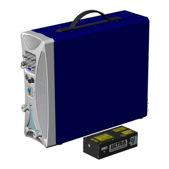
- Page 1 User Manual Ultra Version M | # DOC00040 April 22, 2012 Tough. Rugged. Reliable. Simply easy to use.
- Page 2 This manual is copyrighted by Quantel and all rights are reserved. This manual may only be reproduced with permission of Quantel. This manual is furnished for informational use only and is subject to change without notice. This manual does not imply any commitment on the part of Quantel or its business partners.
- Page 3 Service toll free: 1-800-914-8216 MANAGEMENT CERTIFICATION Fax: 1-406-522-2007 CustomerService@quantelusa.com www.quantel-laser.com Patrick Quero, April 22, 2012 Quality Director & Regulatory Affairs - Quantel Group User Manual Document # DOC00040 Version M April 22, 2012 This manual is provided in digital form to conserve paper.
-
Page 4: Table Of Contents
Contents CONTENTS Laser Safety 8.0 Operating Modes ......27 6.0 Laser Head with Dichroics ........ 1 532/355/266nm ......64 9.0 Manual Modes ......27 1.0 Hazard Information ....... 1 7.0 Laser Head with GRM & Dichroics 10.0 Automatic Mode (INT/INT) ..28 2.0 Terms &... -
Page 5: Laser Safety
Ultra Laser Safety | Contents LASER SAFETY 1.0 Hazard Information 3.0 Acronyms and Abbreviations Hazard information includes terms, symbols and instructions used in this AEL: Accessible Emission Limits manual or on the equipment to alert operating and service personnel to the BNC: Bayonet Neill-Concelman RF connector often used with coaxial cable recommended precautions in the care, use and handling of Class IV laser CFR: Compact Folded Resonator... -
Page 6: General Hazards
Ultra Contents | Laser Safety 4.0 General Hazards The following descriptions are of general hazards and unsafe practices that may result in product damage, severe injury or death. Other more specific warnings and cautions are presented as appropriate throughout this manual. DANGER This Class IV laser configures to emit 1064nm, 532nm, 355nm, 266nm, 213nm or 1574nm laser radiation. -
Page 7: Other Hazards
If for any reason a laser is rendered unusable and is not people of the potential risk that lies within the laser area. repairable, Quantel recommends that disposal of the system follow Only qualified people may operate the lasers. When not in use, all appropriate guidelines for such hazardous waste to prevent the lasers must be completely inoperable. -
Page 8: Additional Safety Information
Ultra Contents | Laser Safety 8.0 Additional Safety Information There are several public resources for good laser safety information. United States The American National Standards Institute (ANSI) Z136.1-2007 • document Safe Use of Lasers prescribes procedures intended to promote safety in using lasers. The document describes practices such as the appointment of a Laser Safety Officer (LSO), operation of the equipment only by trained personnel and in an area of limited access, equipment servicing only by trained and authorized personnel, and... -
Page 9: Safety Labels
Ultra Laser System. These labels are installed at the factory and should not be removed by the user. If for some reason a label is removed, obscured or damaged in any way, please contact Quantel for a replacement. NLO MODULE MVAT MODULE... -
Page 10: Ice450
Ultra Laser System. These labels are installed at the factory and should not be removed by the user. If for some reason a label is removed, obscured or damaged in any way, please contact Quantel for a replacement. 19” RACK ICE450 BACK PANEL ICE450 BACK PANEL... -
Page 11: Part/Serial Numbers
Ultra Safety Labels | Contents Have this serial number ready when you call customer service. 3.0 Part/Serial Numbers The Ultra Laser System has the following labels with product serial numbers and information: System Origination Labels • (located on the ICE450 upright or rack style) Part Number Labels •... -
Page 12: Setup
Ultra Contents | Setup SETUP 1.0 Mounting the Laser Head Note: See details for Setup and Operation of MVAT equipment under Optional Equipment on page Secure the Laser Head to a flat mounting surface using three (3) 6-32 UNC screws. It is important that the mounting surface be flat, to prevent distortion of the Laser Head and subsequent misalignment of the resonator. -
Page 13: Connecting
Ultra Setup | Contents 2.0 Connecting Standard Upright Ultra System CAUTION: Do not power up the laser system before thoroughly reading the installation and operation instructions. 1. Verify that the ICE key switch is turned OFF. 100-240 VAC, 2. Connect the I/O cable between the ICE rear panel 50/60 HZ POWER and the Laser Head. - Page 14 Ultra 10 | Contents | Setup Connecting a Rack ICE450 EMERGENCY STOP CAUTION: Do not power up the laser system before thoroughly reading the installation and operation instructions. 1. Verify that the ICE key switch is turned OFF. 2. Connect the I/O cable between the ICE rear panel and the Laser Head.
-
Page 15: Filling The Standard Ice450
Ultra | 11 Setup | Contents 3.0 Filling the Standard ICE450 10. Using the Remote Box System menu, set the pump to Normal mode. See Pump on page 26. CAUTION: Do not operate the system until it has been filled. Running 11. -
Page 16: Filling The Rack Ice450
Ultra 12 | Contents | Setup 4.0 Filling the Rack ICE450 10. Replace the fill/drain bottle reservoir cap and disconnect the fill/drain CAUTION: Do not operate the system until it has been filled. bottle from the ICE front panel. Running the pump without coolant may damage the pump. Running the pump without the Laser Head connected may result 11. -
Page 17: Functions
Ultra | 13 Functions | Contents FUNCTIONS 1.0 ICE450 Front Panel Controls BNC connectors Key Switch To turn the ICE450 ON, rotate the key to the ON (“I”) Serial interface position. With the Key Switch in the ON position, the laser (RS-232) port system is ready for use. - Page 18 Ultra 14 | Contents | Functions Lamp Out Interlock Out Q-Switch Out Interlock In Q-Switch In Lamp In Computer Serial Port Interface (RS-232) Figure 7: BNC Connector Locations ICE450 BNC Connectors Lamp Out: Interlock Out: Use this BNC output to connect an external laser- Use this BNC connector to synchronize with the laser flashlamp trigger signal.
-
Page 19: Ice450 Rear Panel
Coolant In 15S-HD, D-Sub connector provides fault interlock and port serial communications between the Master and Slave ICE450 in a dual enclosure PIV system. Contact Quantel Customer Service for more information. Fill port is down External I/O Port #1: The CBD25W3F, D-Sub mixed ICE450 on Side contact connector provides the interface to the Laser Head. -
Page 20: Operation
Ultra 16 | Contents | Operation OPERATION 1.0 Safety 3.0 Remote Interlock CAUTION: Obey all safety procedures described in the Safety This BNC Connector provides an interface for an external safety section of this manual. shutdown switch. The Remote Interlock can be connected to a lab door or other system outputs for safety purposes. -
Page 21: Manual Shutter
Ultra | 17 Operation | Contents 4.0 Manual Shutter CAUTION: If the manual shutter is in the horizontal OPEN position, it should be assumed that the laser is capable of lasing, regardless of any other status. Manual shutter is open when the handle is horizontal;... -
Page 22: Remote Box
Ultra 18 | Contents | Operation 5.0 Remote Box Flashlamp Press this button to stop flashlamp Stop operation. Emergency Stop Push this button to stop the Switch ICE450. It discharges the laser PFN Flashlamp Press this button to start flashlamp capacitor in less than 5 seconds. -
Page 23: Remote Box Navigation
Ultra | 19 Operation | Contents This arrow indicates return to the previous Flash Menu menu. User FL Counter Menu 6.0 Remote Box Navigation Main menu Flash Menu Main Menu >flash sync INT >reset counter configuration Use the LCD display to select Ultra Laser System functions. ct 0000.001.368 cu... -
Page 24: Remote Box Menu Detailed Descriptions
Ultra 20 | Contents | Operation 7.0 Remote Box Menu, Saving Configurations Detailed Descriptions The “save #” selection allows you to save a configuration. Saved After power-up and initialization, the Remote Box displays the Main menu. configurations preserve all the laser parameters in the ICE450 non-volatile memory. - Page 25 Ultra | 21 Operation | Contents Flashlamp Menu Select “cu” (user count) to show how many times the flashlamp To access the Flashlamp menu, from the Main menu, scroll to has fired since the “cu” parameter was reset by the user. It is “Flashlamp”...
- Page 26 Ultra 22 | Contents | Operation Q-Switch Menu To enter the “Q-Switch” menu from the Main Menu, scroll to “Q-Switch” AUTO mode: In “AUTO” mode the Q-Switch pulses on every and press the “Enter Menu” button. flashlamp pulse by default. An additional adjustment in “AUTO” mode is “QS pulse”.
- Page 27 Ultra | 23 Operation | Contents SCAN mode: Select Scan mode to specify a group or “scan” of BURST mode: Burst mode allows you to specify a group or “burst” of Q-Switch pulses that fire sequentially with every Q-Switch pulses to be repeated for a predetermined number of times or indefinitely.
- Page 28 Ultra 24 | Contents | Operation Scan Mode Example (scans 10, active 3, passive 2): With the To set the ramp settings, from the Q-Switch menu, scroll the cursor flashlamp running, press the “Q-Switch Start” button on the Remote to the “Ramp” item and press the “Enter Menu” button to show the Box.
- Page 29 Ultra | 25 Operation | Contents System Info Menu Temp Submenu items: From the Main menu, scroll to the “System Info” item and press the “Enter Menu” button to access the “System Info” menu items: System menu: Use the “Enter Menu” button to select this item to Main Menu return to the System Info menu.
- Page 30 Ultra 26 | Contents | Operation Time-out: This selection provides a submenu. With “Time-out” The Interlocks submenu contains the following items: enabled (ON) the ICE450 turns off the flashlamp simmer, flashlamp System menu fire and Q-Switch at user-defined time intervals. >IF1 00000000 To use “Time-out”: IF2...
-
Page 31: Operating Modes
Ultra | 27 Operation | Contents 8.0 Operating Modes The ICE450 provides three modes each for flashlamp firing and Q-Switching: • Manual Modes • Automatic Mode • External Modes 9.0 Manual Modes WARNING: Do not perform laser emission (Q-Switching) when Flashlamp Flashlamp ready button... -
Page 32: Automatic Mode (Int/Int)
Ultra 28 | Contents | Operation 10.0 Automatic Mode (INT/INT) Operating in Automatic Mode (INT/INT) Configuring Automatic Mode (INT/INT) To obtain continuous emission of laser pulses, from the Remote Box: To configure the ICE450 in Automatic mode: Flashlamp flash sync to INT. 1. - Page 33 Ultra | 29 Operation | Contents Divide By N (Auto-Ratio) Feature: This Q-Switch mode causes the Q-Switch to fire once for every specified number of flashlamp pulses. Internal flashlamp fire signal To use Divide By N (Auto-ratio): • From the Q-Switch menu, use the Auto Mode menu to increase the Auto-ratio value to a number greater than one.
-
Page 34: External Modes (Ext)
Contents | Operation 11.0 External Modes (EXT) WARNING: For GRM Laser Heads, Quantel configures the Pulse Repetition Frequency (PRF) at the optimum rate specified by the customer. For a GRM laser in External Mode, the PRF must be equal to the initial setting (within ±10%). - Page 35 Ultra | 31 Operation | Contents External Mode Triggering Methods The following pages describe the three different triggering methods for External Mode synchronization. The three methods for External Mode synchronization are using : • Flashlamp External Q-Switch Internal • Flashlamp Internal Q-Switch External •...
- Page 36 Ultra 32 | Contents | Operation Flashlamp Q-Switch Triggering Method Result Setting Setting External External An external source generates both the flashlamp Flashlamp trigger and the Q-Switch trigger. trigger input To use this mode:: 500 µsec processing delay 1. From the Main menu, select the Flashlamp menu.
-
Page 37: Example Start-Up Procedure
Ultra | 33 Operation | Contents 12.0 Example Start-Up Procedure WARNING: The following steps result in laser light emission from the output aperture of the Laser Head. During laser operation, everyone present in the laser room must utilize eye protection appropriate for the specific output wavelengths. -
Page 38: Decreasing Output Energy
Q-Switch to a value that is higher than optimal. You can do this using the Remote Box. CAUTION: Quantel advises against decreasing the energy of the flashlamp(s) to reduce the output energy. Decreasing the energy of the flashlamp(s) will cause a change in beam characteristics. -
Page 39: Software
Ultra | 35 Software | Contents SOFTWARE 1.0 Serial Interface The primary communications and control is via the RS-232 port lo- To send a command: Enter a command from the command set, cated on the ICE450 front panel (Rack ICE450 back panel). The ICE followed by a carriage return, CR (‘\r’, 0x0D) and line feed, LF can be set to lock out front panel key control and avoid conflict with (‘\n’, 0x0A), in that order. -
Page 40: Serial Command Reference
Ultra 36 | Contents | Software 2.0 Serial Command Reference Response Feature Operation Command Description format Fire, Internal Sync state string Sets the flashlamp into “Internal” sync mode and to start flashing. The response to this command is the state string Example: A... - Page 41 Ultra | 37 Software | Contents Response Feature Operation Command Description format Flashlamp Energy, query energy xx.yy J If the ICE450 has been configured to allow energy settings (using the “FSM” factory command), this command queries where “xx.yy” is the Example: EJ...
- Page 42 Ultra 38 | Contents | Software Response Feature Operation Command Description format Fire Q-Switch, set state string Starts the Q-Switching. The response to this command is the state string. Example: CC fire auto qs Fire Q-Switch Single Shot state string Initiates a single Q-Switch.
- Page 43 Ultra | 39 Software | Contents Response Feature Operation Command Description format Q-Switch Internal Sync QS sync: INT Sets the Q-Switch to Internal sync mode. QS sync: INT Example: QI Q-Switch External Sync QS sync: EXT Sets the Q-Switch to External sync mode. Example: QE...
- Page 44 Ultra 40 | Contents | Software Response Feature Operation Command Description format Q-Switch Auto Ratio, query QS rep-rate F/nn Queries or sets the Q-Switch auto ratio. In “Auto” mode with Internal Q-Switch sync selected, the Q-Switch will fire at a where “nn”...
- Page 45 Ultra | 41 Software | Contents Response Feature Operation Command Description format State, query “system state” Queries the system “state”. The response to this command is the “state string” that tells you the basic state of the laser, Example: ST fire ext qs e including: •...
- Page 46 Ultra 42 | Contents | Software Response Feature Operation Command Description format Status Word, query I a F b S c Q d This command is included for compatibility with the Brilliant ICE450. It queries for a code that indicates the state of the Example: WOR...
- Page 47 Ultra | 43 Software | Contents Response Feature Operation Command Description format Interlock Fault Byte 2, query IF2 ab cd ef gh The response string contains ASCII-encoded 1’s or 0’s indicating that either a fault or okay condition exists. Note: For more information about the interlocks, refer to Troubleshooting “1”...
- Page 48 Ultra 44 | Contents | Software Response Feature Operation Command Description format Q-Switch Interlock Byte, query IQS ab cd ef gh The response string contains ASCII-encoded 1’s or 0’s indicating that either a fault or okay condition exists. Example: IQS IQS 01 00 00 00 “1”...
- Page 49 Ultra | 45 Software | Contents Response Feature Operation Command Description format All Three Temperatures, query T3 xxx yyy zzz Queries all three temperatures at once. Reports CG, SHG and CS temperatures in tenths of degrees Celsius in a single “xxx”...
- Page 50 Ultra 46 | Contents | Software Response Feature Operation Command Description format Configuration, query configuration n Queries the configuration number or sets a new configuration. where “n” is the stored Example: CFG configuration 1 configuration number Setting a configuration “n”, recalls a saved configuration Configuration, set CFGn from the nonvolatile memory (eeprom).
-
Page 51: Quick Reference
Ultra | 47 Software | Contents 3.0 Quick Reference Operation Command Operation Command Fire, Internal Sync Fire, External Sync Simmer Stop Flash Flashlamp Voltage Flashlamp Energy Fire Q-Switch Flashlamp Frequency Stop Q-Switch Fire Q-Switch Single Shot Q-Switch Internal Sync Q-Switch Delay Q-Switch Sync QSSYNC Q-Switch External Sync... -
Page 52: Technical Specifications
Ultra 48 | Contents | Technical Specifications TECHNICAL SPECIFICATIONS Quantel Environmental Conditions: reserves the right • Ambient temperature range: 10°C to 40°C for specified system performance to modify the specifications. specifications • Storage Temperature Range: 5°C to 50°C. without notice. -
Page 53: Data Summary Sheet
Ultra | 49 Technical Specifications | Contents 2.0 Data Summary Sheet Data Summary Your system was shipped with a Data Summary Sheet that lists important information about your system. Refer to your Data Summary Your info here System SN: Your info here Laser SN: Sheet for the specific values for minimum and maximum limits, System WO #:... -
Page 54: Rs-232 Cable Wiring
Ultra 50 | Contents | Technical Specifications 3.0 RS-232 Cable Wiring Communications Baud Rate 9600 Data Bits: 8 Stop Bits: 1 Parity: None RS-232 port Flow Control: None location Version M 22-April-2012... - Page 55 Ultra | 51 Technical Specifications | Contents Serial Connector Pin-out The host computer or serial converter device must incorporate a 9-pin D-Subminiature RS-232 connector (DE-9). The cable to the ICE450 should not exceed 20m for RS-232 applications. Note that many varieties of serial converters are available from third-party suppliers to convert from RS-232 to RS-485/RS-422, USB, Ethernet and so on, depending on your interface requirements.
-
Page 56: External Trigger Signal Req
Ultra 52 | Contents | Technical Specifications 4.0 External Trigger Signal Requirements Trigger Circuit 50Ω External triggering will not function properly unless the external signal applied to the ICE450 input connector meets the specified requirements: • The signal generator must be set up to drive the ICE450 50Ω input. Signal Generator ICE450 Figure 22 shows a signal generator driving the external trigger input of... -
Page 57: Timing Diagrams
Ultra | 53 Technical Specifications | Contents 5.0 Timing Diagrams (1/PRF) SEC 500 µs ≥100µs EXT TRIGGER IN See Data Summary Sheet for value Example: 135 µs 100µs LAMP SYNC 100µs Q-SWITCH SYNC 70µs LASER OUTPUT 8 ns Typical Timing Diagram Figure 25 Typical Timing Diagram (External Flashlamp/Internal Q-Switch) Note: See the Operations section... - Page 58 Ultra 54 | Contents | Technical Specifications Internal flashlamp fire signal ~ 100 – 120µs Flashlamp current ~ 120 – 150µs Rod fluorescence Adjustable to 500 µsec Q-Switch trigger pulse ~ 70ns ~ 5ns (FWHM) Laser output pulse Timing of Signals in Automatic Mode Figure 26 Timing Signals in Automatic Mode Version M 22-April-2012...
- Page 59 Ultra | 55 Technical Specifications | Contents Figure 27 Jitter: Laser Light Output with Respect to Q-Switch Sync Output Version M 22-April-2012...
-
Page 60: Optional Equipment
Ultra 56 | Contents | Optional Equipment OPTIONAL EQUIPMENT 1.0 Variable Attenuator (MVAT) The Ultra Laser System may be equipped with an adjustable variable attenuator. Both motorized and manual versions are available. The assembly is contained within the Laser Head and is isolated from dust, moisture and other external environmental factors. -
Page 61: Mvat Command Set
Ultra | 57 Optional Equipment | Contents 2.0 MVAT Command Set MVAT serial command protocol is: ;AT:[COMMAND] XX Note: When typing a command, do not type the brackets [ ]. Example: ;AT:TF 50.25 Feature Operation Command Response Description Echo, set 0 or 1 Turns on/off the “Echo”... -
Page 62: Hyperterminal Setup For Mvat
Ultra 58 | Contents | Optional Equipment 3.0 Hyperterminal Setup for MVAT Note: A terminal communications program is required for sending RS-232 commands to the MVAT. Use the steps below to set up HyperTerminal: The example shown here is using Windows XP ®... -
Page 63: Drawings
Ultra | 59 Drawings | Contents DRAWINGS 1.0 Cooling System Diagram Heat Exchanger Level Sensor Vent Port Flow Coolant Switch Reservoir Fill/Drain Port Cartridge Temperature Optional Heater Pump LASER HEAD Sensor ICE450 COOLING SYSTEM DIAGRAM: ULTRA LASER SYSTEM Version M 22-April-2012... -
Page 64: Laser Head, 1064Nm
Ultra 60 | Contents | Drawings 2.0 Laser Head, 1064nm 6-32 TAPPED MOUNTING HOLE SHUTTER (FROM BELOW - 3X) 2.725 69.22 1.500 38.10 .275 6.99 1/8" [3.175mm] ALIGNMENT PIN SLIP-FIT HOLE AND SLOT (FROM BELOW) OUTPUT APERTURE 3.3 [84] NITROGEN PURGE BEND ACCESS (BOTH SIDES) 2.05 52.2... -
Page 65: Laser Head, 532/355/266 Nm Ultra Stable
Ultra | 61 Drawings | Contents 3.0 Laser Head, 532/355/266 nm Ultra Stable 6-32 TAPPED MOUNTING HOLE (FROM BELOW - 3X) SHUTTER 2.725 69.22 1.500 38.10 .275 6.98 1/8" [3.175mm] ALIGNMENT PIN SLIP-FIT HOLE AND SLOT (FROM BELOW) OUTPUT APERTURE NITROGEN PURGE 3.3 [84] ACCESS (BOTH SIDES... -
Page 66: Laser Head With Grm, 1064Nm
Ultra 62 | Contents | Drawings 4.0 Laser Head with GRM, 1064nm 6-32 TAPPED MOUNTING HOLE SHUTTER (FROM BELOW - 3X) 2.725 69.22 1.500 38.10 .275 6.98 1/8" [3.175mm] ALIGNMENT PIN SLIP-FIT HOLE AND SLOT (FROM BELOW) OUTPUT 3.3 [84] APERTURE NITROGEN PURGE BEND... -
Page 67: Laser Head With Grm 532/355/266Nm
Ultra | 63 Drawings | Contents 5.0 Laser Head with GRM 532/355/266nm 6-32 TAPPED MOUNTING HOLE (FROM BELOW - 3X) SHUTTER 2.725 69.22 1.500 38.10 .275 6.98 1/8" [3.175mm] ALIGNMENT PIN SLIP-FIT HOLE AND SLOT (FROM BELOW) OUTPUT APERTURE 3.3 [84] NITROGEN PURGE BEND ACCESS (BOTH SIDES... - Page 68 Ultra 64 | Contents | Drawings 6.0 Laser Head with Dichroics 532/355/266nm 6-32 TAPPED MOUNTING HOLE (FROM BELOW - 3X) SHUTTER 2.725 69.22 1.500 38.10 .275 6.98 1/8" [3.175mm] ALIGNMENT PIN SLIP-FIT HOLE AND SLOT (FROM BELOW) HIGH PURITY APERTURE 3.3 [84] ROTATABLE RESIDUAL APERTURE...
-
Page 69: Laser Head With Grm & Dichroics 532/355/266Nm
Ultra | 65 Drawings | Contents 7.0 Laser Head with GRM & Dichroics 532/355/266nm 6-32 TAPPED MOUNTING HOLE (FROM BELOW - 3X) SHUTTER 2.725 69.22 1.500 38.10 .275 6.98 1/8" [3.175mm] ALIGNMENT PIN SLIP-FIT HOLE AND SLOT (FROM BELOW) HIGH PURITY APERTURE NITROGEN PURGE 3.3 [84] ROTATABLE... -
Page 70: Laser Head, 1574Nm Ultra Stable
Ultra 66 | Contents | Drawings 8.0 Laser Head, 1574nm Ultra Stable 6-32 TAPPED MOUNTING HOLE (FROM BELOW - 3X) SHUTTER 2.725 69.22 1.500 38.10 .275 6.98 1/8" [3.175mm] ALIGNMENT PIN SLIP-FIT HOLE AND SLOT (FROM BELOW) OUTPUT APERTURE 3.3 [84] NITROGEN PURGE BEND ACCESS (BOTH SIDES... -
Page 71: Laser Head With Mvat Ultra 1064Nm
Ultra | 67 Drawings | Contents 9.0 Laser Head with MVAT Ultra 1064nm 6-32 TAPPED MOUNTING HOLE (FROM BELOW - 3X) SHUTTER 2.725 69.22 1.500 38.10 .275 6.99 1/8" [3.175mm] ALIGNMENT PIN SLIP-FIT HOLE AND SLOT (FROM BELOW) OUTPUT APERTURE NITROGEN PURGE 3.3 [84] ACCESS (BOTH SIDES... -
Page 72: Maintenance
Ultra 68 | Contents | Maintenance MAINTENANCE Coolant 2.0 Draining the ICE450 Loop CAUTION: Inadequate cooling system Fill/Drain CAUTION: Remove ALL coolant. maintenance may result in coolant contamination tube Coolant trapped within the Power and/or system damage. Supply may freeze and cause 1.0 Scheduled Maintenance irreversible damage to the internal components. - Page 73 Ultra | 69 Maintenance | Contents 7. Connect the empty Fill/Drain bottle. The tube from the bottom of the bottle connects to the Fill/Drain port. The tube from the top of the bottle connects to the Vent port. 8. Hold the bottle lower than the ICE450 reservoir. Loosen the cap on the Fill/Drain bottle to allow the coolant to flow freely.
-
Page 74: Draining A Rack Ice450
Ultra 70 | Contents | Maintenance 3.0 Draining a Rack ICE450 CAUTION: Remove ALL coolant. Coolant trapped within the Power Supply may freeze and cause irreversible damage to the internal components. Note: It is useful to have a second person assist in draining the ICE450. - Page 75 • Green coloration may be a sign of organic contamination. CAUTION: All contaminants need to be removed from the coolant loop prior to operating the laser. Please contact Quantel USA if you suspect contaminated coolant. Refilling the Reservoir (unless transporting) 1.
-
Page 76: Replacing The Di Cartridge
Ultra 72 | Contents | Maintenance 4.0 Replacing the DI Cartridge The ICE deionization (DI) cartridge is located on the blue coolant line. This cartridge should be replaced every six months and each time the flashlamp is replaced to maintain coolant integrity. Deionizing the coolant helps maintain low coolant conductivity. -
Page 77: Transporting The System
The label next to the fuse holder lists the specified fuse type and rating. Use 5 X 20 mm, 10A, 250V T-LAG fuses, Bussmann S505-10-R or equivalent, Quantel part number: 70850123LF. CAUTION: Only replace the fuses with the specified fuse. Failure to do so may result in equipment damage or personal injury. -
Page 78: Flashlamp Replacement
Ultra 74 | Contents | Maintenance 7.0 Flashlamp Replacement Wear protective gloves or finger cots For optimal performance, the flashlamp should be replaced approximately every 50 million shots. See page 21 for information on viewing the shot counter. Note: Gradual lamp degradation is normal. Lamp degradation requires increases in input energy levels to maintain the original output level. - Page 79 If there is any doubt about this lamp insertion process, please call Quantel USA Customer Service Department. 3. Replace the lamp access cover by pushing and rotating it Resetting the Shot Counter clockwise.
-
Page 80: Nitrogen Purge For The Ultra
Ultra 76 | Contents | Maintenance 8.0 Nitrogen Purge for the Ultra The Laser Head has been factory purged with UHP (Ultra High Purity) dry nitrogen to prevent condensation on the laser optics. If any cover or access screw is removed for any reason, the Laser Head should be purged again with UHP nitrogen. -
Page 81: Nitrogen Purge For Fola
Ultra | 77 Maintenance | Contents 9.0 Nitrogen Purge for FOLA Unlike the Ultra Laser Head, the Fiber Optic Launch (FOLA) module is not hermetically sealed. A loss of nitrogen will occur naturally over time and especially if the laser is shipped from one locale to another or when the fiber is removed. -
Page 82: Troubleshooting
All other service or repair of the ICE450, Laser Head or Laser Head optical alignment issues require a qualified Quantel technician or trained Field Service Representative. Quantel Customer Service. Basic troubleshooting can help you resolve: www.quantel-laser.com... -
Page 83: Resolving Interlock Faults
If the shorting plug is OK, the issue may be an internal connection. Call Quantel Customer Service. IF1 00010000 Laser Head housing I/O cable is not Ensure the I/O cable is fully seated. - Page 84 ICE450. Call for technical assistance. IF1 00000100 controller bus error Problem in the Contact Quantel Customer Service. The ICE450 system controller has two controller system buses used to communicate with system relating to its internal circuitry.
- Page 85 Call Quantel Customer Service. Note: A temperature reading of 17.9°C indicates an open circuit. Notify Quantel Customer Service in this case. IF2 00100000 low coolant The coolant is not warm • Allow time for the coolant to warm.
- Page 86 See front and back panel labels. • The ICE450 is There may be a leak or the level-detect horizontal with the switch may be faulty. Call Quantel wrong side facing up Customer Support. IF2 00000100 low coolant flow • Coolant line is •...
- Page 87 Remote Box if the charge cycle is disabled before the microprocessor is notified. Refer to IF2 01000000 for details. If the error persists, please contact Quantel Customer Service. IF3 01000000 voltage over setting This indicates a...
- Page 88 Remote Box. increase the setpoint for frequency. An interlock condition occurs if they do not Contact Quantel Customer Service for match. details on disabling frequency checking. IF3 00001000 high frequency The external trigger...
- Page 89 Solution/Suggestion Description Value Message IQS 10000000 Q-S disabled This interlock does Contact Quantel Customer Service for This interlock is not used. If this value not prevent the laser repair. appears, contact Quantel Customer from firing. It prevents Service for repair.
-
Page 90: Serial Communications Troubleshooting
Ultra 86 | Contents | Troubleshooting 4.0 Serial Communications Troubleshooting The ICE450 has an important safety feature that may prevent serial communication during use of the Remote Box. Pressing any button on the Remote Box disables the serial port communications. To verify that this feature has not disabled serial communications, use the Remote Box System Info menu and ensure the Serial link item is set to ON. -
Page 91: Diagnosing Problems
Ultra | 87 Troubleshooting | Contents 5.0 Diagnosing Problems Problem Possible Cause Solution/Suggestion No power connected Check the simple things first—make sure the power cord is plugged into the outlet and making connection to the back of the ICE. Verify that the circuit breaker is allowing power to the outlet. Mains Power switch is OFF Verify that AC Mains power is ON by checking the Key Switch. - Page 92 If contaminated coolant is suspected, the cooling system must be purged and properly cleaned prior to operating the laser. Please consult Quantel for instructions on how to clean your cooling system if you suspect organically contaminated coolant. See Replacing the DI Cartridge on page 72 for information on coolant properties.
- Page 93 Ultra | 89 Troubleshooting | Contents Problem Possible Cause Solution/Suggestion Flashlamp is not enabled. Verify that both the Flashlamp “ready” light and the Flashlamp “start” light on the Remote Box are illuminated. Flashlamp is not in Internal Verify that Internal sync is selected in the Remote Box Flashlamp menu. Mode.
- Page 94 Verify that the coolant level is OK and fill if necessary. position. NOTE: Contact Quantel USA for any repair actions necessary beyond those described in this manual. Attempts to adjust, repair or replace any portion of the laser system may damage the system and void the warranty...
-
Page 95: Warranty
(c) Remedies are available only if QUANTEL USA is notified in writing by Buyer promptly upon discovery of any defects and Quantel Service Center France in any event within the warranty period for the individual goods, whereby Seller’s examination of such goods discloses to... -
Page 96: Certificates
Contents | Certificates CERTIFICATES CE Certificate of Conformance By affixing the CE marking, Quantel assures that the ICE450 meets all the essential requirements of all applicable European Union (EU) directives required for market placement in the European Economic Area (EEA). - Page 97 Dear Sir or Madam: We, Quantel USA hereby declare that product: Class IV Solid State Laser System, model(s): Rack with Ultra 20/50/100, Brilliant or Brio Laser Heads are electrically identical with the same electromagnetic emissions and electromagnetic compatibility characteristics as model: Rack with CFR 200/300/400 Laser Head tested by BACL, the results of which are featured in BACL project: R0804231.
- Page 98 www.quantel-laser.com...
Need help?
Do you have a question about the Ultra Big Sky Laser Series and is the answer not in the manual?
Questions and answers