Micronics U1000MKII-HM User Manual
Clamp-on ultrasonic flow meter, clamp-on ultrasonic heat meter
Hide thumbs
Also See for U1000MKII-HM:
- User manual (38 pages) ,
- User manual (42 pages) ,
- User manual (39 pages)
Table of Contents
Advertisement
Quick Links
U1000MKII
U1000MKII-FM: Clamp-on Ultrasonic Flow Meter
U1000MKII-HM: Clamp-on Ultrasonic Heat Meter
User Manual
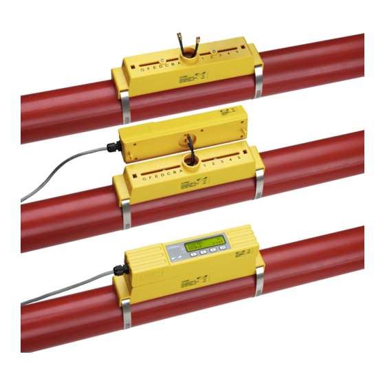
U1000MKII-HM shown
Micronics Ltd, Knaves Beech Business Centre,
Davies Way, Loudwater, High Wycombe, Bucks HP10 9QR
Telephone: +44(0)1628 810456
E-mail:
sales@micronicsltd.co.uk
www.micronicsflowmeters.com
Issue 3.1
Advertisement
Table of Contents

Related Manuals for Micronics U1000MKII-HM


Summary of Contents for Micronics U1000MKII-HM
- Page 1 U1000MKII U1000MKII-FM: Clamp-on Ultrasonic Flow Meter U1000MKII-HM: Clamp-on Ultrasonic Heat Meter User Manual U1000MKII-HM shown Micronics Ltd, Knaves Beech Business Centre, Davies Way, Loudwater, High Wycombe, Bucks HP10 9QR Telephone: +44(0)1628 810456 E-mail: sales@micronicsltd.co.uk www.micronicsflowmeters.com Issue 3.1...
-
Page 3: Table Of Contents
Pipe Adaptors ......................17 2.6.2 Attaching to Pipe ....................... 17 Remove Sensor-Holding Screws ..................18 Connect Electronics Module ..................... 19 Attach the Temperature Sensors (U1000MkII-HM Only) ........... 19 2.10 Normal Operation ......................21 2.10.1 U1000MkII-FM ......................21 2.10.2 U1000MkII-HM ......................21 2.10.3... - Page 4 4.1.1 Volumetric Pulse ......................30 4.1.2 Frequency Mode ......................30 4.1.3 Energy Pulse (U1000MkII-HM only) ................31 4.1.4 Flow Alarm - Low Flow ....................31 Flow Alarm – Signal Loss ..................31 4.1.5 4-20mA Current Output (U1000MkII-FM only) ..............31 Modbus (if fitted) .......................
-
Page 5: Introduction
• U1000MkII-HM is an ultrasonic clamp-on thermal, heat/energy meter. It uses ultrasound to measure flow rate and is also equipped with PT100 temperature sensors to measure flow and return temperatures. -
Page 6: How Does It Work
U1000MKII User Manual Micronics How Does It Work? The U1000MKII uses a cross correlation transit time algorithm to provide accurate flow measurements. An ultrasonic beam of a given frequency is generated by applying a repetitive voltage pulse to the transducer crystals. This transmission goes first from the downstream (blue) transducer to the upstream transducer (red) as shown in the upper half of Figure 1. -
Page 7: Package Contents
225-5005 (U1000 SMALL PIPE V CLAMP) p/n 225-5009 (U1000 VERY SMALL CIRCLE PIPE CLAMP) U1000MkII-HM only: Non-releasable stainless cable ties for temperature sensors (2) p/n 223-5005 Quick release clamps for use with pipes with an OD of 25-70mm (2) p/n 225-5007. -
Page 8: Display
U1000MKII User Manual Micronics Display The U1000MKII display comprises: • One 2-line x 16 character LCD with backlight • Four tactile key switches • Two LEDs Flow Signal strength Flow Units Flow Direction Measured flow. For accurate Units applicable to... -
Page 9: Quick Start Procedure
STAGE. THE ELECTRONICS MODULE CAN BE FULLY CLIPPED DOWN LATER ONCE ALL MEASUREMENTS HAVE BEEN CHECKED. U1000MkII-HM only: Plug in the temperature sensors to the Electronics Module (see page 19) and attach the PT100 sensors to the flow and return pipes (see Section 2.1.1, page 6). -
Page 10: Installation
IMPORTANT: DO NOT EXPECT TO OBTAIN ACCURATE RESULTS IF THE UNIT IS POSITIONED CLOSE TO ANY OBSTRUCTION THAT DISTORTS THE UNIFORMITY OF THE FLUID FLOW PROFILE (SEE PAGE 46). MICRONICS LTD ACCEPTS NO RESPONSIBILITY OR LIABILITY IF PRODUCT HAS NOT BEEN INSTALLED IN ACCORDANCE WITH THESE INSTRUCTIONS. -
Page 11: Clean The Pipe's Flow Sensor Contact Area
U1000MkII-HM: The area of pipe where the temperature sensors are to be attached must be free of grease and any insulating material. It is recommended that any coating on the pipe is removed so that the sensor has the best possible thermal contact with the pipe. -
Page 12: Pulse Output Connection
U1000MKII User Manual Micronics 2.2.2 Pulse Output Connection The isolated pulse output is provided by a SPNO/SPNC MOSFET relay which has a maximum load current of 500mA and maximum load voltage of 24V AC/DC. This output is suitable for SELV circuits only. - Page 13 Micronics U1000MKII User Manual Figure 8 Modbus cable wiring NOTE: ENSURE THE WHITE WIRES ARE CORRECTLY ASSOCIATED WITH THE BLACK & BROWN WIRES. THE BLACK/WHITE TWISTED PAIR IS FITTED WITH A BLACK SLEEVE TO DISTINGUISH BETWEEN THE BLACK/WHITE AND BROWN/WHITE PAIRS.
-
Page 14: M-Bus Connections (If Fitted)
U1000MKII User Manual Micronics Modbus Master Spur Length Cables of any specified length can be supplied to order. +V (+5V or +12V) 270Ω for +5V, 1KΩ for +12V 120Ω RS485+ 120Ω RS485- 270Ω Optional Ground GND (0V) Isolated Isolated Isolated... - Page 15 Micronics U1000MKII User Manual Figure 11 M-Bus cable wiring NOTE: ENSURE THE WHITE WIRES ARE CORRECTLY ASSOCIATED WITH THE BLACK & BROWN WIRES. THE BLACK/WHITE TWISTED PAIR IS FITTED WITH A BLACK SLEEVE TO DISTINGUISH BETWEEN THE BLACK/WHITE AND BROWN/WHITE PAIRS.
-
Page 16: Temperature Sensor Probes (U1000-Hm Only)
U1000MKII User Manual Micronics M-Bus Master Spur Length Cables of any specified length can be supplied to order. Optional Ground Isolated Isolated Isolated M-Bus M-Bus M-Bus U1000-Mk2 U1000-Mk2 U1000-Mk2 Figure 12 M-Bus wiring diagram 2.2.6 Temperature Sensor Probes (U1000-HM only) Two separate 4-core plug-in cables are provided for the Temperature Sensor Probes connections. - Page 17 Micronics U1000MKII User Manual U1000-HM Temperature Probe Wiring COLD White White White White Solder pin side U1000-HM Figure 13 U1000-HM Temperature Probe Wiring Issue 3.1 July 19 Page 13...
-
Page 18: Switch On
The initial screen sequence is different for the FM and HM models. 2.2.7 U1000MkII-FM Switch on the power to the Electronics Module. A Micronics start-up screen is displayed for 5 seconds followed by hardware and software version information. You are then prompted to enter the internal diameter of... -
Page 19: U1000Mkii-Hm
U1000MKII User Manual 2.2.8 U1000MkII-HM Switch on the power to the Electronics Module. A Micronics start-up screen is displayed for 5 seconds followed by hardware and software version information. You are then prompted to enter the internal diameter of Enter Pipe ID : the pipe: 050.0 mm... -
Page 20: Adjust Flow Sensor Separation
U1000MKII User Manual Micronics Adjust Flow Sensor Separation Using the separation code displayed by the Electronics Module (see page 14/15), take the Sensor Assembly and adjust the flow sensor separation accordingly: Figure 14 Loosen the flow sensor-holding screws (left); slide to correct position (right) Undo the screws 2-3 turns, sufficiently to loosen the flow sensors and allow sideways movement. -
Page 21: Pipe Adaptors
Micronics U1000MKII User Manual 2.5.1 Pipe Adaptors The diagrams below show how the adaptors are fitted. The top ‘V’ shaped adaptor clips onto the ends of the Sensor Assembly and this should be used with all pipes with an outside diameter less than 60mm. -
Page 22: Remove Sensor-Holding Screws
U1000MKII User Manual Micronics Using the hose clips provided, clamp the Sensor Assembly (and adaptors, if used) to the pipe at an angle of 45° to the top of the pipe. Experience has shown that the most consistently accurate results are achieved when the unit is mounted at this angle (see page 46). This minimises the effect of any flow turbulence resulting from entrained air along the top of the pipe and sludge at the bottom. -
Page 23: Connect Electronics Module
UNTIL YOU HAVE CHECKED OPERATION. Figure 21 Connecting the Electronics Module Attach the Temperature Sensors (U1000MkII-HM Only) IMPORTANT: THE TEMPERATURE SENSORS MUST BE BALANCED BEFORE INITIAL USE, USING THE PROCEDURE DESCRIBED BELOW AND USED WITH THE CABLE LENGTH SUPPLIED. EXTENDING OR SHORTENING THE CABLES WILL NEGATE THE CALIBRATION OF THE SENSORS. - Page 24 U1000MKII User Manual Micronics To ensure an accurate temperature differential: Plug the temperature sensors into the Electronics Module and place them touching each other for 1 minute. Enter the password controlled menu and scroll to the Calibration sub-menu (see page 28).
-
Page 25: Normal Operation
The signal strength should be at least 120.00 l/min 40% for reliable operation. 2.9.2 U1000MkII-HM Press The unit checks for a valid flow signal. Checking Signals Searching... If a valid signal is found, signal strength and flow rate Sig:98% are displayed. -
Page 26: Troubleshooting The Flow Reading
If the unit is working correctly, clip the Electronics Module onto the Sensor Assembly. Secure in place with the screw on the right side (see page 43, Figure 24). Figure 23 Fully assembled U1000MkII-HM unit Page 22 Issue 3.1 July 19... -
Page 27: Menus
Micronics U1000MKII User Manual MENUS The password-protected menus allow you to change the default settings: • Setup (see page 24) • Modbus (see page 25) – if Modbus output option installed • M-Bus (see page 25) – if M-Bus output option installed •... -
Page 28: Setup Menu
U1000MKII User Manual Micronics Setup Menu NOTE: SCREENS WITHIN THE RED BOX ARE ONLY SHOWN ON U1000MKII-HM MODELS DURING INITIAL SETUP (SEE PAGE 14/15). If “inches” is selected for the Select Dimensions option, then Range 0.79 – 6.50 the temperatures will be displayed in °F and the energy... -
Page 29: Modbus Menu
Micronics U1000MKII User Manual Modbus Menu Invalid & Range 1.0 to 126.0 Modbus Address: Valid & Modbus Baud: 38400/19200/9600/4800/ 2400/1200 Select & Modbus Comms: 8-None-2/8-None-1/ 8-Odd-1/8-Even-1 Select & M-Bus Menu Invalid & Range 0.0 to 250.0 M-Bus Pri. -
Page 30: Current Output Menu (U1000Mkii-Fm Only)
U1000MKII User Manual Micronics Current Output Menu (U1000MkII-FM only) Select 4-20mA: ON | OFF ON & Flow @ 20mA 1000.0 OFF & Valid & Flow @ 4mA 0000.0 Valid & Page 26 Issue 3.1 July 19... -
Page 31: Pulse Output Menu
Micronics U1000MKII User Manual Pulse Output Menu NOTE: SCREENS WITHIN THE RED BOX ARE ONLY SHOWN ON U1000MKII-HM MODELS. Off & Select Pulse: OFF | ON Λ Test mode press V or generate a 20ms pulse On & ... -
Page 32: Calibration Menu
Calibration Menu NOTE: SET ‘ZERO CUT-OFF’ TO ZERO BEFORE SETTING ‘ZERO OFFSET’ THEN GO BACK TO SET ‘ZERO CUT-OFF’. NOTE: SCREENS WITHIN THE RED BOX ARE ONLY SHOWN ON U1000MKII-HM MODELS. Damping Time [s]: 10, 20, 30, 50 or 100 ... -
Page 33: Diagnostics Menu
Micronics U1000MKII User Manual Diagnostics Menu The diagnostics menu provides some additional information about the flowmeter and its setup. The menu can be accessed by pressing the key from the main flow-reading screen. Press the keys to move between the diagnostics screens. -
Page 34: Outputs
Micronics OUTPUTS Pulse Output Pulse output can be set up to operate one of five modes: • Volumetric • Energy (U1000MkII-HM only) • Frequency • Low Flow Alarm • Loss of Flow (Signal) Alarm The Alarm functions allow you to set the alarm switch to Normally Open or Normally Closed. -
Page 35: Energy Pulse (U1000Mkii-Hm Only)
Micronics U1000MKII User Manual 4.1.3 Energy Pulse (U1000MkII-HM only) When the Pulse Output is set to Energy, the kWh LED will be permanently illuminated. Choose from 1,10,100kWh or 1MWh when in metric mode and 1,10,100kBTU or 1MBTU in imperial mode. -
Page 36: Modbus (If Fitted)
If the flow reading is invalid then the flow value will be zero. • If a U1000MkII-HM temperature sensor goes out of range then the value will go to -11°C (12.2°F). The above faults will set the relevant status bit (see page 48). - Page 37 0xAC Int-16 Device ID U1000MkII-FM/HM 0xac 0x00 0x0000 OK Int-16 Status Not[0x0000] Fault 0x00 0x00 System Type 0x04 Heating system Int-16 U1000MkII-HM only 0x0C Chiller system 0x04 0x00 Int-16 0x01 0x23 Int-16 Serial Identifier 0x45 0x60 Int-16 0x00 0x40 0x1f...
- Page 38 Meaning Notes Offset Contents 0x41 Units in Degrees Celsius for Metric 0x98 IEEE754 Measured Temperature (Hot) Units in Degrees float (U1000MkII-HM only) 0x00 Fahrenheit for Imperial 0x00 0x41 Units in Degrees Measured Temperature Celsius for Metric 0x88 IEEE754 (Cold) Units in Degrees...
-
Page 39: M-Bus (If Fitted)
Micronics U1000MKII User Manual M-Bus (if fitted) After power-up, the unit defaults to the baud rate and primary address set in the M-Bus Menu (see page 25). Both the baud rate and primary address may be changed later over the M-Bus network. -
Page 40: Select Slave Function
U1000MKII User Manual Micronics 4.4.2 Select Slave Function COMMAND: SEND_NKE DESCRIPTION: Initialise / Reset slave device for communications. DIRECTION: MASTER TO SLAVE FRAME TYPE: SHORT / LONG FRAME PRIMARY ADDRESSING SECONDARY ADDRESSING NAME CODE NAME CODE START 0x10 START 0x68... -
Page 41: Req_Ud2 - Request Data
Micronics U1000MKII User Manual 4.4.4 REQ_UD2 – REQUEST DATA REQ_UD2 – REQUEST DATA COMMAND: DESCRIPTION: DIRECTION: MASTER TO SLAVE FRAME TYPE: CONTROL / LONG FRAME PRIMARY ADDRESSING SECONDARY ADDRESSING NAME CODE NAME CODE START 0x68 START 0x68 LENGTH 0x04 LENGTH... -
Page 42: 4.4.5 Rsp_Ud2 - Return Data
U1000MKII User Manual Micronics 4.4.5 RSP_UD2 – RETURN DATA RSP_UD2 – RETURN DATA COMMAND: DESCRIPTION: DIRECTION: SLAVE TO MASTER FRAME TYPE: LONG FRAME NAME DESCRIPTION SIZE CODE START 0x68 LENGTH 0xXX LENGTH 0xXX START 0x68 (C - FIELD) RSP_UD 0x08... -
Page 43: Switch Baud Rate Function
Micronics U1000MKII User Manual 4.4.6 Switch Baud Rate Function SEND_UD – SET BAUD RATE 300 SEND_UD – SET BAUD RATE 300 COMMAND: DESCRIPTION: Sets the slave data rate to 300 baud. The slave responds to the request with ACK at the current baud and then modifies its baud setting. - Page 44 U1000MKII User Manual Micronics SEND_UD – SET BAUD RATE 2400 SEND_UD – SET BAUD RATE 2400 COMMAND: DESCRIPTION: Sets the slave data rate to 2400 baud. The slave responds to the request with ACK at the current baud and then modifies its baud setting.
- Page 45 Micronics U1000MKII User Manual SEND_UD – SET BAUD RATE 9600 SEND_UD – SET BAUD RATE 9600 COMMAND: DESCRIPTION: Sets the slave data rate to 9600 baud. The slave responds to the request with ACK at the current baud and then modifies its baud setting.
-
Page 46: Change Primary Address Function
U1000MKII User Manual Micronics 4.4.7 Change Primary Address Function SEND_UD – SET PRIMARY ADDRESS COMMAND: DESCRIPTION: The primary address of the slave is set to a default value at power up. The master uses this command to assign a new unique primary address to the slave if required. -
Page 47: Relocating The Unit
RELOCATING THE UNIT If it is necessary to relocate the unit use the following procedure: Disconnect the temperature sensors (U1000MkII-HM only) and MODBUS cable (if used). Unfasten hose clips and remove the complete unit from the pipe. Undo the screw at the end of the Sensor Assembly and gently lift the same end of the Electronics Module as shown below. -
Page 48: Appendix
U1000MKII User Manual Micronics APPENDIX Specification General Measuring Technique Transit time Measurement channels Timing Resolution ±50ps Turn down ratio 200:1 Flow velocity range 0.1 to 10m/s Applicable Fluid types Clean water with < 3% by volume of particulate content, or up to 30% ethylene glycol. - Page 49 RS485 M-Bus (if fitted) Baud rates 300, 2400,& 9600 Data–Parity-StopBits 8-Even-1 Standards EN13757 / EN1434 Temperature sensors U1000MkII-HM only Type PT100 Class B 4 wire Range 2 to 85°C (36 to 185°F) Resolution 0.1°C / 1°F Sensor Accuracy ±0.725°C (±1.305°F)
-
Page 50: Default Values
1" to 4" and 1" to 6" pipes: 1.969 in 4" to 6" pipes: 127 mm 4" to 6" pipes: 5.000 in Pulse Output Energy per Pulse 1kBTU (U1000MkII-HM only) Volume per Pulse 10 litres 2.642 US gallons Pulse Width 50 ms... - Page 51 IMPORTANT: DO NOT EXPECT TO OBTAIN ACCURATE RESULTS IF THE UNIT IS POSITIONED CLOSE TO ANY OBSTRUCTION THAT DISTORTS THE UNIFORMITY OF THE FLOW PROFILE. MICRONICS LTD ACCEPTS NO RESPONSIBILITY OR LIABILITY IF PRODUCT HAS NOT BEEN INSTALLED IN ACCORDANCE WITH THESE INSTRUCTIONS.
-
Page 52: Error And Warning Messages
U1000MKII User Manual Micronics Error and Warning Messages 6.5.1 Error Messages Error Messages are displayed as a number in the diagnostics menu. Contact Micronics if other messages appear. Status Byte Error Meaning Value Bit#7 Bit#6 Bit#5 Bit#4 Bit#3 Bit#2 Bit#1... -
Page 53: Modbus Error Messages (If Modbus Fitted)
Micronics U1000MKII User Manual 6.5.3 Modbus Error Messages (if Modbus fitted) Transmitter Length Test case Address Command Start Register CRC-16 (no of registers) [1 byte] [1 byte] [2 bytes] [2 bytes] [2 bytes] No error 0x01 0x03 0x00 0x00 0x00... -
Page 54: Data Entry Errors
U1000MKII User Manual Micronics 6.5.6 Data Entry Errors These generally advise you that the data entered is not within the specified range: Displayed when an invalid Pipe ID is entered, prompting the user Range 20.0 – 165.1 to enter a value between 20 and 165mm depending on the product 0.000 mm... -
Page 55: Declaration Of Conformity
Micronics U1000MKII User Manual DECLARATION OF CONFORMITY Issue 3.1 July 19 Page 51...
Need help?
Do you have a question about the U1000MKII-HM and is the answer not in the manual?
Questions and answers