Table of Contents
Advertisement
Operating and Maintenance Manual
HYDROION
Serial number:
HYDROTEC UK Ltd.
Hydrotec House
5 Manor Courtyard, Hughenden Avenue
High Wycombe, Bucks. HP13 5RE
Last change 10/2018 E-P | Subject to technical modifications
®
Type: VAS – CS
____________________
Telephone
Fax
Web:
01494 796040
01494 796049
www.hydrotec.co.uk
1/98
Advertisement
Chapters
Table of Contents

Related Manuals for Hydrotec HYDROION VAS-CS Series

Summary of Contents for Hydrotec HYDROION VAS-CS Series
-
Page 1: Vas - Cs
Operating and Maintenance Manual ® Type: VAS – CS HYDROION Serial number: ____________________ HYDROTEC UK Ltd. Telephone 01494 796040 Hydrotec House 5 Manor Courtyard, Hughenden Avenue High Wycombe, Bucks. HP13 5RE 01494 796049 Web: www.hydrotec.co.uk Last change 10/2018 E-P | Subject to technical modifications... -
Page 2: Last Change 10/2018 E-P | Subject To Technical Modifications
Index The individual chapters are listed in the survey below. More detailed information is shown in the respective overlays. Preface Chapter General information Chapter Transport and storage Chapter System description / Technical data Chapter Assembly and installation Chapter Micro processor control Chapter Start up / Taking out of service Chapter... - Page 3 Please make yourself familiar with all details prior to start operation. For any additional information or problems encountered in conjunction with operation, please contact our Customer Service Department at the following address: Hydrotec (UK) Ltd Hydrotec House 5 Manor Courtyard, Hughenden Avenue...
-
Page 4: Table Of Contents
– General information Index Chapter Page Documentation Safety information Operator’s duty of care Appropriate use Basic safety measures Maintenance, repair and electric work Start up after maintenance and repair work Environmental regulations Risk in the event of safety instructions being disregarded Operational and ancillary materials Used safety signs and instruction symbols Warranty... -
Page 5: Documentation
Information about the chapter contents see index on page 1 of each chapter. For any additional information or problems encountered in conjunction with operation, please contact our Customer Service Department at the following address: Hydrotec (UK) Ltd. Hydrotec House 5 Manor Courtyard, Hughenden Avenue... -
Page 6: Appropriate Use
2.2 Appropriate use The system is manufactured to the latest German technical safety standards employing the latest state-of-the-art technology. If incorrectly treated, not maintained properly at regular intervals or not used for the correct purpose according to the specifications, the softener may incur risks and/or damage. Operation of system shall be within the technical parameters and limit values in chapter The softener unit is to be operated and maintained in good working order and according to the specification it was designed for only. -
Page 7: Maintenance, Repair And Electric Work
Maintenance and repair work All inspection and maintenance intervals specified in the operation and maintenance manual must be adhered to Prior to any repair work, the system must be disconnected from mains Prior any repair and electrical work the system is to be disconnected from the piping system (the system must be de-pressurised) and shall be protected from accidental restart Only suitable and correctly functioning load-supporting devices shall be used when replacing heavy components or system elements... -
Page 8: Risk In The Event Of Safety Instructions Being Disregarded
Grease and lubrication oils Hydraulic oils Cooling agents Acids and alkalis (bases) Disinfection agents Cleaning materials containing solvents Such substances must be stored, transported and collected in suitable tanks and disposed of in accordance with the applicable regulations. 2.4 Risk in the event of safety instructions being disregarded The consequences of disregarding safety instructions can be dangerous to the system, material and personnel, and the loss of any warranty claims. -
Page 9: Warranty
The warranty period for the system is 12 months, calculated from either the date of commissioning by Hydrotec (UK) Ltd. or 15 months from the date of supply in the event that commissioning is not included with the supply agreement, whichever is the shorter. The plant must be operated and maintained in accordance with Hydrotec (UK) Ltd’s requirements. - Page 10 Typically the salt is supplied in 25 kg plastic sacks which must be stored in clean and dry areas only. Hydrotec (UK) Ltd. is not a salt supplier. Supply of salt is the responsibility of the operator. Last change 10/2018 E-P | Subject to technical modifications...
- Page 11 – System description / Technical Data Index Chapter Page System description General Function Water pressure Technical Data ® VAS – CS – A HYDRO ION ® VAS – CS – B HYDRO ION Installation schematic Pressure loss Scope of supply Components - Resin vessel - Resin...
-
Page 12: System Description
1. System description 1.1 General ® VAS – CS Simplex softener HYDRO ION fig.1 ® HYDROION VAS softeners are designed and used to chemically transform hard water into soft water. The treatment process is via the ‘ion-exchange’ method, whereby the hard water flows over the resin media in the pressure vessel. -
Page 13: Function
1.2 Function ® System HYDRO ION VAS exclusively suited to soften hard water having drinking water characteristics. That means the water must be clear, colourless, free from chlorine, iron, manganese and oil in order to avoid a damage of the exchange material by blocking. The feature of hard water is substantial for the efficiency of the ion exchange material and the operation of the system. -
Page 14: Water Pressure
Fast rinse Hard water flows from top to bottom through the ion exchange resin, driving out the excess residues of brining process. Effluent goes to drain. Brine tank fill After brining and rinsing, water is fed to the brine tank, via the brine draw line, filling it again up to the normal water working level, this is to ensure that concentrated brine available for the next regeneration process. -
Page 15: Technical Data
2. Technical Data HYDROION® VAS – CS – A Technical data Systems with full salting 25-CS 50-CS 75-CS 125-CS 150-CS 200-CS 250-CS 375-CS 600-CS (Type A) 1 - A 1 - A 1 - A 1,5 - A 1,5 - A 1,5 - A 2 - A 2 - A... -
Page 16: Hydroion® Vas - Cs - B
HYDROION® VAS – CS – B Technical data Systems with economise 25-CS 1 50-CS 1 75-CS 1 125-CS 150-CS 200-CS 250-CS 375-CS 600-CS salting (Type B) 1,5 - B 1,5 - B 1,5 - B 2 - B 2 - B 2 - B Connection mains / soft water line DN 25 (1") -
Page 17: Installation Schematic
2.3 Installation schematic Height feed (mains water) / discharge (softwater) Last change 10/2018 E-P | Subject to technical modifications 17/98... -
Page 18: Pressure Loss
2.4 Pressure loss curve Last change 10/2018 E-P | Subject to technical modifications 18/98... -
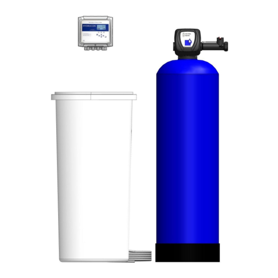
Page 19: Scope Of Supply
3. Scope of supply 3.1 Components Equipment Description ® VAS – CS 1,5 HYDRO ION (example) fig.3 1 = Resin vessel 1 (pressure tub) 2 = Control valve 3 = Brine tank 4 = Electronic control 5 = Input 6 = Output (softened water) 7 = Wash water drain Resin vessel Pressure tank of corrosion-resistant glass-fibre... -
Page 20: Resin
Resin media Strong acid cat-ion exchange resin to be suited for drinking water application PFC100E grade. Control valve Microprocessor controlled, menu driven system control operating modes, functions and display. Number: Operating pressure: 2,5 to 8 bar Operating temperature: 5 to 40 °C ®... -
Page 21: Micro Processor Control
Micro processor control Micro processor control in wall-mounted casing, menu driven for different operation modes such as: - volume control with temporally priority circuit - time control - quality control in combination with hardness control - forced regeneration - water refresh - automatic disinfection - external release - external regeneration... -
Page 22: Brine Tank
® VAS – CS 1,5 HYDRO ION Water meter as external installation unit, mounted direct to the soft water output. input 1 ½“ external thread Connection: output 1 ½“ internal thread Voltage: 12 V AC Cable suited to connect the control to the central control valve 1. -
Page 23: Chlorinator
Chlorinator (Option) Chlorinator used for the automatic disinfection during regeneration phase of softener, consisting of: - electrodes installed in PVC assembly element - control cable for the connection to the micro processor control Control cable Control voltage: max. 15 V 3/8“... -
Page 24: Accessories
3.2 Accessories Back flow prevention device To separate drinking water from non drinking water up to and including liquid category 4 (DIN 1988, part 4) for Connection size dependent on systems according to DIN 1717 with controlled customer’s request separation (installation type 2 according to DIN 1988) (Nom. -
Page 25: External Blending
1 1/2“ (AG) x 1 1/2“ (ÜM) Dimensions : Length: 1000 mm Regenerant Art.-No. In form of tablets (not granular!) 25 kg PE bag (Not available from Hydrotec UK Ltd.) Last change 10/2018 E-P | Subject to technical modifications 25/98... - Page 26 – Installation and assembly Index chapter Page General information Installation location Work prior to assembly Control of shipment Drain connection Incoming and soft water pipe Filling of filter vessel with quartz gravel and exchange resin Hydraulic connections at control valve ®...
- Page 27 25l bags. It is the responsibility of the commissioning engineer to fill the resin vessel with the gravel and resin. Hydrotec (UK) Ltd. will perform this service during commissioning visit. Necessary pipe connections to the central control valve must be performed on site.
- Page 28 Furthermore DIN 19636 (section: “protection against bacterial contamination”) must be observed: “As water softening systems, especially at discontinuous operation, are vulnerable to bacterial contamination, this must be prevented by means of suitable constructive or chemical-physical measures.” In order to keep that DIN 19636, a forced regeneration after 4 days (96 hours) has to be ®...
- Page 29 3.1 Filling of resin vessel with quartz gravel and exchange resin Assembly of resin vessel (pressure vessel) and brine tank, whereby a sufficient area must be available for operation and maintenance as well as supply and discharge lines. (Installation schematics see appendices 1) protection cap Seal the upper pipe opening of the riser with insulating tape in order to prevent resin or...
- Page 30 Filling of filter vessel as below: Step 1: Fill the resin vessel to approximately one quarter of its volume with clean water. Step 2: Fill the quartz gravel in the resin vessel. A good distribution must be guaranteed! Step 3: Separate the resin and fill it in the vessels.
- Page 31 4. Hydraulic connections at control valve Control valve 1“ - HYDRO ION ® VAS CS 1 Water meter 1 = Mains water connection (inlet) 2 = Soft water connection (outlet) 3 = Connection for brine line 4 = Waste water connection fig.18 Control valve 1 1/2“...
- Page 32 Brine line The brine is taken from the brine tank by means of a hose. Brine is drawn in by the control valve and flows through the intake pipe to the injector, passing the injector, before reaching the filter media. The injector is used to limit the brine quantity that is dependent on the quantity of filter media.
- Page 33 Important! All pipe connections must be done without any tension applied on. If necessary, the subsequent pipes must be provided with corresponding mounts or supports. Hoses must not be bent and hose connections must be screwed tight. Waste water, overflow and discharge lines must be provided from the connections at the control valve until waste water drain with an appropriate inclination.
- Page 34 ® VAS – CS 1 Connection water flow meter HYDRO ION The water meter is firmly installed in the soft water output of the valve in case of control valves 1” and is electrically connected to the pcb by means of plug cable (see figure 18).
- Page 35 – Micro processor control Index Chapter Page HC - SOFTENER Display / LED’s / Operating keys Display content whilst the controller is run up Main display – view Access levels Menu survey Alarm Acknowledge alarm Alarm records Total hardness Operation mode Protocol settings SD-Card (messaging) Language...
-
Page 36: Hc - Softener
1. HC – SOFTENER Our HC SOFTENER controllers ensure a regulation and control of operating process and regeneration of single unit. Regeneration can be released by different modes. Volume controlled with time priority (e.g. forced regeneration after 4 days). A hundred percent time controlled with a pre-set regeneration interval. Quality controlled regeneration, for example in conjunction with a hardness control device that supplies an external contact input in case of hardness break, is possible as well. -
Page 37: Display/Led's/ Operating Keys
1.1 Display/LED’s/ Operating keys LED error LED operation Function keys(charge acc. below display) Escape Input key/ Enter/CR Arrow keys 1.2 Display content whilst the controller is run up The controller is switched-on with the ON/OFF button (left side at casing) and supplied with mains voltage. -
Page 38: Main Display - View
1.3 Main display / view Two or three different main displays / views exist dependent on plant construction, in between the controller is switching automatically. Main display with date, time and software version Display for filter in operation – identical for all plant constructions - total capacity that can be treated - available residual capacity - actual flow... - Page 39 Regeneration display - actual regeneration phase - time remaining of regeneration phase LED green – OFF – Vessel in regeneration At the beginning of regeneration the following messages are shown on display. Pre-regeneration filter 1 Pre-operation filter 1 These messages are displayed on the screen until the control valve is in their correct end position. Last change 10/2018 E-P | Subject to technical modifications 39/98...
-
Page 40: Access Levels
Regeneration display – release of regeneration locked - brine formation time not yet finished/elapsed - lock time active 1.4 Access levels The controller has four access levels to avoid access by unauthorized persons. Example for input of password: Passwords There are 4 access levels with the below passwords: ... -
Page 41: Menu Survey
2. Menu survey The main menu is called via the keys F3 or Enter. Different functions and settings can be called from the main menu as below: Main menu Alarms Settings Total hardness Service Operation mode Protocol Setting SD-Card Language System Time System Date Information... -
Page 42: Alarm
3. Alarm 3.1 Acknowledge alarm Immediately upon release of an alarm, the below display is shown with the number of actual alarms and the reason for the record. The controller returns to main menu view via the keys F1 or Escape. The alarm record is maintained and can be called anew via the main menu. - Page 43 Example 2: Pre-warn „power failure“ “power failure“ warning is shown in the controller The warning record is shown even after the controller has been switched off and on again If power supply was interrupted for a longer time period, no flow was determined during such period and the capacity was not reduced ...
-
Page 44: Alarm Records
3.2 Alarm records Below is a survey of possible alarm or warning records: Record Failure Reason / background Action Pre-warn Maintenance Maintenance interval Arrange for maintenance soon and necessary soon running out confirm in menu Alarm Maintenance Maintenance interval ran Arrange for immediate maintenance necessary and confirm in menu... -
Page 45: Total Hardness
The below display is shown when calling the menu point „alarm“ in case of troublefree operation: LED red - OFF No record, warning and no alarm actually evident. 4. Total hardness The local mains water hardness is programmed in the menu point total hardness. Setting range 5°dH to 80°dH (89 ppm to 1430 ppm) 5. -
Page 46: Protocol Settings
6. Operation settings In the main menu item „Protocol settings“ the currently programmed protocol settings can be accessed via “Info Protocol”. For this purpose, no password is required. In the second menu item you can change the protocol settings. Access-Level 3 is required. Under the menu item „Single recording“, the following information will be stored on the SD card at the execution time. -
Page 47: Language
8. Language The unit for mains (permanent) hardness as well as the unit for resin capacity is altered in conjunction with the language setting. Unit total hardness in German: °dH Unit total hardness in English: Unit resin capacity in German: m³x°dH Unit resin capacity in English: m³... -
Page 48: Information
10. System update 11. Information All operation and regeneration parameters can be called in the information menu. Menu point Display Regeneration Total number of regenerations In case of Duplex or parallel system the sum of both vessels Regen. F1 Number of regenerations Vessel 1 Regen. -
Page 49: Menu Structure
12. Menu structure Alarms Settings Design Single / Double / Parallel Unit Rinsing Refresh mode Interval rinsing Interval Volume Flow Inputs Brine cure Ext. regeneration Brine alarm Pressure lack Brine tank 1 brine tank Regeneration mode Amount Time Chlor. gen. Chlor. - Page 50 Protocol settings Info Protocol SD Card Recording Delimiter Number. Of Elem. Rec. Intervall New.File Intervall Settings Protocol Recording Delimiter Rec. Intervall New.File-Interval Single recording SD card All Data > SD-Card PAR Data > SD-Card SYS Data > SD-Card PROC-Data > SD-Card SD- Card >...
-
Page 51: Electrical Installation / Wiring / Terminal Posts
13. Electrical installation / wiring / terminal posts Work at electric equipment Prior any work at electric equipment, the system/machine must be set de-energized. All respective regulations (DIN, VDE, UVV) must be observed for installation and operation of the controller. Repair work at electrical equipment must be carried out by skilled experts only! Electric equipment must be controlled in regular intervals! Any loose connections must be fixed! -
Page 52: Installation And Commissioning
13.1 Electrical installation / wiring / terminal posts Installation requirement The maximum admissible load of switching outputs as well as the total system capacity must not be exceeded by the connected consumer. All inductive consumers (valves, motors, contactors, transformers) must be equipped with suitable suppressors (RC-unit, varistor (VDR), diode etc.). -
Page 53: Technical Data Hc - Softener Controller
13.2 Technical Data HC – softener controller The controller must be operated in accordance with the below conditions: minimum typical maximum Unit Nom. operating voltage (AC) Mains frequency Nom. apparent power (excluding consumer) Ambient temperature (operation) °C Ambient temperature (storage) - 10 °C Rel. -
Page 54: Pcp Equipment And Terminal Charge
13.3 PCP equipment and terminal charge Main board and wiring Output 24 VDC for Input 24 VDC Output 24 VDC for Inputs and Outputs for the chlorine board clack board the clack board the control valves Power supply Relay outputs PE-terminal 1-6 Output for 230 V / 50 Hz... - Page 55 Wiring on the main board: Power supply No. Name Function Colour 230 V-PE Ground 230 V-N Power Supply 230 V / 50 Hz blue 230 V-L brown 230 V-PE 230 V-N Output 230 V / 50 Hz 230 V-L 230 V-PE PE-Connections 1-6.
- Page 56 Output Error – Warning – potential-free Colour Name Function selectable: Relay 5 warning, regeneration or brine error error Relay 6 The relays can be operated with the same voltage levels. Either 230 VAC, or 24 VAC or 24 VDC. Mixing of voltage levels is not allowed. Digital Inputs –...
- Page 57 Wiring clack board: Name Function Colour 10 Motor Enable Enabling piston motor green 11 Motor Direction Direction piston motor yellow 12 + 5 V Power supply white 13 GND brown Analogue output – optical detection of blue 14 Increments piston position 15 Increments Enable Enabling piston control 16 water meter pulses...
- Page 58 Board at the control valve Name Function Colour 29 38 Motor Enable Enabling piston motor purple 28 37 Motor Direction Direction piston motor grey 27 36 + 5 V Power supply black 26 35 GND Analogue output – optical Increments blue 25 34 detection of piston position...
- Page 59 Wiring chlorinator board: No. Name Function Colour brown 01/ 0 V power supply chlorinator blue 02 / 0 V 24 V power supply chlorinator board power supply chlorinator board blue 24 V power supply chlorinator board (red) power supply chlorinator board (blue) The power supply of the chlorinator(s) is provided in opposite polarity after each treatment.
-
Page 60: Fine Fuses
Board in the housing cap Connection for USB for PC SD memory card connection 13.4 Fine fuses Name Type 5 x 20 mm fuse T 200mA L 250V 5 x 20 mm fuse T 5A L 250V Last change 10/2018 E-P | Subject to technical modifications 60/98... -
Page 61: Vas - Cs
® VAS – CS Parameter settings HYDROION Regeneration cycles and times 25 - 50 - 75 - 125 - 150 - 200 - 250 - 375 - 600 - ® Type HYDROION 2" 2" 2" Connections 1" 1" 1" 1 1/2" 1 1/2"... - Page 62 – Commissioning / Taking out of Service Index chapter Page Check prior to commissioning Start up of softener Preparation Programming of control unit Backwash of softener / manual regeneration Brine tank filling Adjusting of soft water hardness ® Blending at control valve HYDRO ION VAS - CS 1 Control of soft water hardness Taking out of operation...
-
Page 63: Check Prior To Commissioning
1. Check prior to commissioning Filling of quartz gravel / resin Have the resin vessels (pressure vessel) been filled as described in chapter Quantity see table chapter / point 2 Hydraulic connections Is the below pipeline connected and tight? - mains water pipe - soft water pipe - wash water pipe (waste water) - brine line... -
Page 64: Start Up Of Softener
2. Start- up of softener Commissioning and start-up may be carried out by skilled experts only. We recommend that such work is done by our service personnel. This will be performed by the Hydrotec engineer upon the completion of a Commissioning Request Form. Preparation Close stop valves before and after softener. -
Page 65: Backwash Of Softener / Manual Regeneration
Fill the salt tank and distribute even on the sieve base (common salt tablets are required for regeneration; that is not supplied by Hydrotec (UK) Ltd. The brine tank can be filled to approx. 150 to 200 mm to lid. -
Page 66: Adjusting Of Soft Water Hardness
Stop valves The valves must be opened in mains water pipe and in soft water pipe so that water can be removed. Setting of soft water The blending water hardness is set to 60 ppm at the blending unit of the control valve 1“and at an installed hardness mounting unit (for 1“... -
Page 67: Taking Out Of Operation
Volume reduction Dependent on application, a volume reduction of the system may be necessary in order to avoid excess operation (the residual hardness can increase when the maximum flow is exceeded). Such volume reduction must be carried out at soft water side or by the installation of a volume limit unit. - Page 68 – Troubleshooting / fault finding Index chapter Page Malfunction control unit No water supplied by softener Residual hardness at consumer too high Overflow of brine tank Other faults Last change 10/2018 E-P | Subject to technical modifications 68/98...
- Page 69 1. Malfunction of micro processor control Different modes are monitored during operation and regeneration of the softener. If during operation of the central control valve faults should become evident, the failure records are shown in the LCD display and the failure contact and failure signal light switched. Information regarding possible failure records see chapter / point 6.
- Page 70 3. Excess residual hardness If an assembly mount including blending valve is installed, that must initially be controlled and adjusted. No. Inspection Result Action Open soft water sample valve and Residual hardness < 5.0 Proceed with 6 control residual hardness (CaCO Residual hardness >...
- Page 71 4. Brine tank overflows No. Inspection Result Action Is the power supply as far as the Power supply is Proceed with 2 control system ensured without guaranteed interruption? Power supply is Provide power supply interrupted and initiate regeneration Check whether or not the control Operational readiness Proceed with 3 valve is ready for operation...
- Page 72 5. Additional failures No. Failure Possible reason Action Resin in channel a) missing or broken top a) dismantle or replace top nozzle nozzle b) air included in softener b) guarantee that an air stop is available in brine tank c) not adjusted backwash c) check backwash flow stop (DLFC)
- Page 73 – Monitoring and Maintenance VIII Index chapter Page General information Control to be carried out by operator (inspection) Check permanent hardness mains water Check soft water hardness Check setting of control Check salt level in brine tank Check brine level Check contamination in brine tank Check tightness / visual inspection Maintenance...
-
Page 74: General Information
A plant inspection shall be carried out after 2 months at the latest. Such inspection is possible by the operator or an authorized service company. A semi-annual maintenance of the system shall be carried out by Hydrotec UK Ltd. (service) or an authorized expert. -
Page 75: Check Permanent Hardness Mains Water
Check permanent hardness mains Hardness control is carried out by means of test kits. water If the mains water total hardness changes, calculate and adjust the soft water quantity again according to appendices 2 and 3. Setting of mains water hardness is according to chapter / point 4. -
Page 76: Check Brine Level
Check brine level The filling height of the regeneration salt should always be above the liquid level of the brine. Otherwise correct operation of the regeneration cycle is impossible with the result of hardness break. Check contamination of brine tank Interval: after 2 months Tightness check;... -
Page 77: Cleaning
3.1 Cleaning Important! Please bear in mind that the cleaning should either be carried out by Hydrotec (UK) Ltd or by an authorized specialist company. Injector and injector sieve must be dismounted and cleaned in regular intervals dependent on purity of mains water (during plant maintenance at the latest). -
Page 78: Contact Address Service
® Control valve HYDRO ION - CS 1.5 ® Control valve HYDRO ION - CS 2 Brine draw in Flow control Flow (BLFC) direction fig.25 Injector In order to carry out cleaning and maintenance work at the softener, it must be disconnected from the mains water and depressurised. - Page 79 Only use components which are approved for this valve type. All inspection, cleaning and maintenance work shall be carried out with corresponding care and disinfection measures be taken on request. Please bear in mind that the annual maintenance should either be carried out by Hydrotec (UK) Ltd or by an authorised specialist company since otherwise we cannot accept any warranty claim.
- Page 80 Appendices 1: Installation schematic softener Last change 10/2018 E-P | Subject to technical modifications 80/98...
- Page 81 Appendices 2: Calculation soft water capacity Capacity of softener x S in m³ soft water Local permanent hardness L = soft water volume between two regenerations S = Safety factor 0.9 for boiler water and RO 0.8 for strong fluctuating supply water hardness The local permanent water hardness shall be determined and controlled by means of a test kit.
- Page 82 Appendices 3: Calculation sodium contents: The sodium concentration in mixed water is increased due to softening dependent on the incoming water hardness and the set mixed water hardness. According to drinking water regulation 2001, the limit value for sodium is 200 mg/L. If the mixed water or the sodium contents is still in accordance with the regulation can be calculated as below: ppm (CaCO...
- Page 83 Start up and training record ® Softener HYDRO ION Plant size / Serial number: ________________________________________________ Customer: ________________________________________________ Temperature incoming water:____________________ °C Filter supply pressure: ____________________ (flow conditions) Filter initial pressure: ____________________ (flow conditions) Hardness incoming water: ____________________ ppm (CaCO ...
- Page 84 Parameters Actual value Component Type of softener Injector number (or colour) Size of DLFC Size of BLFC Sieve base (yes – no) Height of brine tank (mm) (to be measured) Diameter of brine tank (mm) (to be measured) Height of brine tank (mm) (to be measured) Setting of control Designation...
- Page 85 ® Log Book Softener HYDRO ION Installation site: _____________________________________________________ Time period: ________________________________________________________ Date Total Total Operating Temperature Water Salt Signed hardness hardness pressure (input) metre storage incoming soft water (input) (°C) count (m³) (kg) water (ppm CaCO (bar) (ppm CaCO Last change 10/2018 E-P | Subject to technical modifications 85/98...
- Page 86 ® Log Book Softener HYDRO ION Installation site: _____________________________________________________ Time period: ________________________________________________________ Date Total Total Operating Temperature Water Salt Signed hardness hardness pressure (input) metre storage incoming soft water (input) (°C) count (m³) (kg) water (ppm CaCO (bar) (ppm CaCO Last change 10/2018 E-P | Subject to technical modifications 86/98...
-
Page 98: Last Change 10/2018 E-P | Subject To Technical Modifications
Herausgeber/Publisher: HYDROTEC® prepared by: AL / AC All rights reserved! © 10/2018 by HYDROTEC 17.10.2018 – modification: Chapter V – point 14 Float height adjustment due to a new brine valve 3/4" Water softeners: VAS 250/375/600-CS A / B Subject to technical modification! All design parameters and dimensions as well as pictures correspond to the actual state at the date the documentation was prepared.
Need help?
Do you have a question about the HYDROION VAS-CS Series and is the answer not in the manual?
Questions and answers