Table of Contents
Advertisement
Quick Links
Advertisement
Chapters
Table of Contents
Troubleshooting

Related Manuals for Dinli DL-702 2008


Summary of Contents for Dinli DL-702 2008
- Page 1 FOREWORD/INDEX 【0-0】...
- Page 2 FOREWORD/INDEX DINLI 700 cc Service Manual All rights reserved. No parts of this publication may be reproduced, stored in a retrieval system, or transmitted in any form or by any means, electronic mechanical photocopying, recording or otherwise, without the prior written permission of Dinli Metal Industrial Co., Ltd.. No liability can be accepted for any inaccuracies or omissions in this publication, although every possible care has been taken to make it as complete and accurate as possible. The right is reserved to make changes at any time without prior notice and without incurring an ...
- Page 3 For the duration of the warranty period, we recommend that all repairs and scheduled maintenance be performed in accordance with this service manual. Any owner maintenance or repair procedure not performed in accordance with this manual may void the warranty. To get the longest life out of your vehicle: ● Follow the Periodic Maintenance Chart in the Service Manual. ● Be alert for problems and non‐scheduled maintenance. ● Use proper tools and genuine DINLI vehicle parts. Genuine parts provided as spare parts are listed in the Parts Catalog. ● Follow the procedures in this manual carefully. Don’t take shortcuts. ● Remember to keep complete records of maintenance and repair with dates and any replaced parts. How to Use This Manual ...
- Page 4 FOREWORD/INDEX Whenever you see these WARNING and CAUTION symbols, heed their instructions! Always follow safe operating and maintenance practices. WARNING This warning symbol identifies special instructions or procedures, which if not correctly followed, could result in personal injury, or loss of life. CAUTION This caution symbol identifies special instructions or procedures, which if not strictly observed, could result in damage to or destruction of equipment. This manual contains four more symbols (in addition to WARNING and CAUTION), which will help you distinguish different types of information. NOTE ○ This note symbol indicates points of particular interest for more efficient and convenient operation. ● Indicates a procedural step or work to be done. ○ Indicates a procedural sub‐step or how to do the work of the procedural step it follows. It also precedes the text of a NOTE. Indicates a conditional step or what action to take based on the results of the test or inspection in the procedural step or sub‐step it follows. ...
- Page 5 FOREWORD/INDEX CHAPTER INDEX CHAPTER 1 GENERAL INFORMATION CHAPTER 2 WHEELS/TIRES CHAPTER 3 BRAKE CHAPTER 4 SUSPENSION/STEERING /DRIVE SHAFT CHAPTER 5 BODY CHAPTER 6 ENGINE CHAPTER 7 COOLING AND LUBRICATION SYSTEM CHAPTER 8 ELECTRICAL SYSTEM CHAPTER 9 PERIODIC MAINTENANCE CHAPTER 10 APPENDIX 【0-4】...
-
Page 6: Table Of Contents
GENERAL INFORMATION GENERAL INFORMATION Table of Contents Before Servicing‐‐‐‐‐‐‐‐‐‐‐‐‐‐‐‐‐‐‐‐‐‐‐‐‐‐‐‐‐-‐‐‐‐‐‐‐‐‐‐‐‐‐‐‐‐‐‐‐‐‐‐‐‐‐‐‐‐‐‐--‐‐‐‐‐‐‐‐‐‐‐‐‐‐‐‐‐‐‐‐‐‐‐‐‐‐‐‐‐‐‐‐1‐2 General Precautions‐‐‐‐‐‐‐‐‐‐‐‐‐‐‐‐‐‐‐‐‐‐‐‐‐‐‐‐‐‐‐‐‐‐‐‐‐‐‐‐‐‐‐‐‐‐‐‐‐‐‐‐‐‐‐‐‐-‐‐‐‐‐‐‐‐‐‐‐‐‐‐‐‐‐‐‐‐‐‐‐‐‐‐‐‐‐‐‐1‐5 DINLI DL‐702‐‐‐‐‐‐‐‐‐‐‐‐‐‐‐‐‐‐‐‐‐‐‐‐‐‐‐‐‐‐‐‐‐‐‐‐‐‐‐‐‐‐‐‐‐‐‐‐‐‐‐‐‐‐‐‐‐‐‐‐‐‐‐‐‐‐‐‐‐‐‐‐‐‐‐‐‐‐‐‐‐‐‐‐‐‐‐‐‐‐‐‐‐‐‐‐‐1‐6 Model Identifications‐‐‐‐‐‐‐‐‐‐‐‐‐‐‐‐‐‐‐‐‐‐‐‐‐‐‐‐‐‐‐‐‐‐‐‐‐‐‐‐‐‐‐‐‐‐‐‐‐‐‐‐‐‐‐‐‐‐‐‐‐‐‐‐‐‐‐‐‐‐‐‐‐‐‐‐‐‐‐‐‐‐‐‐‐‐‐ 1‐7 Fuel, Oil and Engine Coolant Recommendation‐‐‐‐‐‐‐‐‐‐‐‐‐‐‐‐‐‐‐‐‐‐‐‐‐‐‐‐‐‐‐‐‐‐‐‐‐‐‐‐‐‐‐‐‐‐‐‐‐‐‐‐‐1‐8 Fuel (For USA and Canada) ‐‐‐‐‐‐‐‐‐‐‐‐‐‐‐‐‐‐‐‐‐‐‐‐‐‐‐‐‐‐‐‐‐‐‐‐‐‐‐‐‐‐‐‐‐‐‐‐‐‐‐‐‐‐‐‐‐‐‐‐‐‐‐‐‐‐‐‐‐‐‐‐‐1‐8 Fuel (For Other Countries) ‐‐‐‐‐‐‐‐‐‐‐‐‐‐‐‐‐‐‐‐‐‐‐‐‐‐‐‐‐‐‐‐‐‐‐‐‐‐‐‐‐‐‐‐‐‐‐‐‐‐‐‐‐‐‐‐‐‐‐‐‐‐‐‐‐‐‐‐‐‐‐‐‐‐1‐8 Engine Oil (For USA) ‐‐‐‐‐‐‐‐‐‐‐‐‐‐‐‐‐‐‐‐‐‐‐‐‐‐‐‐‐‐‐‐‐‐‐‐‐‐‐‐‐‐‐‐‐‐‐‐‐‐‐‐‐‐‐‐‐‐‐‐‐‐‐‐‐‐‐‐‐‐‐‐‐‐‐‐‐‐‐‐‐1‐8 Engine Oil (For Other Countries) ‐‐‐‐‐‐‐‐‐‐‐‐‐‐‐‐‐‐‐‐‐‐‐‐‐‐‐‐‐‐‐‐‐‐‐‐‐‐‐‐‐‐‐‐-‐‐‐‐‐‐‐‐‐‐‐‐‐‐‐‐‐‐‐‐‐1‐8 Front Differential Gear Oil‐‐‐‐‐‐‐‐‐‐‐‐‐‐‐‐‐‐‐‐‐‐‐‐‐‐‐‐‐‐‐‐‐‐‐‐‐‐‐‐‐‐‐‐‐‐‐‐‐‐‐‐‐‐‐‐‐‐‐‐‐‐‐‐‐‐‐‐‐‐‐‐‐‐‐1‐8 Rear Gear (Final) Box Oil‐‐‐‐‐‐‐‐‐‐‐‐‐-‐‐‐‐‐‐‐‐‐‐‐‐‐‐‐‐‐‐‐‐‐‐‐‐‐‐‐‐‐‐‐‐‐‐‐-‐‐‐‐‐‐‐‐‐‐‐‐‐‐‐‐‐‐‐‐‐‐‐‐‐‐‐1‐8 ... -
Page 7: Before Servicing
GENERAL INFORMATION Before Servicing Before starting to perform an inspection service or carry out a disassembly and reassembly operation on a quad, read the precautions given below. To facilitate actual operations, notes, illustrations, photographs, cautions, and detailed descriptions have been included in each chapter wherever necessary. This section explains the items that require particular attention during the removal and reinstallation or disassembly and reassembly of general parts. Especially note the following: (1) Dirt Before removal and disassembly, clean the quad. Any dirt entering the engine will shorten the life of the ... - Page 8 GENERAL INFORMATION (6) Force Common sense should dictate how much force is necessary in assembly and disassembly. If a part seems especially difficult to remove or install, stop and examine what may be causing the problem. Whenever tapping is necessary, tap lightly using a wooden or plastic‐faced mallet. Use an impact driver for screws (particularly for the removing screws held by non‐permanent locking agent) in order to avoid damaging the screw heads. ...
- Page 9 GENERAL INFORMATION When installing cir‐clips and retaining rings, take care to compress or expand them only enough to install them and no more. Install the cir‐clip with its chamfered side facing load side as well. Replace any cir‐clips, retaining rings, and cotter pins with new ones, as removal weakens and deforms them, they could become detached while the quad is driven, leading to a major problem. (15) Lubrication Engine wear is generally at its maximum while the engine is warming up and before all the sliding surfaces ...
-
Page 10: General Precautions
GENERAL INFORMATION General Precautions WARNING ○ Proper service and repair procedures are important for the safety of the service mechanic and the safety and reliability of the vehicle. ○ When 2 or more persons work together, pay attention to the safety of each other. ○ When it is necessary to run the engine indoors, make sure that exhaust gas is forced outdoors. ○ When working with toxic or flammable materials, make sure that the area you work in is well‐ventilated and that you follow all of the material manufacturer’s instructions. ○ Never use gasoline as a cleaning solvent. ○ To avoid getting burned, do not touch the engine, engine oil, radiator and exhaust system until they have cooled. ○ After servicing the fuel, oil, water, exhaust or brake systems, check all lines and fittings related to the ... -
Page 11: Dinli
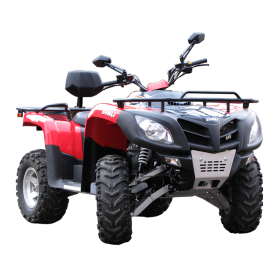
GENERAL INFORMATION DINLI DL‐702 Right Side Left Side ● Difference between photograph and actual vehicle may exist depending on the markets. ... -
Page 12: Model Identifications
GENERAL INFORMATION Model Identification Engine serial number Vehicle identification number ENGINE SERIAL NUMBER (Ex. 15M18XXXXX) VEHICLE IDENTIFICATION (ex. RFWAK85CX6Txxxxxx) Whenever corresponding with DINLI about a particular issue, the engine number and serial number are important for vehicle identification. 【1-7】... -
Page 13: Fuel, Oil And Engine Coolant Recommendation
GENERAL INFORMATION Fuel, Oil and Engine Coolant Recommendation Fuel (For USA and Canada) ● Use only unleaded gasoline of at least 87 pump octane (R/2 + M/2) or 95 octane or higher rated by the Research Method. ● Gasoline containing MTBE (Methyl Tertiary Butyl Ether), less than 10% ethanol, or less than 5 % methanol with appropriate cosolvents and corrosion inhibitor is permissible. Fuel (For Other Countries) ● Gasoline used should be graded 95 octane (Research Method) or higher. An unleaded gasoline is recommended. Engine Oil (For USA) ● Dinli recommends the oil which is rated SF or SG under the API(American Petroleum Institute) service classification. The recommended viscosity is SAE 10W‐40. If SAE 10W‐40 oil is not available, select an alternative according to the following chart. Engine Oil (For Other Countries) ● Use a premium quality 4‐stroke motor oil to ensure longer service life of your vehicle. Use only oil which are rated SF or SG under the API service classification. The recommended viscosity is SAE 10W‐40. If SAE 10W‐40 motor oil is not available, select an alternative according to the right chart. Front Differential Gear Oil ● Use hypoid gear oil that meets the API service classification GL‐5 and is rated SAE #80W‐90. Rear Gear (Final) Box Oil ● Use hypoid gear oil that meets the API service classification GL‐5 and is rated SAE #80W‐90. ... -
Page 14: Brake Fluid
● Use an anti‐freeze/engine coolant compatible with an aluminum radiator, mixed with distilled water only. Water For Mixing ● Use distilled water only. Water other than distilled water can corrode and clog the aluminum radiator. Anti‐Freeze/Engine Coolant ● The engine coolant performs as a corrosion and rust inhibitor as well as anti‐freeze. Therefore, the engine coolant should be used at all times even though the atmospheric temperature in your area does not go down to freezing point. ● Dinli recommends the use of engine coolant is compatible with an aluminum radiator. Liquid Amount of Water/Engine Coolant Solution capacity (total): Approx. 1950 ml ● For engine coolant mixture information, refer to cooling system section in page 7‐2. CAUTION Mixing of anti‐freeze/engine coolant should be limited to 70%. Mixing beyond it would reduce its efficiency. If the anti‐freeze/engine coolant mixing ratio is below 50%, rust inhabiting performance is ... -
Page 15: Break-In Procedures
GENERAL INFORMATION Break‐In Procedures ● During manufacture only the best possible materials are used and all machined parts are finished to a very high standard but it is still necessary to allow the moving parts to “Break‐In” before subjecting the engine to maximum stresses. The future performance and reliability of the engine depends on the care and restraint exercised during its early life. The general rules are as follows. ○ Keep to these break‐in engine speed limits: Break‐in engine speeds Initial 500 km: Less than 1/2 throttle ○ Upon reaching as odometer reading of 500 km you can subject the vehicle to full throttle operation, for short periods of time. ... -
Page 16: Information Labels
GENERAL INFORMATION Information Labels Always stop the vehicle completely before changing Do not consume alcohol, from forward to reverse or drugs or cigarettes before or vice versa. -
Page 17: General Specifications
GENERAL INFORMATION General Specification NOTE: Specifications subject to change without notice. ENGINE Model DL‐702 Engine 4 –stroke, DOHC Number of cylinders 1 Bore and stroke 102 mm × 85 mm Compression ratio 10.0:1 Displacement 694.6 cc Air cleaner Foam Coolant system Liquid cooled Cooling device operating temperature 85℃ 1:2 water/anti‐freeze [ethylene glycol (containing corrosion Coolant inhibitors for aluminum engines and radiators)]. Starter system Electrical and recoil starter Carburetor Mikuni BSR42 Idle speed 1300 ± 100 rpm Lubrication system Force pressure and wet sump 4 –cycle motorcycle engine oil SAE 10W‐40, grade API SF or Lubricant ... - Page 18 GENERAL INFORMATION CHASSIS Frame Steel Overall length 2200 mm Overall width 1230 mm Overall height 1230 mm Seat height 916 mm Wheel base 1305 mm Ground clearance, unloaded 295 mm Water crossing maximum depth 520 mm Dry weight Approx. 298 kg Loading limit (Incl. rider, cargo, etc…) 250 kg Front track 952 mm Rear track 982 mm ...
- Page 19 GENERAL INFORMATION Front tire AT 25 × 8 – 12, tubeless Rear tire AT 25 × 10 – 12, tubeless Recommended coil tire pressure (Front/Rear) 35 kPa/ 35 kPa (5.0 psi/ 5.0 psi) ELECTRICAL Ignition type CDI Ignition timing 7 ° B.T.D.C at 1300 rpm Spark plug NGK CR6E Spark plug gap 0.7 – 0.8 mm Alternator type Three‐phase AC Alternator output DC 14V‐23A @ 3000 rpm Battery GS, GTX20L‐BS, 12 V/20Ah Main fuse 30 A Fuse ...
- Page 20 WHEELS/TIRES WHEELS/TIRES Table of Contents Specifications‐‐‐‐‐‐‐‐‐‐‐-‐‐‐‐‐‐‐‐‐‐‐‐‐‐‐‐‐‐‐‐‐‐‐‐‐‐‐‐‐‐‐‐‐‐‐‐‐‐‐‐‐‐‐‐‐‐‐‐‐‐‐‐‐‐‐‐‐‐‐‐‐‐‐‐‐‐‐‐‐‐‐‐‐‐‐‐‐‐‐‐‐‐‐2‐2 Construction‐‐‐‐‐‐‐‐‐‐‐‐‐‐‐‐‐‐‐‐‐‐‐‐‐‐‐‐‐‐‐‐‐‐‐‐‐‐‐‐‐‐‐‐‐‐‐‐‐‐‐‐‐‐‐‐‐‐‐‐‐‐‐‐‐‐‐‐‐‐‐‐‐‐‐‐‐‐‐‐‐‐‐‐‐‐‐‐‐‐‐‐‐‐‐‐2‐3 Wheel (Rim) ‐‐‐‐‐‐‐‐‐‐‐‐‐‐‐‐‐‐‐‐‐‐‐‐‐‐‐‐‐‐‐‐‐‐‐‐‐‐‐‐‐‐‐‐‐‐‐‐‐‐‐‐‐‐‐‐‐‐‐‐‐‐‐‐‐‐‐‐‐‐‐‐‐‐‐‐‐‐‐‐‐‐‐‐‐‐‐‐‐‐‐‐‐‐‐‐2‐4 Removal‐‐‐‐‐‐‐‐‐‐‐‐‐‐‐‐‐‐‐‐‐‐‐‐‐‐‐‐‐‐‐‐‐‐‐‐‐‐‐‐‐‐‐‐‐‐‐‐‐‐‐‐‐‐‐‐‐‐‐‐‐‐‐‐‐‐‐‐‐‐‐‐‐‐‐‐‐‐‐‐‐‐‐‐‐‐‐‐‐‐‐‐‐‐‐‐‐2‐4 Installation‐‐‐‐‐‐‐‐‐‐‐‐‐‐‐‐‐‐‐‐‐‐‐‐‐‐‐‐‐‐‐‐‐‐‐‐‐‐‐‐‐‐‐‐‐‐‐‐‐‐‐‐‐‐‐‐‐‐‐‐‐‐‐‐‐‐‐‐‐‐‐‐‐‐‐‐‐‐‐‐‐‐‐‐‐‐‐‐‐‐‐‐‐‐2‐4 Inspection‐‐‐‐‐‐‐‐‐‐‐‐‐‐‐‐‐‐‐‐‐‐‐‐‐‐‐‐‐‐‐‐‐‐‐‐‐‐‐‐‐‐‐‐‐‐‐‐‐‐‐‐‐‐‐‐‐‐‐‐‐‐‐‐‐‐‐‐‐‐‐‐‐‐‐‐‐‐‐‐‐‐‐‐‐‐‐‐‐‐‐‐‐‐‐2‐5 Replacement‐‐‐‐‐‐‐‐‐‐‐‐‐‐‐‐‐‐‐‐‐‐‐‐‐‐‐‐‐‐‐‐‐‐‐‐‐‐‐‐‐‐‐‐‐‐‐‐‐‐‐‐‐‐‐‐‐‐‐‐‐‐‐‐‐‐‐‐‐‐‐‐‐‐‐‐‐‐‐‐‐‐‐‐‐‐‐‐‐‐‐‐2‐5 Tire‐‐‐‐‐‐‐‐‐‐‐‐‐‐‐‐‐‐‐‐‐‐‐‐‐‐‐‐‐‐‐‐‐‐‐‐‐‐‐‐‐‐‐‐‐‐‐‐‐‐‐‐‐‐‐‐‐‐‐‐‐‐‐‐‐‐‐‐‐‐‐‐‐‐‐‐‐‐‐‐‐‐‐‐‐‐‐‐‐‐‐‐‐‐‐‐‐‐‐‐‐‐‐‐‐‐‐‐2‐6 Removal‐‐‐‐‐‐‐‐‐‐‐‐‐‐‐‐‐‐‐‐‐‐‐‐‐‐‐‐‐‐‐‐‐‐‐‐‐‐‐‐‐‐‐‐‐‐‐‐‐‐‐‐‐‐‐‐‐‐‐‐‐‐‐‐‐‐‐‐‐‐‐‐‐‐‐‐‐‐‐‐‐‐‐‐‐‐‐‐‐‐‐‐‐‐‐‐2‐6 Installation‐‐‐‐‐‐‐‐‐‐‐‐‐‐‐‐‐‐‐‐‐‐‐‐‐‐‐‐‐‐‐‐‐‐‐‐‐‐‐‐‐‐‐‐‐‐‐‐‐‐‐‐‐‐‐‐‐‐‐‐‐‐‐‐‐‐‐‐‐‐‐‐‐‐‐‐‐‐‐‐‐‐‐‐‐‐‐‐‐‐‐‐2‐6 Inspection‐‐‐‐‐‐‐‐‐‐‐‐‐‐‐‐‐‐‐‐‐‐‐‐‐‐‐‐‐‐‐‐‐‐‐‐‐‐‐‐‐‐‐‐‐‐‐‐‐‐‐‐‐‐‐‐‐‐‐‐‐‐‐‐‐‐‐‐‐‐‐‐‐‐‐‐‐‐‐‐‐‐‐‐‐‐‐‐‐‐‐‐‐2‐8 Hub‐‐‐‐‐‐‐‐‐‐‐‐‐‐‐‐‐‐‐‐‐‐‐‐‐‐‐‐‐‐‐‐‐‐‐‐‐‐‐‐‐‐‐‐‐‐‐‐‐‐‐‐‐‐‐‐‐‐‐‐‐‐‐‐‐‐‐‐‐‐‐‐‐‐‐‐‐‐‐‐‐‐‐‐‐‐‐‐‐‐‐‐‐‐‐‐‐‐‐‐‐‐‐‐‐‐‐2‐9 Front Hub Removal‐‐‐‐‐‐‐‐‐‐‐‐‐‐‐‐‐‐‐‐‐‐‐‐‐‐‐‐‐‐‐‐‐‐‐‐‐‐‐‐‐‐‐‐‐‐‐‐‐‐‐‐‐‐‐‐‐‐‐‐‐‐‐‐‐‐‐‐‐‐‐‐‐‐‐‐‐‐‐‐‐2‐9 Front Hub Inspection‐‐‐‐‐‐‐‐‐‐‐‐‐‐‐‐‐‐‐‐‐‐‐‐‐‐‐‐‐‐‐‐‐‐‐‐‐‐‐‐‐‐‐‐‐‐‐‐‐‐‐‐‐‐‐‐‐‐‐‐‐‐‐‐‐‐‐‐‐‐‐‐‐‐‐‐‐‐‐2‐9 Front Hub Installation‐‐‐‐‐‐‐‐‐‐‐‐‐‐‐‐‐‐‐‐‐‐‐‐‐‐‐‐‐‐‐‐‐‐‐‐‐‐‐‐‐‐‐‐‐‐‐‐‐‐‐‐‐‐‐‐‐‐‐‐‐‐‐‐‐‐‐‐‐‐‐‐‐‐‐‐2‐10 Rear Hub Removal‐‐‐‐‐‐‐‐‐‐‐‐‐‐‐‐‐‐‐‐‐‐‐‐‐‐‐‐‐‐‐‐‐‐‐‐‐‐‐‐‐‐‐‐‐‐‐‐‐‐‐‐‐‐‐‐‐‐‐‐‐‐‐‐‐‐‐‐‐‐‐‐‐‐‐‐‐‐‐‐2‐10 Rear Hub Inspection‐‐‐‐‐‐‐‐‐‐‐‐‐‐‐‐‐‐‐‐‐‐‐‐‐‐‐‐‐‐‐‐‐‐‐‐‐‐‐‐‐‐‐‐‐‐‐‐‐‐‐‐‐‐‐‐‐‐‐‐‐‐‐‐‐‐‐‐‐‐‐‐‐‐‐‐‐‐2‐10 Rear ...
-
Page 21: Specifications
WHEELS/TIRES Specifications Item ... -
Page 22: Construction
WHEELS/TIRES Construction 1 Front Disk 6 Nut (16pcs) 11 Tire 2 Front Wheel Hub 7 Castle Nut (4pcs) 12 Rim 3 Rear Wheel Hub 8 ... -
Page 23: Wheel (Rim)
WHEELS/TIRES Wheel (Rim) Removal ● Loosen the wheel nuts [A] for just one turn. ● Support the vehicle on a stand or the jack so that the wheels are off the ground. ● Take off the wheel nuts and remove the wheel. Installation ● Check the tire rotation mark [A] on the tire, and install the wheel accordingly. NOTE ○ The direction of the tire rotation is shown by an arrow on the tire sidewall. ● Position the wheel so that the air valve [B] is toward the outside of the vehicle. ● Tighten the wheel nuts to the specified torque in a criss‐cross pattern. Tightening Torque: 60 N‐m (6.0 kgf‐m, 43.5 lb‐ft) 【2-4】... -
Page 24: Inspection
WHEELS/TIRES Inspection ● Examine both sides of the rim for dents [A]. If the rim is dented, replace it. ● If the tire is removed, inspect the air sealing surfaces [A] of the rim for scratches or nicks. Smooth the sealing surfaces with fine emery cloth if necessary Replacement ● Remove the wheel (see Wheel Removal) ● Disassemble the tire from the rim (see Tire Removal). ○ Remove the air valve and discard it. CAUTION Replace the air valve whenever the tire is replaced. Do not reuse the air valve. -
Page 25: Tire
WHEELS/TIRES Tire Removal ● Remove the wheel. ● Unscrew the valve core [A] to deflate the tire. ● Dismount the bead from the rim completely as shown. Tire Bead Breaker WARNING When dismounting the bead from the rim, it is necessary to deflate the tire to prevent burst. ● Separate the tire from the rim using a tire bead breaker and rim protector. CAUTION When using the tire bead breaker, do not scratch or hit the sealing portion (hump) of the wheel or it may cause air leakage. Installation ● Inspect the rim (see Wheel (Rim) Inspection). ... - Page 26 WHEELS/TIRES ● Lubricate the tire beads and rim flanges with a soap and water. WARNING Do not use the lubricant other than a water and soap solution, or water to lubricate the tire beads and rim because it may cause tire separation. ● Check the tire rotation mark [A] on the tire, and install the tire on the rim accordingly. ○ The tires should be installed on the rims so that each air valve is toward outside of the vehicle. NOTE ○ The direction of the tire rotation is shown by an arrow on the tire sidewall. ● Lubricate the tire beads again and center the tire on the rim. ● Mount the tire on the rim by using the tire changer. ● Inflate the tire until the tire beads seat on the rim. ...
-
Page 27: Inspection
WHEELS/TIRES ● Check the tire pressure using an air pressure gauge. Tire Air Pressure (when cold) Front: 35 kPa (5.0 psi) Rear: 35 kPa (5.0 psi) ● Install the wheel (see Wheel Installation). ● Wipe off the soap and water solution on the tire and dry the tire before operation. Tire Inspection ... -
Page 28: Hub
WHEELS/TIRES Hub Front Hub Removal ● Remove the wheel (see Wheel Removal). ● Remove the cotter pin. CAUTION Replace the removed cotter pin with a new one. ● Remove the caliper by taking off the mounting bolts [A], and let the caliper hang free. ● Remove the axle nut and pull off the front hub with brake disc. ● Separate the brake disc by removing the brake disc mounting bolts [B]. Front Hub Inspection ● Inspect the front hub bolts [A] for wear or damage. If any damages are found, replace the damaged bolts with new ones. ... -
Page 29: Front Hub Installation
WHEELS/TIRES Front Hub Installation ● Install the front hub in the reverse order of removal. Pay attention to the following points. ○ Tighten the brake disc mounting bolts [A] to the specified torque. Tightening Torque: 25 N‐m (2.5 kgf‐m, 18.0 lb‐ft) ○ Apply GREASE to the hub spline. ○ Tighten the axle nut to the specified torque. Tightening Torque: 110 N‐m (11.0 kgf‐m, 79.5 lb‐ft) ○ Insert the new cotter pin and bent it over the nut. Rear Hub Removal ● Remove the wheel (See wheel Removal) ● Remove the cotter pin [1]. CAUTION Replace the removed cotter pin with a new one. ● Remove the axle nut [2] with washer and pull off the rear hub. Rear Hub Inspection ● Inspect the rear hub bolts [A] for wear or damage. If any damages are found, replace the damaged bolts with new ones. ... -
Page 30: Rear Hub Installation
WHEELS/TIRES Rear Hub Installation ● Install the rear hub in the reverse order of removal. Pay attention to the following points. ○ Apply GREASE to the hub spline. ○ Tighten the axle nut [1] to the specified torque. Tightening Torque: 110 N‐m (11.0 kgf‐m, 79.5 lb‐ft) ○ Insert the new cotter pin and bent it over the nut. 【2-11】... - Page 31 BRAKE BRAKE Table of Contents Construction---------------------------------------------------------------------------------------------------3-2 Brake Fluid-----------------------------------------------------------------------------------------------------3-3 Brake Fluid Recommendation----------------------------------------------------------------------3-3 Brake Fluid Level Inspection------------------------------------------------------------------------3-4 Brake Fluid Change------------------------------------------------------------------------------------3-4 Brake Line Air Bleeding------------------------------------------------------------------------------3-5 Master Cylinder----------------------------------------------------------------------------------------------3-6 Removal--------------------------------------------------------------------------------------------------3-6 Installation-----------------------------------------------------------------------------------------------3-7 Caliper----------------------------------------------------------------------------------------------------------3-8 Front Caliper Removal--------------------------------------------------------------------------------3-8 Rear Caliper Removal---------------------------------------------------------------------------------3-8 Parking Brake Caliper Removal--------------------------------------------------------------------3-8 Caliper Installation-------------------------------------------------------------------------------------3-9 Caliper Inspection------------------------------------------------------------------------------------3-10 Brake Pad-----------------------------------------------------------------------------------------------------3-12 Removal-------------------------------------------------------------------------------------------------3-12 Installation----------------------------------------------------------------------------------------------3-13...
-
Page 32: Construction
BRAKE Construction Reverse Switch Cable Hexagonal Flange Bolt Spring Rear Brake Assy Bolt (4pcs) Spring Front Brake Assy (L) Hexagonal Flange Bolt Pressure Valve Front Brake Assy (R) Hex Socket Bolt (2pcs) Rear Brake Disc Brake Pedal Cotter Pin Foot brake Sensor Master Cylinder Assy Braking Hose Protector... -
Page 33: Brake Fluid
BRAKE Brake Fluid WARNING When working with the disc brake, observe the precautions listed below. 1. Never reuse old brake fluid. 2. Do not use fluid from a container that has been left unsealed or that has or that has been open for a long time. -
Page 34: Brake Fluid Level Inspection
BRAKE Brake Fluid Level Inspection ● Position the reservoir horizontal, and check the fluid level in the reservoir. If the fluid level is lower than the lower level line, check for fluid leakage of the brake line, and add the fluid as follow. ○... -
Page 35: Brake Line Air Bleeding
BRAKE ● Tighten the bleed valve to the specified torque: Tightening Torque: 5.5 N-m (0.55 kg-m, 4.0 lb-ft) ● Apply the brake lever forcefully for a few second, and check for fluid leakage around the fittings. WARNING If the brake lever has a soft or "spongy feeling" when it is applied, there might be air in the brake line or the brake may be defective. -
Page 36: Master Cylinder
BRAKE Master Cylinder Removal ● Place a rag underneath the brake hose union bolt on the master cylinder to catch any split fluid. Remove the brake hose union bolt and disconnect the brake hose [B]. ● Remove the master cylinder by taking off its clamp bolts [A]. CAUTION Brake fluid quickly ruins painted surface;... -
Page 37: Installation
BRAKE Installation ● Install the master cylinder in the reverse order of removal. Pay attention to the following points. ● The master cylinder clamp must be installed with the "UP" mark [C] upwards. ● Tighten the upper clamp bolt first, and then the lower clamp bolt. There will be a gap at the lower part of the clamp after tightening. -
Page 38: Caliper
BRAKE Caliper Front Caliper Removal ● Remove the front wheel (see Wheels/Tires chapter). ● Loosen the banjo bolt [A] at the brake hose lower end, and tighten it loosely. ● Unscrew the caliper mounting bolts [B], and detach the caliper [C] from the disc. -
Page 39: Caliper Installation
BRAKE ● Remove the circlip [1] and pull out the disc and the caliper, then detach the caliper from the disc. ● Remove the wire rope bolt [2] and detach the wire rope from the caliper. Caliper Installation Front Brake ●... -
Page 40: Caliper Inspection
BRAKE Parking Brake ● Install the parking brake caliper in the reverse order of removal. Pay attention to the following points. ● Attach the caliper and the brake disc, install the brake disc to the rear hub and tighten them to the specified torque. Tightening Torque: 25 N-m (2.5 kgf-m, 18.0 lb-ft) ●... - Page 41 BRAKE 【3-11】...
-
Page 42: Brake Pad
BRAKE Brake Pad Removal ● Remove the wheels (see Wheels/Tires chapter). Front Brake ● Remove the front caliper (see Caliper Removal). ● Remove the brake pad mounting bolts [A]. ● Push the plate [B], remove the pads [C]. ● Remove the anti-rattle spring. Rear Brake ●... -
Page 43: Installation
BRAKE Installation ● Push the caliper piston in by hand as far as it will go. ● Be sure that the anti-rattle spring is in place. ● Install the brake pads, pad [B] is for front brake, pad [C] is for rear brake. -
Page 44: Brake Disc
BRAKE Brake Disc Disc Cleaning ● Poor braking can be caused by oil on a disc. Oil on a disc must be cleaned off with an oil cleaning fluid such as trichloroethylene or acetone. WARNING These cleaning fluids are usually highly flammable and harmful if breathed for prolonged periods. -
Page 45: Rear Disc Removal
BRAKE Rear Brake Disc Removal ● Remove the rear wheel (see Wheel Removal). ● Remove the rear caliper (see Rear Caliper Removal) and Parking Brake Caliper, unscrew the banjo bolt and remove the brake hose from the caliper. ● Loosen the brake disc mounting bolts [A]. ●... -
Page 46: Rear Disc Installation
BRAKE Rear Disc Installation ● The disc must be installed with the marked side [B] facing toward front. ● Apply non-permanent locking agent: Disc Mounting Bolts. ● Tighten the disc mounting bolts to the specified torque. Tightening Torque: 25 N-m (2.5 kg-m, 18.0 lb-ft) ●... -
Page 47: Inspection
BRAKE Brake Hose and Pressure Valve Inspection Brake Hose ● The high pressure inside the brake line can cause fluid to leak or the hose to burst if the line is not properly maintained. Bend and twist the brake hose while examining it. ★Replace it if any cracks or bulges are noticed. - Page 48 BRAKE Pressure Valve ● Remove the brake hose banjo bolts [1] and remove the pressure valve mounting bolts [2]. CAUTION Brake fluid quickly ruins painted surfaces; any spilled fluid should be completely washed away immediately. ● Install the pressure valve by installing the brake hose banjo bolts and pressure valve mounting bolts.
-
Page 49: Foot Brake
BRAKE Foot Brake Brake Pedal Inspection Brake Pedal Position ● Check that the brake pedal [A] is in the correct position as shown. Pedal Position [B] Standard 72 ~ 80 mm above footrest ★ If it is correct, adjust the brake pedal position. Brake Pedal Free Play ●... -
Page 50: Brake Pedal Removal
BRAKE Brake Pedal Removal ● Remove the brake pedal by removing the master cylinder locknut [A], circlip [B] and pin [C]. ●Pulling down the springs (where circled), remove the brake pedal. Brake Pedal Installation ● Reverse the Removal steps to install the brake pedal. Master Cylinder Removal ●... -
Page 51: Master Cylinder Installation
BRAKE Master Cylinder Installation ● Use a new flat washer on each side of the brake hose fitting, and tighten the banjo bolt to the specified torque. Tightening Torque: 25N-m (2.5kg-m, 18.0ft-lb) ● Check the fluid level [A] in the brake reservoir. ●... - Page 52 SUSPENSION/STEERING/DRIVE SHAFT SUSPENSION & STEERING & DRIVE SHAFT Table of Contents Front Suspension---------------------------------------------------------------------------------------------4-2 Construction---------------------------------------------------------------------------------------------4-2 Removal and Disassembly---------------------------------------------------------------------------4-3 Inspection------------------------------------------------------------------------------------------------4-5 Reassembly and Installation-------------------------------------------------------------------------4-8 Spring Pre-Load Adjustment----------------------------------------------------------------------4-10 Rear Suspension---------------------------------------------------------------------------------------------4-11 Construction-------------------------------------------------------------------------------------------4-11 Removal------------------------------------------------------------------------------------------------4-12 Inspection and Disassembly-----------------------------------------------------------------------4-13 Reassembly and Installation-----------------------------------------------------------------------4-15 Spring Pre-Load Adjustment----------------------------------------------------------------------4-17 Rear Stabilizer Removal----------------------------------------------------------------------------4-18 Rear Stabilizer Installation-------------------------------------------------------------------------4-19 Front Propeller Shaft---------------------------------------------------------------------------------------4-20 Removal and Disassembly-------------------------------------------------------------------------4-20...
-
Page 53: Front Suspension
SUSPENSION/STEERING/DRIVE SHAFT Front Suspension Construction Ball joint (2pcs) Bush (2pcs) Castle nut (2pcs) Brake disc cover Oil seal Cotter pin (2pcs) Steering knuckle Oil seal Spring washer (2pcs) Driver shaft protector Cap (2pcs) Spacer (2pcs) Front shock absorber Hex socket bolt (2pcs) Spacer Lower A-arm Hex washer face bolt (5pcs) -
Page 54: Removal And Disassembly
SUSPENSION/STEERING/DRIVE SHAFT Removal and Disassembly ● Remove the front wheels/tires. (See Wheels/Tires chapter) ● Remove the front fender and the footboard. (See Body chapter) ● Remove the front wheel hubs with brake discs.(See brake chapter) ● Remove the front brake calipers and hang it free. ●... - Page 55 SUSPENSION/STEERING/DRIVE SHAFT ● Remove the shock absorber lower mounting bolts/nuts and the upper A-arm washer face bolts/nuts. ● Remove the upper A-arms [1]. ● Remove the lower A-arm washer face bolts/nuts. ● Remove the lower A-arms [2]. ● Remove the shock absorber upper mounting bolts/nuts. ●...
-
Page 56: Inspection
SUSPENSION/STEERING/DRIVE SHAFT Inspection Front shock absorber ● Inspect the shock absorbers for oil leakage or damage. If any damages are found, replace it with a new one. Knuckle End ● Inspect the knuckle end boots for wear or damage. If any damages are found, replace it with a new one. - Page 57 SUSPENSION/STEERING/DRIVE SHAFT Brake Disc Cover ● Inspect the brake disc covers for dent or damage. If any damages are found, replace it with a new one. Bushing ● Inspect the rubber bushings (A-arm) for wear or other damage. If any damages are found, replace them with new ones. Oil Seal ●...
- Page 58 SUSPENSION/STEERING/DRIVE SHAFT Hub Bearing ● Inspect the inner race play of the hub bearings by hand while they are in the steering knuckles. ● Rotate the inner races by hand to inspect for abnormal noise and smooth rotation. If there is anything unusual, replace the bearing with a new one.
-
Page 59: Reassembly And Installation
SUSPENSION/STEERING/DRIVE SHAFT Reassembly and Installation ● Reassemble and install the front suspension in the reverse order of removal and disassembly. Pay attention to the following points. ● Install the hub bearings with the special tool. ● Install the steering knuckle oil seal with the special tool. ●... - Page 60 SUSPENSION/STEERING/DRIVE SHAFT ● Install the knuckles to the upper A-arms by installing the bolts. ● Apply THREAD LOCK to the A-arm washer face nut, and then tighten the nut to the specified torque. Tightening Torque: Upper 60 N-m (6.0 kgf-m, 43.5 lb-ft) Lower 60 N-m (6.0 kgf-m, 43.5 lb-ft) ●...
-
Page 61: Spring Pre-Load Adjustment
SUSPENSION/STEERING/DRIVE SHAFT ● Tighten the tie rod end nut to the specified torque. Tightening Torque: 29 N-m (2.9 kgf-m, 21.0 lb-ft) ● Install the new cotter pins to the nuts ● Apply THREAD LOCK to the front brake disk cover mounting bolts, and then tighten them securely. -
Page 62: Rear Suspension
SUSPENSION/STEERING/DRIVE SHAFT Rear Suspension Construction Lower arm Cap (10pcs) Spacer Rear knuckle Hex washer face bolt (3pcs) Spacer Upper arm Hex washer face bolt Spacer (2pcs) Driver shaft protector Hex washer face bolt (2pcs) Spacer Rear shock absorber Hex washer face bolt C-type circlip Double row angular bearing Hex washer face bolt... -
Page 63: Removal
SUSPENSION/STEERING/DRIVE SHAFT Removal ● Remove the rear wheel. ● Remove the exhaust pipe. ● Remove the driver shaft protector. ● Remove the cotter pin and rear hub nut. ● Remove the rear wheel hub. CAUTION Replace the removed cotter pin with a new one. ●... -
Page 64: Inspection And Disassembly
SUSPENSION/STEERING/DRIVE SHAFT ● Remove the upper arm [1] by removing the washer face bolt/nut. ● Remove the lower arm [2] by removing the washer face bolt/nuts. Inspection and Disassembly Rear Shock Absorber ● Inspect the shock absorber for oil leakage or damage. If any damages are found, replace the rear shock absorber with a new one. - Page 65 SUSPENSION/STEERING/DRIVE SHAFT Oil Seal ● Inspect the Oil seal for wear or damage. If any damages are found, replace the oil seal with a new one. ● Remove the rear knuckle oil seal with a suitable bar. CAUTION Replace the removed oil seal with a new one. Hub Bearing ●...
-
Page 66: Reassembly And Installation
SUSPENSION/STEERING/DRIVE SHAFT ● Remove the hub bearing from the direction that arrow marks. Reassembly and Installation ● Reassemble and install the rear suspension in the reverse order of removal and disassembly. Pay attention to the following points. ● Apply GREASE to the hub bearings and the lips of the oil seals before installing them. - Page 67 SUSPENSION/STEERING/DRIVE SHAFT ● Tighten the suspension arm nuts to the specified torque. Tightening Torque: 60 N-m (6.0 kgf-m, 43.5 lb-ft) (Upper & Lower) ● Tighten rear knuckle bolt/nut to the specified torque. Tightening Torque: 60 N-m (6.0 kgf-m, 43.5 lb-ft) ●...
-
Page 68: Spring Pre-Load Adjustment
SUSPENSION/STEERING/DRIVE SHAFT Spring Pre-Load Adjustment ● After installing the rear shock absorbers, adjust the spring pre-load. ● The spring adjusting sleeve on shock absorber has 5 positions so that the spring can be adjusted for different terrain and loading conditions. If the spring action feels too soft or too stiff, adjust it in accordance with the following photograph. -
Page 69: Rear Stabilizer Removal
SUSPENSION/STEERING/DRIVE SHAFT Rear Stabilizer Removal ● Remove the rear wheel. ● Remove the rear stabilizer joint bolt/nut. ● Remove the rear stabilizer bracket bolts. ● Remove the rear stabilizer bar. Inspection Rear Stabilizer Bar ● Inspect the stabilizer for damage. If any damages are found, replace the rear stabilizer bar with a new one. -
Page 70: Rear Stabilizer Installation
SUSPENSION/STEERING/DRIVE SHAFT Rear Stabilizer Installation ● Install the stabilizer bar. ● Tighten the rear stabilizer bracket bolts. ● Tighten the rear stabilizer joint bolt/nut. Tightening Torque: 34 N-m (3.4 kgf-m, 24.5 lb-ft) 【4-19】... -
Page 71: Front Propeller Shaft
SUSPENSION/STEERING/DRIVE SHAFT Front Propeller Shaft Removal and Disassembly ● Remove the front tire/wheel. ● Remove the front hub by removing its cotter pin and nut. ● Remove the front suspension (see Front Suspension). ● Hold the inboard joint [1] of the front propeller shaft and tug the propeller shaft horizontally. -
Page 72: Inspection And Reassembly
SUSPENSION/STEERING/DRIVE SHAFT ● Remove the cage and boot from the front propeller shaft. CAUTION Do not disassemble the wheel side joint (ball fixed joint). If any damages are found, replace it with a new one. Inspection and Reassembly ● Inspect the boots for wear or damage. If any damages are found, replace them with new ones. - Page 73 SUSPENSION/STEERING/DRIVE SHAFT ● Install the new snap ring. ● Apply GREASE to the entire surface of the cage and the inside of t the outer race. Position Wheel side Differential side Grease Quantity 45 g 85 g NOTE The tube of joint grease is included in the wheel side boot set or wheel side joint assembly of spare parts.
-
Page 74: Installation
SUSPENSION/STEERING/DRIVE SHAFT Installation ● Install the front propeller shaft in the reverse order of removal. 【4-23】... -
Page 75: Rear Propeller Shaft
SUSPENSION/STEERING/DRIVE SHAFT Rear Propeller Shaft Removal ● Remove the rear wheel. ● Remove the rear suspension. ● Hold the in board joint [1] of the rear propeller shaft and tug the propeller shaft horizontally. Inspection and Reassembly ● Inspect the boots for wear or damage. If any damages are found, replace them with new ones. - Page 76 SUSPENSION/STEERING/DRIVE SHAFT ● Fit a boot on the propeller shaft end, fitting the small diameter side of the boot to the shaft groove, fix its end with a new band. ● Install the cage [1] on the shaft. CAUTION Install the cage with the large diameter side facing the shaft end.
-
Page 77: Installation
SUSPENSION/STEERING/DRIVE SHAFT ● Insert the cage into the outer race and fit a stopper ring in the groove of the outer race. CAUTION Locate the opening of the stopper ring [1] so that the opening is not lined up with a ball. ●... -
Page 78: Steering
SUSPENSION/STEERING/DRIVE SHAFT Steering Construction Steering shaft Plate Cotter pin Steering Tie-rod assy (2sets) Bush bearing Cotter pin (4pcs) Steering shaft bracket (2pcs) Oil seal (2pcs) Spring washer (4pcs) Hexagonal flange bolt Washer (4pcs) Seal cover (2pcs) Castle nut Washer Spacer (2pcs) Castle nut (4pcs) Washer 【4-27】... -
Page 79: Removal And Disassembly
SUSPENSION/STEERING/DRIVE SHAFT Removal and Disassembly ● Remove the front fender. ● Remove the front wheels/tires. ● Remove the handlebar holder cover [1]. ● Remove the handlebar clamp bolts. ● Remove the wire rope that from the handlebar assembly. (See Handlebar Removal ) ●... - Page 80 SUSPENSION/STEERING/DRIVE SHAFT ● Remove the cotter pin and steering shaft lower nut and washer. CAUTION Replace the removed cotter pin with a new one. ● Remove the steering shaft bracket bolts. ● Remove the steering shaft brackets, spacers, oil seals and plate. ●...
-
Page 81: Inspection
SUSPENSION/STEERING/DRIVE SHAFT Inspection ● Inspect the handlebar clamp for wear or damage. If any damages are found, replace the clamp with a new one. Seal Cover and Bush Bearing ● Inspect the seal covers [1], pin [2] and bush bearing [3] for wear or damage. - Page 82 SUSPENSION/STEERING/DRIVE SHAFT Steering Shaft Bush Bearing ● Inspect the steering shaft bush bearing [1] for wear and damage. If any damages are found, replace it with new one. ● Inspect the steering shaft seal cover for any scratches or other damage.
-
Page 83: Reassembly And Installation
SUSPENSION/STEERING/DRIVE SHAFT Reassembly and Installation ● Reassemble and install the steering in the reverse order of removal and disassembly. Pay attention to the following points. Steering Shaft ● Apply GREASE to the seal cover [1] before installing the steering shaft. ●... - Page 84 SUSPENSION/STEERING/DRIVE SHAFT ● When installing the tie rods, make sure the short sides [1] of the tie rods come outside. NOTE The locknuts [2] have left-hand threads. Handlebars ● When installing the handlebars on the handlebar lower clamp, align the brake reservoir on the horizontal direction of the handlebar.
-
Page 85: Toe-Out Adjustment
SUSPENSION/STEERING/DRIVE SHAFT Toe-Out Adjustment ● Adjust the toe-out as follows. ● Place the vehicle on level ground and set the handlebars straight. ● Make sure all the tires are inflated to the standard pressure. ● Place 75 kg (165 lbs) weight on the seat. ●... -
Page 86: Handlebar
SUSPENSION/STEERING/DRIVE SHAFT Handlebar Construction Handlebar Handle grip (2pcs) Right lever assy Throttle wire Hex socket bolt (4pcs) Left lever assy Choke cable Rear-View mirror (L) Right switch Upper handlebar clamp (L) Rear-View mirror (R) Handlebar switch Upper handlebar clamp (R) Mirror holder 【4-35】... -
Page 87: Removal
SUSPENSION/STEERING/DRIVE SHAFT Removal ● Remove the handlebar holder cover [1]. ● Remove the brake hose. ● Remove the brake master cylinder assembly. (See Brake chapter) ● Remove the throttle wire. ● Remove the right switch assembly. ● Remove the choke cable by removing its cap[1]. ●... -
Page 88: Installation
SUSPENSION/STEERING/DRIVE SHAFT ● Remove the handlebar clamp bolts [A]. ● Remove the upper clamps. ● Remove the handlebar. Installation ● Install the handlebar in the reverse order of removal. Pay attention to the following point. ● Install the handlebar so that the angle of the handlebar matches the angle of the steering stem as shown. -
Page 89: Indicator T/M Lever
SUSPENSION/STEERING/DRIVE SHAFT Indicator T/M Lever Construction T/M lever knob Shift level Hex insert lock nut (3pcs) Indicator T/M level Level assy rod Indicator T/M level Indicator T/M level bracket Tie rod end (2pcs) T/M level cover Spacer (2pcs) Level rod Tapping screw (4pcs) Washer (3pcs) Hex washer face bolt... -
Page 90: Removal
SUSPENSION/STEERING/DRIVE SHAFT Removal ● Remove the indicator T/M lever knob [1], indicator level tapping screws [2] and mounting bolts [3]. ● Loosen the bolt [1] and remove the tie rod end [2]. ● Remove the T/M lever assembly. 【4-39】... -
Page 91: Inspection
SUSPENSION/STEERING/DRIVE SHAFT Inspection ● Inspect the shift lever assembly for wear or damage. If any damages are found, replace it with a new one. Installation ● Install the indicator T/M lever in the reverse order of removal. Pay attention to the following points. ●... -
Page 92: Shift Rod
SUSPENSION/STEERING/DRIVE SHAFT Shift Rod Installation ● Before removing the T/M lever assembly, keep the tie rod end [1] in the “N” position. ● Install the tie rod end [1] on its shaft. NOTE When installing the tie rod end, align the tie rod end’s grooves with the spline of the shaft. -
Page 93: Shift Rod Adjustment
SUSPENSION/STEERING/DRIVE SHAFT Shift Rod Adjustment ● Check the position of the gearshift lever, shift the lever to the “N” position and check if the lever moves smoothly as shown in the figure. ● If the lever can not move successfully, measure the tie rod length and adjust the tie rod to the proper position. - Page 94 BODY BODY Table of Contents Seat---------------------------------------------------------------------------------------------------------------5-2 Removal--------------------------------------------------------------------------------------------------5-2 Installation-----------------------------------------------------------------------------------------------5-2 Front and Rear Racks----------------------------------------------------------------------------------------5-3 Front and Rear Racks Removal---------------------------------------------------------------------5-3 Front and Rear Racks Installation------------------------------------------------------------------5-4 Front and Rear Fenders-------------------------------------------------------------------------------------5-5 Front Fender Construction---------------------------------------------------------------------------5-5 Front Fender Removal--------------------------------------------------------------------------------5-6 Front Fender Installation----------------------------------------------------------------------------5-10 Rear Fender Construction--------------------------------------------------------------------------5-11 Rear Fender Removal--------------------------------------------------------------------------------5-12 Rear Fender Installation-----------------------------------------------------------------------------5-14 Luggage Compartment------------------------------------------------------------------------------------5-15 Luggage Compartment Removal/Installation-------------------------------------------------5-15...
-
Page 95: Seat
BODY Seat Seat Removal ● To remove seat [A], insert the key to the main switch. ● Push inward the key and turn it counter-clockwise to seat open position [B]. ● Lift the seat front slightly, pull it toward the front and remove the seat. -
Page 96: Front And Rear Racks
BODY Front and Rear Racks Front and Rear Racks Removal ● Remove the front rack by removing its bolts [A] × 4 (left & right). ● [B] × 2 (left & right). ● Remove the rear rack by removing its bolts. [C] ×... -
Page 97: Front And Rear Racks Installation
BODY Front and Rear Racks Installation ● Install the front and rear rack in the reverse order of removal. NOTE When installing the racks, notice that the difference between front and rear rack. 【5-4】... -
Page 98: Front And Rear Fenders
BODY Front and Rear Fenders Front Fender Construction Headlight shade Front light cover Hexagonal flange bolt Front fender decoration Hook Hex insert lock nut Maintenance compartment Hook cover Plug Front fender (L) Clip nut (10pcs) Fixed plate (4pcs) Front fender (R) Hex washer face bolt Fixed plate (2pcs) Front fender under cover... -
Page 99: Front Fender Removal
BODY Front Fender Removal Maintenance Compartment ● Remove the front rack. (See 5-3) ● Remove front fender decoration [B] by inserting the opening stick into the hole [A] to open it. ● Remove the maintenance compartment [C] by removing its screws and bolts. - Page 100 BODY Headlight Shade ● Remove the front rack. (See 5-3) ● Remove the front fender decoration. (See 5-6) ● Remove the headlight lead wire coupler [A]. ● Remove headlight shade by unscrew the screws ● [B] × 5. ● [C] × 6 (left & right) (attach to the front fender). Front Fender Under Cover ●...
- Page 101 BODY ● Remove the under cover of front fender by unscrew the screws [B] × 4 Front Fender (Left & Right) ● Remove the front rack. (See 5-3) ● Remove the maintenance compartment. (See 5-6) ● Remove the headlight shade. (See 5-7) ●...
- Page 102 BODY Fuel Tank Decoration ● Remove the seat. ● Remove the handlebar. (See Suspension chapter) ● Remove the combination meter. (See Electrical System) ● Remove the front fender (left & right). ● Remove the maintenance compartment. (See 5-6) ● Remove the ignition switch decoration [A] and the fuel tank cap [B].
-
Page 103: Front Fender Installation
BODY ● Remove the fuel tank by removing its bolts. Front Fender Installation ● Please reverse the Removal steps to install. 【5-10】... -
Page 104: Rear Fender Construction
BODY Rear Fender Construction Left foot board Hex washer face bolt (4pcs) Tapping screw (2pcs) Right foot board Hex washer face bolt (4pcs) Clip (2pcs) Left body decoration Screw (6pcs) Heat insulation pad Right body decoration Pan head bolt (4pcs) Hex washer face bolt (2pcs) Rear fender Machine screw (16pcs) -
Page 105: Rear Fender Removal
BODY Rear Fender Removal Rear Fender ● Remove the seat (See 5-2) and rear rack. (See 5-3) ● Remove the taillight lead wire coupler (left & right). ● Remove the rear fender by removing: [A]×6 (attach to luggage compartment). ● [B]×3 (attach to luggage compartment). ●... - Page 106 BODY Body Decoration ● Remove the front fender. (See 5-8) ● Remove the body decoration screws [A] × 6 (left & right). ● Remove the body decoration by removing screws [B] × 4 (left & right) (attach to the foot board). Foot Board ●...
-
Page 107: Rear Fender Installation
BODY ● [B] ×12 (left & right) (attach to front & rear fender). Front Rear ● Washer bolts [C] × 4 (attach to the body decoration). (See 5-13) Footrest ● Remove the footboard. (See 5-13) ● Remove the footrest mounting bolts. ●... -
Page 108: Luggage Compartment
BODY Luggage Compartment Luggage Compartment Removal/Installation ● Remove the air cleaner by removing its box and bolts: ● Remove the battery. ● Remove the electrical relays and units. ● Remove the fuel tank decoration. (See 5-9) ● Remove the seat hook wire rope. (See 5-9) ●... -
Page 109: Drainage Plug Inspection
BODY Drainage Plug Inspection ● Check the drainage plug and the compartments for accumulating water. ● If the water had been accumulated, drain the water and clean the compartments. 【5-16】... -
Page 110: Protector
BODY Protector Protector Removal/Installation ● Remove the front [1], engine [2] and rear protector [3] by removing its bolts. ● Install the protector by installing their bolts. 【5-17】... - Page 111 ENGINE ENGINE Table of Contents Removal and Installation ‐‐‐‐‐‐‐‐‐‐‐‐‐‐‐‐‐‐‐‐‐‐‐‐‐‐‐‐‐‐‐‐‐‐‐‐‐‐‐‐‐‐‐‐‐‐‐‐‐‐‐‐‐‐‐‐‐‐‐‐‐‐‐‐‐‐‐‐‐‐‐‐‐‐‐‐‐‐‐‐‐‐6‐2 Engine Removal‐‐‐‐‐‐‐‐‐‐‐‐‐‐‐‐‐‐‐‐‐‐‐‐‐‐‐‐‐‐‐‐‐‐‐‐‐‐‐‐‐‐‐‐‐‐‐‐‐‐‐‐‐‐‐‐‐‐‐‐‐‐‐‐‐‐‐‐‐‐‐‐‐‐‐‐‐‐‐‐‐‐‐‐‐‐‐‐6‐2 Engine Installation‐‐‐‐‐‐‐‐‐‐‐‐‐‐‐‐‐‐‐‐‐‐‐‐‐‐‐‐‐‐‐‐‐‐‐‐‐‐‐‐‐‐‐‐‐‐‐‐‐‐‐‐‐‐‐‐‐‐‐‐‐‐‐‐‐‐‐‐‐‐‐‐‐‐‐‐‐‐‐‐‐‐‐‐‐‐‐6‐8 Engine Disassembly ‐‐‐‐‐‐‐‐‐‐‐‐‐‐‐‐‐‐‐‐‐‐‐‐‐‐‐‐‐‐‐‐‐‐‐‐‐‐‐‐‐‐‐‐‐‐‐‐‐‐‐‐‐‐‐‐‐‐‐‐‐‐‐‐‐‐‐‐‐‐‐‐‐‐‐‐‐‐‐‐‐‐‐‐‐‐‐6‐10 Engine Top Side‐‐‐‐‐‐‐‐‐‐‐‐‐‐‐‐‐‐‐‐‐‐‐‐‐‐‐‐‐‐‐‐‐‐‐‐‐‐‐‐‐‐‐‐‐‐‐‐‐‐‐‐‐‐‐‐‐‐‐‐‐‐‐‐‐‐‐‐‐‐‐‐‐‐‐‐‐‐‐‐‐‐‐‐‐‐‐‐‐6‐10 Engine Bottom Side‐‐‐‐‐‐‐‐‐‐‐‐‐‐‐‐‐‐‐‐‐‐‐‐‐‐‐‐‐‐‐‐‐‐‐‐‐‐‐‐‐‐‐‐‐‐‐‐‐‐‐‐‐‐‐‐‐‐‐‐‐‐‐‐‐‐‐‐‐‐‐‐‐‐‐‐‐‐‐‐‐‐‐‐6‐14 Inspection ‐‐‐‐‐‐‐‐‐‐‐‐‐‐‐‐‐‐‐‐‐‐‐‐‐‐‐‐‐‐‐‐‐‐‐‐‐‐‐‐‐‐‐‐‐‐‐‐‐‐‐‐‐‐‐‐‐‐‐‐‐‐‐‐‐‐‐‐‐‐‐‐‐‐‐‐‐‐‐‐‐‐‐‐‐‐‐‐‐‐‐‐‐‐‐‐‐‐‐‐6‐23 Camshaft and Cylinder Head‐‐‐‐‐‐‐‐‐‐‐‐‐‐‐‐‐‐‐‐‐‐‐‐‐‐‐‐‐‐‐‐‐‐‐‐‐‐‐‐‐‐‐‐‐‐‐‐‐‐‐‐‐‐‐‐‐‐‐‐‐‐‐‐‐‐‐‐‐‐‐6‐23 Cam Chain Tensioner‐‐‐‐‐‐‐‐‐‐‐‐‐‐‐‐‐‐‐‐‐‐‐‐‐‐‐‐‐‐‐‐‐‐‐‐‐‐‐‐‐‐‐‐‐‐‐‐‐‐‐‐‐‐‐‐‐‐‐‐‐‐‐‐‐‐‐‐‐‐‐‐‐‐‐‐‐‐‐‐‐6‐32 ...
-
Page 112: Removal And Installation
ENGINE Removal and Installation Engine Removal ● Thoroughly clean the ATV engine and chassis. ● Clean work area. ● Drain coolant and engine oil. ● Remove the seat. ● Remove the side fenders. ● Remove the rear propeller shaft. ● Disconnect the battery lead wires CAUTION When disconnecting the battery lead wires, be sure to disconnect the ○, - battery lead wire first. ● Remove front and rear rack and fender. ... - Page 113 ENGINE ● Remove Oil pressure gauge coupler [1] and Coolant Temperature sensor coupler [2]. ● Remove the air cleaner box. ● Remove the carburetor. ...
- Page 114 ENGINE ● Remove Stator assembly coupler [1] and Speed Sensor coupler [2]. ● Remove Tie rod end of lever assembly rod. ● Remove Shift lever assembly [3]. ● Remove PCV (Positive Crankcase Ventilation) tube [4]. ● Remove Starter Motor assembly coupler [1] and Gear shift indicator coupler [2]. ● Remove Regulator/Rectifier coupler [1]. ● Disconnect speed sensor coupler [2] ● Remove the CVT ducts. (Breather and outlet) ...
- Page 115 ENGINE ● Remove the high voltage cable. ● Remove the Exhaust pipe bolts. ● Remove the muffler. ● Remove the right foot board. ● Remove the right foot board bracket bolts [1]. ● Remove the right foot board bracket. ...
- Page 116 ENGINE ● Remove the front differential mounting bolts/nuts. ● Slide the front differential assy forward. ● Remove the front propeller shaft spring. ● Remove the front propeller shaft. ● Remove the rear gear box bolts/nuts. ...
- Page 117 ENGINE ● Slide the rear gear box assy backward. ● Remove the rear propeller shaft spring. ● Remove the rear propeller shaft ● Remove the engine mounting bolts/nuts. ● Remove the engine from the right side. ...
-
Page 118: Engine Installation
ENGINE Engine Installation Remount the engine in the reverse order of engine removal. Pay attention to the following points: ● Tighten the engine mounting nuts to the specified torque. Tightening Torque: 60N‐m (6.0 kgf‐m, 43.5 lb‐ft) ● When installing the shift lever rod, adjust the tie rod length to the properly position. ● Tighten the rear gear box mounting nuts to the specified torque. Tightening Torque: 50N‐m (5.0 kgf‐m, 36.0 lb‐ft) ● Apply THREAD LOCK to the nuts. ... - Page 119 ENGINE ● Apply THREAD LOCK to the foot board bracket bolts [1] , and tighten them to the specified torque. Tightening Torque: 55N‐m (5.5 kgf‐m, 40.0 lb‐ft) ● Install the new gasket and tighten the muffler bolts and exhaust pipe nuts to the specified torque. Tightening Torque: 23N‐m (2.3 kgf‐m, 16.5 lb‐ft) ...
-
Page 120: Engine Disassembly
ENGINE Engine Disassembly Engine Top Side ● Remove the spark plug ● Remove the start motor. ● Remove water hoses [1] and [2]. ● Remove the water union. ● Remove the recoil starter. ... - Page 121 ENGINE ● Remove Timing screen cover. ● Remove cylinder head cover. ● Turn the crankshaft to bring the “TDC” line [A] on the starter clutch to the index mark [B] of the crankcase. NOTE At the above condition, the piston is at TDC of compression stroke and also the engraved marks [C] on the camshafts are parallel with the mating surface of the cylinder head cover. ...
- Page 122 ENGINE ● Remove the pins and camshafts. NOTE Be careful not to drop the pins into the crankcase. ● Remove the cam chain tensioner bolt [1]. ● Remove the cam chain tensioner [2]. ● Remove the cam driver gear [1] by removing the shaft cover [2], shaft [3] and the spacer [4]. NOTE Be careful not to drop the spacer [4] into the crankcase. ● Remove the cylinder head bolts (M6) [1]. NOTE Loosen the cylinder nuts. ...
- Page 123 ENGINE ● Remove the dowel pins [1] and cylinder head gasket [2]. ● Remove the cam chain guide [3]. ● Remove the cylinder nuts [4]. ● Remove the cylinder [5]. ● Remove the dowel pins [1] and the gasket [2]. NOTE Be careful not to drop the dowel pins into the crankcase. ● Remove the piston by removing the piston pin circlip [1]. NOTE ...
-
Page 124: Engine Bottom Side
ENGINE Engine Bottom Side ● Remove the oil filter with the special tool. ● Remove the water pump cover [1]. ● Remove the starter cup nut with a suitable bar [1]. ● Remove the starter cup [2]. ● Remove the left crankcase cover [3]. ... - Page 125 ENGINE ● Remove the starter reduction gear and gearshift shaft. ● Remove the gearshift shaft [1]. ● Remove the gearshift cam driven gear [2] by removing its bolts. ● Remove the generator rotor bolt. Rotor Mounting Socket Wrench ● Install the special tool to the crankshaft end. D006‐Rotor Remover ...
- Page 126 ENGINE ● Remove the key [2]. ● Remove the starter driven gear [3]. ● Remove the cam chain guide bolt [1], cam chain guide [2]. ● Remove the cam chain [3]. ● Remove the balancer shaft driven gear bolts with the special tool. Stopper Plate ● Remove the oil pump driven gear. CAUTION The oil pump drive gear and the oil pump driven gear must removed at the same time. ...
- Page 127 ENGINE ● Remove the oil pump bolts and the oil pump. ● Remove the balancer shaft driven gears [1]. ● Remove the water pump drive gear [2]. . ● Remove the keys [1]. ● Remove the cam chain drive gear with the special tools. Bearing Remover Set ...
- Page 128 ENGINE ● Remove the CVT cover [1] and gasket. ● Remove the movable drive face cover [1]. ● Remove the dowel pins. ● Remove the movable drive face [2] by removing the bolt. ...
- Page 129 ENGINE ● Remove the fixed drive face. ● Remove the front and rear output connectors. ● Remove the plate [1], CVT inner cover [2] and gasket. NOTE Be careful about the size of the bolts (M6&M8), it is necessary to put them in the original position. ● Remove the gear position indicator [1]. ● Remove the pin. ...
- Page 130 ENGINE ● Remove the output shaft [2]. ● Remove the collar [1]. ● Remove the drive bevel gear [2]. ● Remove the dowel pins [1]. ● Remove the O ring. ...
- Page 131 ENGINE ● Remove the clutch shoe nut. CAUTION The clutch shoe nut has left‐hand threads. ● Remove the clutch shoe with the special tool. ● Remove the right crankcase bolts (M6&M8). NOTE ○ Loosen the crankcase bolts diagonally with the smaller sizes first. ○ There have two more bolts at the left crankcase, it is necessary to remove them for remove the right crankcase. ● Separate the right crankcase with the special tool. ...
- Page 132 ENGINE ● Remove the oil sump filter [3]. ● Remove the gearshift fork shaft. ● Remove the gearshift forks [4]. ● Remove the gearshift cam drum [5]. ● Remove the seminal gear [6]. ● Remove the countershaft assembly [7]. ● Remove the input main shaft [8]. ● Remove the final shaft T/M assembly [9]. CAUTION ○ Do not attempt to disassemble the output driven gear/shaft. ○ The output driven gear/shaft is available only as an assembly. ● Remove the crank balance shafts [1]. ● Remove the crankshaft. ...
-
Page 133: Inspection
ENGINE INSPECTION Camshaft and Cylinder Head Camshaft NOTE Identify the original position of disassembled parts, with marking as necessary. Place them in order on the clean table. It is important that buckets are place back in original hole. Visual Checking ● Check for wear and damage on Cam Sprocket gear teeth. ● Check for wear and damage on decompression related parts. ● Check if decompression would be operated smoothly. ● If any parts would be damaged or worn, replace with new Camshaft Assy. ● Move the automatic decompression weight by hand to inspect if it is operating smoothly. ● If it does not operate smoothly, or the spring occur elastic fatigue, replace the camshaft/automatic decompression assembly with a new one. Camheight ● Check for damage and wear on cam profile portion. ● Measure the height of cam profile. Service Limit of cam profile height IN 36.150 mm EX ... - Page 134 ENGINE ● Tighten the camshaft journal holder bolts evenly and diagonally to the specified torque. Tightening Torque: 10N‐m (1.0 kgf‐m, 7.0 lb‐ft) NOTE Do not rotate the camshaft with the plastigauge in place. ● Remove the camshaft holders, and read the width of the compressed plastigauge with envelope scale. ● This measurement should be taken at the widest part. ● If the camshaft journal oil clearance measured exceeds the limit, measure the inside diameter of the camshaft journal holder and outside diameter of the camshaft journal. ● Replace the camshaft or the cylinder head depending upon which one exceeds the specification. ID of cam journal portion Standard (IN & EX) 23.000 ‐ 23.021 mm Small Bore Gauge (18 – 35 mm) Dial Gauge (1/1000 mm, 1 mm) OD of Camshaft journal portion ...
- Page 135 ENGINE Cylinder head ● Remove tappets [1] and shims [2]. ● Use special tools, compress the Valve Spring and remove the valve keeper. ● Remove the spring retainer and valve spring. D005_01‐Valve Lifter Attachment D005_02‐Valve Lifter ● Pull out the valve [3] from the combustion chamber side. ● Remove oil seals [1] and spring seats [2]. NOTE Do not reuse the removed oil seals. Cylinder head distortion ...
- Page 136 ENGINE Valve Stem runout ● Remove carbon deposits. ●Place on the V‐block. ● Measure the runout by means of dial gauge. ● If the result is out of specifications, replace with new Valve. Valve Stem runout Service Limit 0.05 mm Dial Gauge (1/100 mm) Magnetic Stand V‐block set (100mm) Valve head radial runout ● Place the dial gauge at right angles to the valve head face, and measure the valve head radial runout. ● If it measures more than the limit, replace the valve. Service Limit Of Valve head radial runout IN & EX 0.03 mm Dial Gauge (1/100 mm) Magnetic Stand V‐block set (100mm) Valve face wear ...
- Page 137 ENGINE Valve stem deflection ● Lift the valve about 8 mm from the valve seat. Measure the valve stem deflection in two directions, perpendicular to each other, by positioning the dial gauge. ● If the deflection measured exceeds the limit, then determine whether the valve or the guide should be replaces with a new one. Service Limit of Valve stem deflection IN & EX 0.35 mm Dial Gauge (1/100 mm) Magnetic Stand Valve stem wear ● If the valve stem is worn down to the limit, as measured with a micrometer, where the clearance is found to be in excess of the limit indicated, replace the valve; if the stem is within the limit, then replace the guide. ● Measure OD of Valve Stem sliding portion at total 6 points; upper, middle and lower positions and X‐ and Y‐directions, by means of micrometer. Service Limit of Valve Guide OD IN 5.450 ‐ 5.465 mm EX 5.430 ‐ 5.445 mm Micrometer (0 – 25 mm) Valve Guide Attachment Valve Guide Attachment Height IN 12.7 mm EX 12.5 mm ...
- Page 138 ENGINE Initial Seat Cut ○ ● Using the 45 cutter, descale and clean up the seat with one or two turns ● Inspection the seat (see Valve Seat Width). If the seat is pitted or ○ burned, additional seat conditioning with the 45 cutter is required. NOTE ○ Cut only the minimum amount necessary from the seat to prevent the possibility of the tappet shim replacement. ● If the contact area is too high on the valve, or if it is too wide, use ○ ○ the 30 cutters to lower and narrow the contact area. ...
- Page 139 ENGINE ○ ○ ● After the desired seat position and width is achieved, use the 45 cutter slightly to clean up any burrs caused by the previous cutting operation. CAUTION Do not use lapping compound after the final cut is made. The finished valve seat should have a velvety smooth finish but not a highly polished or shiny finish. This will provide a soft surface for the final seating of the valve which will occur during the first few seconds of engine operation. ● Clean and assemble the head and valve components. Use the vacuum pump gauge to cover intake and exhaust ports and check for leaks. If any leaks occur, inspect the valve seat and face for burrs or other things that could prevent the valve from sealing. NOTE ...
- Page 140 ENGINE Valve Reassembly ● Install the valve spring seats [1]. ● Apply MOLYBDENUM OIL SOLUTION to each oil seal [2], and put them in their position. CAUTION Do not reuse the removed oil seals. ● Insert the valves, with MOLYBDENUM OIL SOLUTION to their stems without any break. CAUTION When inserting each valve, take care not to damage the lip of the oil seal. ● Install the valve spring with the small‐pitch portion [1] facing cylinder head. [2] Large‐pitch portion [3] Upward ...
- Page 141 ENGINE Valve Clearance Adjustment ● Measure the clearance between the valve and the camshaft. ● If the value is not correct, use the tappets [1] to adjust the valve clearance. Valve Clearance IN 0.1 – 0.2 mm EX 0.2 – 0.3 mm Thickness Gauge Intake Pipe ● Remove the intake pipe [1]. ● Apply GREASE to the O‐ring. CAUTION ...
-
Page 142: Cam Chain Tensioner
ENGINE ● Apply THREAD LOCK to the intake pipe bolts. Water Bypass Union and Oil Pressure Gauge ● Remove the oil pressure gauge [1] and water bypass union [2] ● Apply THREAD LOCK to the oil pressure gauge. ● Apply THREAD LOCK to the thread part of water bypass union and tighten it to the specified torque. Tightening Torque: 14 N‐m (1.4 kgf‐m, 10.0 lb‐ft) Thermostat ● Remove the thermostat cover [1]. ● Remove the thermostat. Cam Chain Tensioner Inspection ● Rotates the stopper in clockwise and check if the push rod [1] slides smoothly when releasing stopper ● If it does not slide smoothly, replace the cam chain tensioner with a new one. 【6-32】... -
Page 143: Cam Chain Guide
ENGINE Cam Chain Guide Inspection ● Check the contacting surface of the cam chain guide for wear and damage. ● If it is found to be damaged, replace it with a new one. Cylinder Cylinder distortion Check the gasketed surface of the cylinder for distortion with a straightedge and thickness gauge, taking a clearance reading at several places as indicated. If the largest reading at every position of the straightedge exceeds the limit, replace the cylinder. Cylinder Distortion Service Limit 0.05 mm Thickness Gauge Recognize Cylinder ● Different color on the cover of outside cylinder water pipe . Yellow means“A”level ; Pink means“B”level. ● A Piston has to be matched with A cylinder ; B Piston has to be matched with B cylinder . Cylinder bore ● Check for damage or wear on bore surface. ● Measure the cylinder bore at total 6 positions; top, middle and bottom positions and perpendicular to each other. ... -
Page 144: Timing Gear
ENGINE Timing Gear Timing gear adjust ● Remove the Cylinder head cover and camshaft. ● Remove the Recoil starter. ● Leave the Starter cup on the left crankcase. ● Use tool to adjust the Start cup to align the TDC line [A] with the index mark [B] of the crankcase to make the piston to the highest position. ● Make the mark [C] on the Timing chain driver gear to the highest position. Meanwhile the mark on the opposite side the Timing chain driver gear is also aligned with the mark position [D]. ● Assemble the camshafts by aligning the engraved marks [E] with the mating surface of the cylinder head cover. ... -
Page 145: Piston
ENGINE Piston Piston Diameter ● Check for wear and damage on the sliding surface. ● Measure OD of Piston at the position shown in the picture. If the measurement is less than the limit, replace the piston. Piston OD Service limit 101.880 mm Micrometer (100 – 125 mm) Recognize Piston ● The top of piston was printed“A”and“B”. ● A Piston has to be matched with A cylinder ; B Piston has to be matched with B cylinder . Piston Rings Clearance between Piston Ring and groove ● Measure the clearance between Piston Ring and groove, by holding the Ring upwards in the groove, with thickness gauge. ● If any of the clearances exceeds the limit, replace both piston and piston rings. Service Limit of clearance First 0.180 mm Second 0.150 mm Piton ring groove width Standard ... - Page 146 ENGINE Piston Ring Free End Gap and Piston Ring End Gap ● Measure the Piston Ring free end gap with a thickness gauge. Service Limit of Piston Ring free end gap First ring 10.1 mm Second ring 8.7 mm Vernier Calipers ● Insert Piston Ring into the lower portion of Cylinder horizontally by using Piston. ● Measure the Piston Ring free end gap by using a thickness gauge. Service Limit of Piston Ring end gap Top ring 0.50 mm Second ring 0.50 mm Thickness Gauge Piston pin and pin bore ID of Piston hole for Pin ● Clean Piston hole for Pin. ● Measure ID in the up and down direction and the right angle direction with dial caliper gauge. ID of Piston hole for Pin Service limit 23.030 mm Dial Gauge (1/1000 mm, 1mm) Small Bore Gauge (18 – 35 mm) Piston Pin OD ...
-
Page 147: Connecting Rod
ENGINE Connecting Rod Small end ID ● Check for wear and damage on the sliding surface. ● Measure ID in the X‐ and Y‐direction with caliper dial gauge. Small end ID Service limit 23.035 mm Dial Calipers (10 – 34 mm) Connecting rod deflection ● Wear of the big end of the rod can be estimated by checking the movement of the small end of the rod. ● This method can also check the extent of wear on the rod’s big end. Connecting Rod deflection Service Limit 0.3 mm Magnetic Stand Dial Gauge (1/100 mm) V‐block Set (100 mm) Side‐clearance at large end of Connecting Rod ● Measure the side‐clearance at large end of Connecting Rod with thickness gauge. Side‐clearance at large end Service Limit 1.0 mm Thickness Gauge ... -
Page 148: Clutch
ENGINE Clutch Clutch Shoe ● Inspect the clutch shoe for chips, cracks, uneven wear, and heat discoloration. Also, check the depth of the grooves on the clutch shoe. ● If there is no groove at any part of the shoe, replace the shoe as a set. NOTE The clutch shoe must always be changed as a set. Clutch Wheel ● Inspect the condition of the inner clutch wheel surface for scuffs, scratches, cracks or uneven wear. ● If any damages are found, replace the clutch wheel with a new one. Starter Clutch ● Remove the starter clutch securing bolts. ... -
Page 149: Oil Gallery Copper Plug
ENGINE ● Apply THREAD LOCK to the bolts. ● Tighten the starter clutch bolts to the specified torque. Tightening Torque : 26 N‐m (2.6 kgf‐m, 19.0 lb‐ft) ● Install the starter driven gear to the starter clutch. ● Check that the starter driven gear is in the opposite direction of the arrow mark [A] on the rotor while holding the generator motor. The gear never turns in the direction of the arrow. ● If there is anything unusual, replace the one way clutch. ● Check the starter driven gear bearing, If there is anything unusual, replacing the bearing. ● Remove the bearing with the special tool. ● Install the bearing with the special tool. Oil Gallery Copper Plug ... -
Page 150: Movable Drive Face And Driven Face
ENGINE Movable Drive Face and Driven Face 1 Deep‐groove ball bearing 11 Housing 21 O‐ring(2pcs) 2 Oil seal 12 Fixed drive face 22 Nut 3 Oil seal(2pcs) 13 ... - Page 151 ENGINE Movable drive face disassembly ● Remove the spacer. ● Remove the movable drive face plate [1] and rollers [2]. Roller and sliding surface ● Inspect each roller and their sliding surface for wear or damage. If Front Side any damages are found, replace the rollers as a set. NOTE ...
- Page 152 ENGINE ● Remove the oil seal. Movable and fixed drive face ● Inspect each drive faces for any abnormal conditions such as stepped wear or discoloration caused by burning. If any damages are found, replace the drive faces with new ones. ● Install the oil seal with the special tool. Reassembly ● Reassemble the movable and fixed drive face in the reverse order of disassembly. ● Apply a small amount of GREASE to the bore and oil seal lip. CAUTION ○ Wipe off any excess grease thoroughly. ○ Take care not to apply grease to the contact surface of the drive belt. ...
- Page 153 ENGINE ● Install the spacer. NOTE When inserting the spacer, press down the movable drive face plate so as not to cause the rollers to come out of position. Movable driven face disassembly ● Hold the movable driven face assembly with the special tool, loosen the movable driven face ring nut with the special tools. WARNING Do not remove the movable driven face ring nut before attaching the clutch spring compressor. Ring Nut Socket Wrench ● Attach the special tool to the movable driven face assembly and compress ...
- Page 154 ENGINE ● Remove the pins and rollers. ● Remove the movable driven face. O‐ring and Oil seal ● Inspect the lip of the oil seal and O‐ring for wear or damage. If any damages are found, replace the oil seal or O‐ring with a new one. ● Remove the oil seal. ● Install the oil seal with the special tool. ...
- Page 155 ENGINE Movable driven face spring ● Measure the spring free length with the vernier caliper. ● If the length is shorter than the service limit, replace the spring with a new one. Movable driven face spring free length Service Limit 150.0 mm ● When installing the spring, shorter side is on the top. Movable and fixed driven face ● Inspect the driven faces for any abnormal conditions such as stepped wear or discoloration caused by burning. If any damages are found, replace the movable driven face with a new one. Reassembly ● Install the new O‐ring. ● Apply GREASE to the oil seal lips and movable driven face inside grease groove. ● Apply GREASE to the O‐rings and pin grooves. ...
- Page 156 ENGINE ● Install the spring seat by aligning the holes. ● Install the spring and the spring plate by aligning the spring ends with the holes. ● Compress the spring with the special tool. ● Tighten the movable driven face ring nut temporarily. ● Remove the special tool from the movable driven face assembly. ● Tighten the movable driven face ring nut to the specified torque with the special tool. Tightening Torque: 100 N‐m (10.0 kgf‐m, 72.0 lb‐ft) Ring Nut Socket Wrench ...
-
Page 157: Drive Belt
ENGINE Drive Belt Inspection ● Check that the drive belt is free from any greasy substance. ● Inspect the contact surface of the drive belt for cracks or damage and measure the width of the drive belt using the vernier caliper. ● If any damages are found or the measurement exceeds the service limit, replace the drive belt with a new one. Drive belt width Service Limit 33.3 mm CAUTION If grease or oil is present on the surface of the drive belt, degrease the belt thoroughly. Vernier Calipers Oil Pump ● Rotate the oil pump by hand and check that it moves smoothly. ● If it does not move smoothly, replace the oil pump assembly. CAUTION ○ Do not attempt to disassembly the oil pump assembly. ○ The oil pump is available only as an assembly. ... -
Page 158: Transmission
ENGINE Transmission Disassembly ● Disassemble the transmission as shown. 01 ball bearing(2pcs) 13 Spacer 25 Reverse shaft 37 Spacer(2pcs) 02 Oil seal(2pcs) 14 Spacer 26 Cam drum 38 ... - Page 159 ENGINE Reassembly ● Assemble the transmission gear in the reverse order of disassembly. Pay attention to the following points: NOTE Always use new snap rings. NOTE Before installing the gears, coat lightly engine oil to the transmission input/output shaft. CAUTION ○ Never reuse a snap ring. After a snap ring has been removed from a shaft, it should be discarded and a new snap ring must be installed. ○ When installing a new snap ring, do not expand the end gap larger than required to slip the snap ring over the shaft. ○ After installing a snap ring, make sure that it is completely seated in its groove and securely fitted. ● Install the snap ring onto the transmission output shaft and position it so it fits into the groove. NOTE Make sure that the snap ring is positioned properly. ...
-
Page 160: Gearshift Fork
ENGINE Gearshift Fork Visual checking – Shift Fork and Drum ● Check for ware and damage. ● If any wear on the Fork craw portion, replace with new one. Visual checking – Main Shaft and Counter Shaft Assy. ● After disassembling, check for wear and damage on dig clutch portion, gears and spline portions. ● If any wear and damage had found, replace with new one. Gearshift Fork‐To‐Groove Clearance ● Measure the gear fork‐to‐groove clearance by using the thickness gauge. ● If the clearance exceeds the limits, replace the fork or its gear, or both. Shift for to groove clearance Standard 0.10 – 0.27 mm Service Limit 0.50 mm Thickness Gauge Width of Shift Fork Groove ● Check for wear and scratch in the Fork groove. ● Measure the width of shift fork groove with vernier calipers . Width of Shift Fork groove Reverse 5.60 ‐ 5.67 mm Standard ... -
Page 161: Generator Cover
ENGINE Generator Cover Disassembly ● Remove the generator stator assy. ● Remove the bearings with the special tool. NOTE If there is no abnormal noise, than the bearing removal is not necessary. ● Remove the oil seals. CAUTION ○ It is necessary to put the oil seals and needle bearing in order. Follow the arrow mark to place the components to its position. ○ When installing the needle bearing, it must install from the other side, make sure that the mark side is face to the engine. ... - Page 162 ENGINE ● Install the bearings with the special tool. ● Install the generator stator assy. CAUTION The harness of the sensor must be fastened to prevent for hitting the stator. ...
-
Page 163: Reassembly
ENGINE REASSEMBLY ● Please reverse the disassembly steps to reassembly. Pay attention to the following points: NOTE Apply engine oil to each running and sliding part before reassembling. CAUTION Always keep the drive belt, drive face and driven face away from any greasy matter. Engine Bottom Side ● Install the crankshaft into crankcase. CAUTION ○ Never fit the crankshaft into the crankcase by striking it with a plastic mallet. ● Install the crank balancer shafts [1]. ● Install the transmission gear/shaft assembly in a certain order, main ... - Page 164 ENGINE ● Install the gearshift cam drum. ● Install the oil sump filter. NOTE Fit the thinner side of the oil sump filter in the bottom as shown. ● Wipe the crankcase mating surfaces (both surfaces) with a cleaning solvent. ● Fit the dowel pins onto the left half on the crankcase. ● Apply engine oil to the connecting rod big end and the gears. ● Apply BOND to the mating surface of the right crankcase. ● Tighten the crankcase bolts a little at a time to equalize the pressure until the specified torque. Tightening torque: (M6) 10 N‐m (1.0 kgf‐m, 7.0 lb‐ft) (M8) 26 N‐m (2.6 kgf‐m, 19.0 lb‐ft) ...
- Page 165 ENGINE ● Install the collar [1] and the drive bevel gear [2]. ● Install the output shaft [1]. ● Apply THREAD LOCK to the clutch shoe nut. ● Install the clutch shoe assembly and tighten the clutch shoe nut to the specified torque. NOTE The clutch shoe nut has left‐hand threads. Tightening Torque: 150 N‐m (15.0 kgf‐m, 108.5 lb‐ft) ● Apply MOLYBDENUM OIL to the inside of the one way clutch. ● Install the one way clutch with facing the mark [A] outside. ● Install the new gasket and the plate [1] and the CVT cover. NOTE Be careful about the size of the bolts (M6&M8), it is necessary to put them in the original position. ...
- Page 166 ENGINE ● Install the pin. ● Install the gear position indicator [1]. ● Install the fixed drive face. NOTE Degrease the fixed drive face. Use nonflammable cleaning solvent to wipe off oily or greasy matter and make its surfaces completely dry. ● Install the drive belt, as low as possible, between the movable driven face and fixed driven face by using the special tool. CAUTION ○ The drive belt contact surface of the driven face should be thoroughly cleaned. Movable Driven Face Spring Compressor ● The other way is using the same size bolts, which at least 70 mm long to install the drive belt. ...
- Page 167 ENGINE ● Tighten the movable driven face bolt to the specified torque with the special tool. Tightening Torque: 110 N‐m (11.0 kgf‐m, 79.5 lb‐ft) ● Install the movable drive face assembly. NOTE Degrease the movable drive face assembly. Use nonflammable cleaning solvent to wipe off oily and greasy matter and make its surfaces completely dry. ● Install the collar and movable drive face bolt. NOTE Be careful about the direction of the collar. ● Tighten the movable drive face bolt to the specified torque with the special tool. Tightening Torque: 85 N‐m (8.5 kgf‐m, 62.0 lb‐ft) ...
- Page 168 ENGINE ● Install the movable drive face cover [1]. ● Install the new gasket and clutch cover. ● Tighten the clutch cover bolts to the specified torque. Tightening Torque: 9 N‐m (0.9 kgf‐m, 6.5 lb‐ft) ● Install the pin. ● Install the balancer shaft drive gear. ● Install the cam chain drive gear with the special tool. CAUTION The cam chain is installed at the lower position of the drive gear. ● Install the keys [1]. ...
- Page 169 ENGINE ● Install the crank balancer driven gears [1] and water pump drive gear [2]. NOTE Align the punched marks as shown. NOTE Pay attention to the direction of the water pump drive gear and oil pump drive gear. Inside Outside ● Apply THREAD LOCK to the oil pump mounting bolts. ● Install the pin [1]. NOTE ...
- Page 170 ENGINE ● Install the snap ring and washer. NOTE Be careful not to drop the snap ring into the crankcase. ● Apply THREAD LOCK to the balancer driven gear bolts. ● Hold the crank balancer drive gear with the special tool and tighten the crank balancer shaft driven gear bolts to the specified torque. Tightening Torque: 50 N‐m (5.0 kgf‐m, 36.0 lb‐ft) ● Install the cam chain guide. ● Tighten the cam chain guide bolt to the specified torque. Tightening Torque: 23 N‐m (2.3 kgf‐m, 16.5 lb‐ft) ● Install the starter driven gear [1]. ● Install the key [2]. ...
- Page 171 ENGINE ● Install the generator rotor assembly. CAUTION Make sure that the one way clutch on the crankshaft rotor is fitted into the generator rotor properly, there had to have a small amount of clearance between the rotor and the starter driven gear. ● Tighten the generator rotor nut to the specified torque. Tightening Torque: 160 N‐m (16.0 kgf‐m, 115 lb‐ft) ● Install the gearshift cam stopper, the stopper [1], bolts [2] and return spring [3]. ● Install the gearshift cam stopper [1] and cam driven gear [2]. NOTE Hook the return spring end [A] to the stopper. ○ Check the gearshift cam stopper moves smoothly. ○ Locate the gearshift cam in the neutral position. NOTE Align the gearshift cam pin with the cam driven gear hole. ...
- Page 172 ENGINE ● Install the starter reduction gear and gearshift shaft ● Install the dowel pins [1] and new gasket [2]. ● Install the copper plug and its O‐ring. ● Install the generator cover. ● Install the starter cup. NOTE Fit the pin to the starter cup hole. ...
-
Page 173: Engine Top Side
ENGINE ● Use the suitable bar [1] to install the starter cup [2]. ● Tighten the starter cup to the specified torque. Tightening Torque: 26 N‐m (2.6 kgf‐m, 19.0 lb‐ft) ● Apply GREASE to the gasket. CAUTION Use the new gasket to prevent oil leakage. ● Install the water pump cover [1]. ● Install the oil filter with the special tool. D003‐Oil Filter Wrench Engine Top Side ● Install the piston rings in the order of oil ring, second ring and first ring ● The first member to go into the oil ring groove is a spacer. ... - Page 174 ENGINE ● Install the second ring and first ring. First Ring ● Second ring has letter “RN” marked on the side, and the first ring has the letter “1R” marked on the side. Be sure to bring the marked side to the top when fitting it to the piston. Second Ring ● Position the gaps of the three rings as shown. Before inserting the piston into the cylinder, check that the gaps are so located. ●Upper side rail ● First ring NOTE The spacer can be inserted into either first ring side or the second ring side. ● Second ring ●lower side rail ● Apply a small amount of MOLYBDENUM OIL SOLUTION to the piston pin ● Install the piston and piston pin. NOTE ...
- Page 175 ENGINE ● Hold each piston ring with properly position, insert the piston into the cylinder. Piston Ring Clip ● Tighten the cylinder base nuts. CAUTION When installing the cylinder and cylinder head, pull the cam chain upward, or the chain will be caught between the crankcase and cam drive sprocket. ● Install the cam chain guide [1]. ● Fit the dowel pins [2] and new cylinder head gasket [3]. CAUTION Use a new gasket to prevent gas leakage. ● Install the cylinder head. ● Tighten the cylinder head bolts (M10) [1] in ascending order of numbers to the specified torque. Tightening Torque: Initial 25 N‐m (2.5 kgf‐m, 18.0 lb‐ft) ...
- Page 176 ENGINE NOTE Apply engine oil to the both side of washer and thread portion of the bolts before installing the cylinder head bolts. ● Align the line [A] on the generator rotor with the index mark [B] on the crankcase ● Install the cam drive idle gear/sprocket with cam drive chain onto the cylinder head. ● Align the punched mark on the cam drive idle gear/sprocket with the embossed line on the cylinder head. ● Install the cam drive idle gear/sprocket shaft [1], copper washer [2] and shim [3]. ...
- Page 177 ENGINE NOTE Due to special valve train mechanism, aligning of the three elements; the punched mark, embossed line and the gear tooth root on the cam drive idle gear/sprocket; can occur once every other rotation of crankshaft. CAUTION If the punched mark [A] does not align the embossed line [B], turn the crankshaft 360 (1 turn) to bring the line on the generator rotor to the index mark on the crankcase again and reinstall the cam drive idle gear/sprocket to the correct position as shown. ● Tighten the cam drive idle gear/sprocket shaft to the specified torque. Tightening Torque: 41 N‐m (4.1 kgf‐m, 29.5 lb‐ft) ● Install the cam chain tensioner and tighten the mounting bolts to the specified torque. ...
- Page 178 ENGINE ● Align the line [A] on the starter clutch with the index mark [B] on the crankcase. ● Install the dowel pins. ● The camshaft are identified by the engraved letters. ● Before replacing the camshafts on cylinder head, apply MOLYBDENUM OIL SOLUTION to their journals and cam faces. ● Apply MOLYBDENUM OIL SOLUTION to the camshaft journal holders. NOTE Before installing the camshaft, check that the tappets are installed correctly. ● Tighten the camshaft journal holder bolts to the specified torque. Tightening Torque: 10 N‐m (1.0 kgf‐m, 7.0 lb‐ft) ● Measure the valve clearance again to prevent incorrect value. ● Align the engraved lines [C] on the camshaft so it is parallel with ...
- Page 179 ENGINE ● Install the new gasket to the cylinder head cover. ●Apply BOND to the cam end caps of the gasket as shown. CAUTION Use the new gasket to prevent oil leakage. ● Tighten the head cover bolts to the specified two‐step torque sequentially. Tightening Torque Initial 10 N‐m (1.0 kgf‐m, 7.0 lb‐ft) ...
- Page 180 ENGINE ● Install the starter motor. 【6-70】...
- Page 181 COOLING AND LUBRICATION SYSTEM COOLING & LUBRICATION SYSTEM Table of Contents Engine Coolant‐‐‐‐‐‐‐‐‐‐‐‐‐‐‐‐‐‐‐‐‐‐‐‐‐‐‐‐‐‐‐‐‐‐‐‐‐‐‐‐‐‐‐‐‐‐‐‐‐‐‐‐‐‐‐‐‐‐‐‐‐‐‐‐‐‐‐‐‐‐‐‐‐‐‐‐‐‐‐‐‐‐‐‐‐‐‐‐‐‐‐‐‐‐‐‐7‐2 Cooling Circuit‐‐‐‐‐‐‐‐‐‐‐‐‐‐‐‐‐‐‐‐‐‐‐‐‐‐‐‐‐‐‐‐‐‐‐‐‐‐‐‐‐‐‐‐‐‐‐‐‐‐‐‐‐‐‐‐‐‐‐‐‐‐‐‐‐‐‐‐‐‐‐‐‐‐‐‐‐‐‐‐‐‐‐‐‐‐‐‐‐‐‐‐‐‐‐‐7‐3 Cooling Circuit Inspection‐‐‐‐‐‐‐‐‐‐‐‐‐‐‐‐‐‐‐‐‐‐‐‐‐‐‐‐‐‐‐‐‐‐‐‐‐‐‐‐‐‐‐‐‐‐‐‐‐‐‐‐‐‐‐‐‐‐‐‐‐‐‐‐‐‐‐‐‐‐‐‐‐‐‐7‐3 Radiator and Hoses‐‐‐‐‐‐‐‐‐‐‐‐‐‐‐‐‐‐‐‐‐‐‐‐‐‐‐‐‐‐‐‐‐‐‐‐‐‐‐‐‐‐‐‐‐‐‐‐‐‐‐‐‐‐‐‐‐‐‐‐‐‐‐‐‐‐‐‐‐‐‐‐‐‐‐‐‐‐‐‐‐‐‐‐‐‐‐‐‐‐7‐4 Radiator Removal‐‐‐‐‐‐‐‐‐‐‐‐‐‐‐‐‐‐‐‐‐‐‐‐‐‐‐‐‐‐‐‐‐‐‐‐‐‐‐‐‐‐‐‐‐‐‐‐‐‐‐‐‐‐‐‐‐‐‐‐‐‐‐‐‐‐‐‐‐‐‐‐‐‐‐‐‐‐‐‐‐‐‐‐‐‐7‐4 Radiator Inspection and Cleaning‐‐‐‐‐‐‐‐‐‐‐‐‐‐‐‐‐‐‐‐‐‐‐‐‐‐‐‐‐‐‐‐‐‐‐‐‐‐‐‐‐‐‐‐‐‐‐‐‐‐‐‐‐‐‐‐‐‐‐‐‐‐‐‐‐7‐5 Radiator Remounting‐‐‐‐‐‐‐‐‐‐‐‐‐‐‐‐‐‐‐‐‐‐‐‐‐‐‐‐‐‐‐‐‐‐‐‐‐‐‐‐‐‐‐‐‐‐‐‐‐‐‐‐‐‐‐‐‐‐‐‐‐‐‐‐‐‐‐‐‐‐‐‐‐‐‐‐‐‐‐‐‐7‐5 Radiator Reservoir Tank‐‐‐‐‐‐‐‐‐‐‐‐‐‐‐‐‐‐‐‐‐‐‐‐‐‐‐‐‐‐‐‐‐‐‐‐‐‐‐‐‐‐‐‐‐‐‐‐‐‐‐‐‐‐‐‐‐‐‐‐‐‐‐‐‐‐‐‐‐‐‐‐‐‐‐‐‐‐7‐6 Radiator Cap Inspection‐‐‐‐‐‐‐‐‐‐‐‐‐‐‐‐‐‐‐‐‐‐‐‐‐‐‐‐‐‐‐‐‐‐‐‐‐‐‐‐‐‐‐‐‐‐‐‐‐‐‐‐‐‐‐‐‐‐‐‐‐‐‐‐‐‐‐‐‐‐‐‐‐‐‐‐‐‐7‐6 ...
-
Page 182: Engine Coolant
COOLING AND LUBRICATION SYSTEM Engine Coolant ● At the time of manufacture, the cooling system is filled with a 1:2 mixture of distilled water and ethylene glycol anti‐freeze. This 1:2 mixture will provide the optimum corrosion protection and excellent heat protection, and will protect the cooling system from freezing at temperature above ‐56℃ (- 69℉). Anti‐freeze density Freezing point 50% ‐30 (‐22℉) 55% ‐40 (‐40℉) 60% ‐55 (‐67℉) CAUTION ○ Use a high quality ethylene glycol base anti‐freeze, mixed with ... -
Page 183: Cooling Circuit
COOLING AND LUBRICATION SYSTEM Cooling Circuit Cooling Circuit Inspection ● Before removing the radiator and draining the engine coolant, inspect the cooling circuit for tightness. ● Remove the radiator cap [1] and connect the tester to the filler. WARNING Do not remove the radiator cap when the engine is hot. ● Give a pressure of about 180kpa (1.8kgf/cm , 25 psi) and see if the system holds this pressure for 10 seconds. ● If the pressure should fall during this 10‐second interval, it means that there is a leaking point in the system. In such a case, inspect the entire system and replace the leaking the leaking component or part. WARNING ... -
Page 184: Radiator And Hoses
COOLING AND LUBRICATION SYSTEM Radiator and Hoses Radiator Removal ● Remove the front fender. ● Remove the left foot board. ● Drain engine coolant by removing the drain plug. ● Remove the right headlight. ● Disconnect the cooling fan motor lead wire coupler [1] and cooling fan thermo‐switch leas wire coupler [2]. ● Remove the front grill upper cover. ● Disconnect the upper and lower radiator hoses. ● Disconnect the siphon hose from the radiator. ● Remove the mounting bolts and radiator assembly. ... -
Page 185: Radiator Inspection And Cleaning
COOLING AND LUBRICATION SYSTEM Radiator Inspection and Cleaning ● Road dirt or trash stuck to the fins must be removed. ● Use of compressed air is recommended for this cleaning. ● Remove the radiator fin guard net. ● Fins bent down or dented can be repaired by straightening them with the blade of a small screwdriver. Radiator Remounting ● Install the radiator in the reverse order of removal. ● Pay attention to the following points: ● Connect the radiator hoses. ● Install the drain plug. ● Pour engine coolant. ... -
Page 186: Radiator Reservoir Tank
COOLING AND LUBRICATION SYSTEM Radiator Reservoir Tank Removal/Installation ● Remove the reservoir tank mounting bolts and disconnect the siphon hose from the reservoir tank and drain engine coolant. ● Install the reservoir tank in the reverse order of removal. ● Fill the reservoir tank to the upper level line. Radiator Cap Inspection ● Remove the radiator cap lid. ● Fit the cap [1] to the radiator cap tester [2]. ● Build up pressure slowly by operating the tester. Make sure that the pressure build‐up stops at 110 – 140 kPa (1.1 – 1.4 kgf/cm , 15.6 – 19.9 psi) and that, with the tester held standstill, the cap is capable of holding that pressure for at least 10 seconds. ● Replace the cap if it is found not to satisfy either of these two requirements. Radiator Cap Valve Opening Pressure Standard ... -
Page 187: Radiator Hose Inspection
COOLING AND LUBRICATION SYSTEM Radiator Hose Inspection ● Remove the front grill upper cover. ● Remove the left headlight. ● Remove the left inner fender ● Remove the left side cover. ● Any radiator hose found in a cracked condition or flattened must be replaced. ● Any leakage from the connecting section should be corrected by proper tightening. Tightening Torque (Cooling hose clamp): 1.5 N‐m (0.15 kgf‐m, 1.0 lb‐ft) ... -
Page 188: Cooling Fan
COOLING AND LUBRICATION SYSTEM Cooling Fan Inspection ● Disconnect the cooling fan motor lead wire coupler [1]. ● Test the cooling fan motor for load current with an ammeter connected as shown in the illustration. ● The voltmeter is for making sure that the battery [2] applies 12 volts to the motor [3]. With the motor with electric motor fan running at full speed, the ammeter [4] should be indicating not more than 5.3 amperes. ● If the fan motor does not turn, replace the cooling fan assembly with a new one. NOTE When making above test, it is not necessary to remove the cooling fan. ... -
Page 189: Cooling Fan Thermo-Switch
COOLING AND LUBRICATION SYSTEM Cooling Fan Thermo‐Switch Removal ● Remove the left headlight. ● Drain engine coolant. ● Disconnect the cooling fan thermo‐switch lead wire coupler [1]. ● Remove the cooling fan thermo‐switch [2]. Inspection ● Check the thermo‐switch closing or opening temperatures by testing it at the bench as shown in the figure. Connect the thermo‐switch [1] to a circuit tester and place it in the water contained in a pan, which is placed on a stove. ● Heat the water to raise its temperature slowly and read the column thermometer [2] when the switch closes or opens. Multi‐circuit tester set Tester knob indication: Continuity test Cooling Fan Thermo‐Switch Operating Temperature Standard (OFF to ON) Approx. 96 (205℉) Standard (ON to OFF) Approx. 86 (187℉) CAUTION ... -
Page 190: Ect Sensor
COOLING AND LUBRICATION SYSTEM ECT Sensor Removal ● Remove the left side cover. ● Disconnect the ECT sensor coupler [1]. ● Place a rag under the ECT sensor and remove the ECT sensor. Inspection ● Check the ECT sensor by testing it at the bench as shown in the figure. Connect the ECT sensor [1] to a circuit tester and place it in the water [2] contained in a pan, which is placed on a stove. ● Heat the water to raise its temperature slowly and read the column thermometer [3] and the ohmmeter. ● If the ECT sensor ohmic value does not change in the proportion indicated, replace it with a new one. Temperature Sensor Specification Temperature Standard Resistance 60 (140 ) Approx. 0.704 kΩ ... -
Page 191: Installation
COOLING AND LUBRICATION SYSTEM Installation ● Install the ECT sensor in the reverse order of removal. ● Tighten the ECT sensor to the specified torque. Tightening Torque: 20 N‐m (2.0 kgf‐m, 14.44 lb‐ft) CAUTION Take special care when handling the ECT sensor. It may cause damage if it gets a sharp impact. ● Pour engine coolant. ... -
Page 192: Thermostat
COOLING AND LUBRICATION SYSTEM Thermostat Removal ● Remove the left side cover. ● Drain engine coolant. ● Place a rag under the thermostat cover. ● Remove the thermostat cover [1]. ● Remove the thermostat [2]. Inspection ● Inspect the thermostat pellet for signs of cracking. ● Test the thermostat at the bench for control action, in the following manner. ○ Pass a string between flange, immerse the thermostat in the water contained in a beaker, as shown in the illustration. Note that the immersed thermostat is in suspension. ○ Heat the water [1] by placing the beaker on a stove [2] and observe the rising temperature on a thermometer [3]. ● Read the thermometer just when opening the thermostat. This reading, which is the temperature level at which the thermostat valve begins to open, should satisfy the standard value. Thermostat Valve Opening Temperature Standard 80 – 84 (176 – 183 ) 【7-12】... -
Page 193: Installation
COOLING AND LUBRICATION SYSTEM ● Keep on heating the water to raise its temperature. ● Just when the water temperature reaches specified value, the thermostat valve should have lifted [A] by at least 7.0mm. Thermostat Valve Lift Standard Over 7.0mm at 95 (Over 0.28 in at 203 ) ● A thermostat failing to satisfy either of the two requirements (start‐to‐open temperature and valve lift) must be replaced. Installation ● Install the thermostat in the reverse order of removal. ● Apply engine coolant to the rubber seal on the thermostat. NOTE The jiggle valve [A] of the thermostat faces upside. ● After installing the thermostat, be sure to add engine coolant. ● Tighten the thermostat cover bolts to the specified torque. Tightening Torque: 10 N‐m (1.0 kgf‐m, 7.0 lb‐ft) ... -
Page 194: Water Pump
COOLING AND LUBRICATION SYSTEM Water Pump Removal and Disassembly ● Remove the left mud guard. ● Drain engine coolant. ● Drain engine oil. ● Remove the water hoses. ● Remove the water pump cover [1]. NOTE Before draining engine coolant, inspect engine coolant leakage between the water pump and crankcase. If engine oil is leaking, visually inspect the oil seal and O‐ring. If engine coolant is leaking, visually inspect the mechanical seal and seal ring. ... - Page 195 COOLING AND LUBRICATION SYSTEM ● Remove the impeller shaft [5] and impeller [6]. ● Visually inspect the mechanical seal that install in the impeller and the left crankcase for damage, with particular attention given to the sealing face. ● Replace the mechanical seal that shows indications of leakage. Also replace the seal ring if necessary. ● Remove the mechanical seal using the special tool. Bearing remover set CAUTION The removed mechanical seal must be replaced with a new one. ● Place a rag over the water pump. ● Remove the oil seal using a suitable bar. CAUTION The removed oil seal must be replaced with a new one. ● Remove the needle bearing from the front side, as shown. ● Visually inspect the oil seal for damage, with particular attention given to the lip. ● Inspect the needle bearing for wear or damage, replace it if the damages have been found. ...
-
Page 196: Reassembly And Installation
COOLING AND LUBRICATION SYSTEM ● Visually inspect the impeller and its shaft for damage. Reassembly and Installation ● Reassemble and install the water pump in the reverse order of removal and disassembly. Pay attention to the following points: ● Install the needle bearing from the other side, and make sure the mark is face to the engine. ● Apply a small quantity of the GREASE to the oil seal lip. ● Install the oil seal using the special tool. NOTE ... - Page 197 COOLING AND LUBRICATION SYSTEM ● Install the new mechanical seal using the special tool. NOTE On the new mechanical seal, the sealer [A] has been applied. ● Apply GREASE to the impeller shaft. ● Install the impeller shaft and the impeller to the water pump body. ● Install the washer [1] and impeller shaft pin [2] to the impeller shaft. ● Install the water pump driven gear [3] and circlip [4]. ...
- Page 198 COOLING AND LUBRICATION SYSTEM ● Install the engine left crankcase cover [1] and recoil starter [2]. ● Install the new O‐ring [1]. CAUTION Use the new O‐rings to prevent engine coolant and engine oil leakage. NOTE ○ Apply engine coolant to the O‐ring [1]. ● Install the water pump cover [1] and tighten its mounting bolts to the specified torque. Tightening Torque: 10 N‐m (1.0 kgf‐m, 7.0 lb‐ft) ● Connect the radiator hoses. ...
-
Page 199: Lubrication System
COOLING AND LUBRICATION SYSTEM Lubrication System Oil Pressure ● Check the engine oil pressure periodically. Oil Pressure Standard Above 15 kPa (0.15 kgf/cm , 2.0 psi) (See Periodic Maintenance ) Oil Filter ● Drain the engine oil. ● Remove the left inner fender. ● Remove the oil filter [1] with the special tool. ● Apply slightly of engine oil to the gasket of the new oil filter, before installation. ● Install the new oil filter to the engine. Turn it by hand until you feel that the oil filter gasket has contacted the oil filter mounting surface. Then, tighten the oil filter two full turns with the special tool. D003 ‐ Oil filter wrench NOTE To properly tighten the oil filter, use the special tool. Never tighten the oil filter by hand. -
Page 200: Oil Sump Filter
COOLING AND LUBRICATION SYSTEM Oil Sump Filter NOTE When installing the oil sump filter, always use the new one to keep oil clean. And the thinner side is face to the CVT. Oil Pump ● Rotate the oil pump by hand and check that it moves smoothly. If it does not move smoothly, replace the oil pump assembly. CAUTION ○ Do not attempt to disassemble the oil pump assembly. ○ The oil pump is available only as an assembly. ... -
Page 201: Engine Lubrication System Chart
COOLING AND LUBRICATION SYSTEM Engine Lubrication System Chart ... -
Page 202: Engine Lubrication System
COOLING AND LUBRICATION SYSTEM Engine Lubrication System 2, 3 ... - Page 203 COOLING AND LUBRICATION SYSTEM ...
- Page 204 ELECTRICAL SYSTEM ELECTRICAL SYSTEM Table of Contents Specifications‐‐‐‐‐‐‐‐‐‐‐‐‐‐‐‐‐-‐‐‐‐‐‐‐‐‐‐‐‐‐‐‐‐‐‐‐‐‐‐‐‐‐‐‐‐‐‐‐‐‐‐‐‐‐‐‐‐‐‐‐‐‐‐‐‐‐‐‐‐‐‐‐‐‐‐‐‐‐‐‐‐‐‐‐‐‐‐‐‐‐‐‐‐‐‐‐‐7‐3 Parts Location‐‐‐‐‐‐‐‐‐‐‐‐‐‐‐‐‐‐‐‐‐‐‐‐‐‐‐‐‐‐‐‐‐‐‐‐‐‐‐‐‐‐‐‐‐‐‐‐‐‐‐‐‐‐‐‐‐‐‐‐‐‐‐‐‐‐‐‐‐‐‐‐‐‐‐‐‐‐‐‐‐‐‐‐‐‐‐‐‐‐‐‐‐‐‐‐‐7‐4 Precautions‐‐‐‐‐‐‐‐‐‐‐‐‐‐‐‐‐‐‐‐‐‐‐‐‐‐‐‐‐‐‐‐‐‐‐‐‐‐‐‐‐‐‐‐‐-‐‐‐‐‐‐‐‐‐‐‐‐‐‐‐‐‐‐‐‐‐‐‐‐‐‐‐‐‐‐‐‐‐‐‐‐‐‐‐‐‐‐‐‐‐‐‐‐‐‐‐‐‐‐7‐6 Electrical Wiring‐‐‐‐‐‐‐‐‐‐‐‐‐‐‐‐‐‐‐‐‐‐‐‐‐‐‐‐‐‐‐‐‐‐‐‐‐‐‐‐‐‐‐‐‐‐‐‐‐‐‐‐‐‐‐‐‐‐‐‐‐‐‐‐‐‐‐‐‐‐‐‐‐‐‐‐‐‐‐‐‐‐‐‐‐‐‐‐‐‐‐‐‐‐7‐8 Wiring Inspection‐‐‐‐‐‐‐‐‐‐‐‐‐‐‐‐‐‐‐‐‐‐‐‐‐‐‐‐‐‐‐‐‐‐‐‐‐‐‐‐‐‐‐‐‐‐‐‐‐‐‐‐‐‐‐‐‐‐‐‐‐‐‐‐‐‐‐‐‐‐‐‐‐‐‐‐‐‐‐‐‐‐‐‐‐‐‐‐7‐8 Battery‐‐‐‐‐‐‐‐‐‐‐‐‐‐‐‐‐‐‐‐‐‐‐‐‐‐‐‐‐‐‐‐‐‐‐‐‐‐‐‐‐‐‐‐‐‐‐‐‐‐‐‐‐‐‐‐‐‐‐‐‐‐‐‐‐‐‐‐‐‐‐‐‐‐‐‐‐‐‐‐‐‐‐‐‐‐‐‐‐‐‐‐‐‐‐‐‐‐‐‐‐‐‐‐‐‐‐7‐9 Battery Removal‐‐‐‐‐‐‐‐‐‐‐‐‐‐‐‐‐‐‐‐‐‐‐‐‐‐‐‐‐‐‐‐‐‐‐‐‐‐‐‐‐‐‐‐‐‐‐‐‐‐‐‐‐‐‐‐‐‐‐‐‐‐‐‐‐‐‐‐‐‐‐‐‐‐‐‐‐‐‐‐‐‐‐‐‐‐‐‐‐‐7‐9 Battery Installation‐‐‐‐‐‐‐‐‐‐‐‐‐‐‐‐‐‐‐‐‐‐‐‐‐‐‐‐‐‐‐‐‐‐‐‐‐‐‐‐‐‐‐‐‐‐‐‐‐‐‐‐‐‐‐‐‐‐‐‐‐‐‐‐‐‐‐‐‐‐‐‐‐‐‐‐‐‐‐‐‐‐‐‐‐‐7‐9 Battery Charging‐‐‐‐‐‐‐‐‐‐‐‐‐‐‐‐‐‐‐‐‐‐‐‐‐‐‐‐‐‐‐‐‐‐‐‐‐‐‐‐‐‐‐‐‐‐‐‐‐‐‐‐‐‐‐‐‐‐‐‐‐‐‐‐‐‐‐‐‐‐‐‐‐‐‐‐‐‐‐‐‐‐‐‐‐‐‐‐‐7‐9 Charging Procedures‐‐‐‐‐‐‐‐‐‐‐‐‐‐‐‐‐‐‐‐‐‐‐‐‐‐‐‐‐‐‐‐‐‐‐‐‐‐‐‐‐‐‐‐‐‐‐‐‐‐‐‐‐‐‐‐‐‐‐‐‐‐‐‐‐‐‐‐‐‐‐‐‐‐‐‐‐‐‐‐‐‐7‐10 Battery Test Charging‐‐‐‐‐‐‐‐‐‐‐‐‐‐‐‐‐‐‐‐‐‐‐‐‐‐‐‐‐‐‐‐‐‐‐‐‐‐‐‐‐‐‐‐‐‐‐‐‐‐‐‐‐‐‐‐‐‐‐‐‐‐‐‐‐‐‐‐‐‐‐‐‐‐‐‐‐‐‐‐‐7‐10 Charging System‐‐‐‐‐‐‐‐‐‐‐‐‐‐‐‐‐‐‐‐‐‐‐‐‐‐‐‐‐‐‐‐‐‐‐‐‐‐‐‐‐‐‐‐‐‐‐‐‐‐‐‐‐‐‐‐‐‐‐‐‐‐‐‐‐‐‐‐‐‐‐‐‐‐‐‐‐‐‐‐‐‐‐‐‐‐‐‐‐‐‐‐7‐12 ...
- Page 205 ELECTRICAL SYSTEM Fuses‐‐‐‐‐‐‐‐‐‐‐‐‐‐‐‐‐‐‐‐‐‐‐‐‐‐‐‐‐‐‐‐‐‐‐‐‐‐‐‐‐‐‐‐‐‐‐‐‐‐‐‐‐‐‐‐‐‐‐‐‐‐‐‐‐‐‐‐‐‐‐‐‐‐‐‐‐‐‐‐‐‐‐‐‐‐‐‐‐‐‐‐‐‐‐‐‐‐‐‐‐‐‐‐‐‐‐7‐30 Main Fuse Removal‐‐‐‐‐‐‐‐‐‐‐‐‐‐‐‐‐‐‐‐‐‐‐‐‐‐‐‐‐‐‐‐‐‐‐‐‐‐‐‐‐‐‐‐‐‐‐‐‐‐‐‐‐‐‐‐‐‐‐‐‐‐‐‐‐‐‐‐‐‐‐‐‐‐‐‐‐‐‐‐‐‐‐‐7‐30 Fuse Inspection‐‐‐‐‐‐‐‐‐‐‐‐‐‐‐‐‐‐‐‐‐‐‐‐‐‐‐‐‐‐‐‐‐‐‐‐‐‐‐‐‐‐‐‐‐‐‐‐‐‐‐‐‐‐‐‐‐‐‐‐‐‐‐‐‐‐‐‐‐‐‐‐‐‐‐‐‐‐‐‐‐‐‐‐‐‐‐‐‐7‐30 Switches‐‐‐‐‐‐‐‐‐‐‐‐‐‐‐‐‐‐‐‐‐‐‐‐‐‐‐‐‐‐‐‐‐‐‐‐‐‐‐‐‐‐‐‐‐‐‐‐‐‐‐‐‐‐‐‐‐‐‐‐‐‐‐‐‐‐‐‐‐‐‐‐‐‐‐‐‐‐‐‐‐‐‐‐‐‐‐‐‐‐‐‐‐‐‐‐‐‐‐‐‐‐‐7‐31 Wiring Diagram‐‐‐‐‐‐‐‐‐‐‐‐‐‐‐‐‐‐‐‐‐‐‐‐‐‐‐‐‐‐‐‐‐‐‐‐‐‐‐‐‐‐‐‐‐‐‐‐‐‐‐‐‐‐‐‐‐‐‐‐‐‐‐‐‐‐‐‐‐‐‐‐‐‐‐‐‐‐‐‐‐‐‐‐‐‐‐‐‐‐‐‐‐7‐32 【7-2】...
-
Page 206: Specifications
ELECTRICAL SYSTEM Specifications Item Standard Battery Capacity 12 V ; 20Ah Alternator type Three‐Phase AC Ignition system CDI Charging voltage (Regulator/rectifier output) DC 14 ‐15 V Alternator no‐load output voltage AC 65 V and more at 5000 rpm Y1‐Y2 0.49 Ω Y2‐Y3 0.49 Ω Charge Coil Y3‐Y1 0.49 Ω Stator ∞ Y‐Ground Pulser Coil ... -
Page 207: Parts Location
ELECTRICAL SYSTEM Parts Location A Battery G Ignition Coil B ... - Page 208 ELECTRICAL SYSTEM Cylinder head A High/Low Beam Switch G Ignition Switch ...
-
Page 209: Precautions
ELECTRICAL SYSTEM Precautions There are a number of important precautions that are musts when servicing electrical systems. Learn and observe all the rules below. ○ Do not reverse the battery lead connections. This will burn out the diodes in the electrical parts. ... - Page 210 ELECTRICAL SYSTEM ○ Troubles may involve one or in some cases all items. Never replace a defective part without determining what CAUSED the failure. If the failure was caused by some other item or items, they too must be repaired or replaced, or the new replacement will soon fail again. ○ ...
-
Page 211: Electrical Wiring
ELECTRICAL SYSTEM Electrical Wiring Wiring Inspection ● Visually inspect the wiring for signs of burning, fraying, etc. If any wiring is poor, replace the damaged wiring. ● Pull each connector [A] apart and inspect it for corrosion, dirt, and damage. If the connector is corroded or dirty, clean it carefully. If it is damaged, replace it. ● Check the wiring for continuity. ○ Use the wiring diagram to find the ends of the lead which is suspected of being a problem. ... -
Page 212: Battery
ELECTRICAL SYSTEM Battery Battery Removal ● Disconnect the battery negative (‐) cable [Black] first and then the positive (+) cable [red]. ● Take out the battery. ‐ s Battery Installation ● Connect the positive cable first and then the negative cable. Battery Charging WARNING Keep the battery away from sparks and open flames during charging, since the battery gives off an explosive gas mixture of hydrogen and oxygen. When using a battery charger, connect ... -
Page 213: Charging Procedures
ELECTRICAL SYSTEM New Battery: Use of conventional lead‐acid batteries is not recommended. Battery type: GS, GTX20L‐BS CAUTION NEVER attempt to add electrolyte or water to the maintenance‐free design and construction. Doing so will damage the case and shorten the life of the battery. Charging Procedure ● Remove the battery (see Battery Removal). ● Connect a charger to the battery BEFORE plugging it in or turning it on. ● Set the charging rate and time according to the battery condition previously determined CAUTION Always remove the battery from the vehicle for charging. ... - Page 214 ELECTRICAL SYSTEM ● If there does not appear to be enough sediment in a cell to short the plates, but that cell has a very low specific gravity after the battery is fully charged, the trouble may be that there is not enough acid in that one cell. In this case only, sulfuric acid solution may be added to correct the specific gravity. If a fully charged battery doesn’t lose its charge after 2 to 7 days; or if the specific gravity drops markedly, the battery is defective. The self‐discharge rate of a good battery is only about 1% per day. ...
-
Page 215: Charging System
ELECTRICAL SYSTEM Charging System Troubleshooting battery runs down quickly Step1: Check accessories which use excessive amounts of electricity. Are accessories being installed? Remove accessories. Move to Step 2. Step2: Check the battery for current leaks. ... -
Page 216: Inspection
ELECTRICAL SYSTEM Step5: Measure the alternator no‐load performance. Is the alternator no‐load performance OK? Move to Step 6. NO Faulty alternator. Step6: Inspect the regulator/rectifier. Is the regulator/rectifier OK? Move to Step 7. Faulty regulator/rectifier. Step7: Inspect wirings. Is the wirings OK? ... - Page 217 ELECTRICAL SYSTEM Regulator/Rectifier Inspection ● Check the battery condition (see Battery section) ● Warm up the engine to obtain actual alternator operating conditions. ● Check that the ignition switch is turned off, and connect the multi‐circuit tester to the battery terminal. ● Start the engine, and note the voltage readings at various engines speeds with the headlight turned on and then turned off. The readings should show nearly battery voltage when the engine speed is low, and as the engine speed rises, the readings should also rise. But they must be kept under the specified voltage. Regulator/ Rectifier Output Voltage Connections Tester Range Reading Tester (+) to Tester (‐) to 25 V DC Battery (+) Battery (‐) 14 ~ 15 V ● Turn off the ignition switch to stop the engine, and remove the seat. ...
- Page 218 ELECTRICAL SYSTEM Alternator coil resistance ● Disconnect the alternator coupler [1]. ● Measure the resistance between the three lead wires with the multi‐circuit tester. ● If the resistance is out of specified value, replace the stator with a new one. Also, check that the generator core is insulated properly. Multi‐Circuit Tester Set Tester knob indication: Resistance (Ω) Alternator coil resistance: 0.1 – 1.0Ω (Y‐Y) ∞Ω (Y‐Grnd) ...
-
Page 219: Ignition System
ELECTRICAL SYSTEM Ignition System WARNING The ignition system produces extremely high voltage. Do not touch the spark plug, ignition coil, or spark plug lead while the engine ... -
Page 220: Spark Plug Removal/Installation
ELECTRICAL SYSTEM Step2: Inspect the spark plug. Is the spark plug OK? Move to Step 3. Faulty spark plug. Step3: Inspect the ignition coil. Is the ignition coil OK? Open circuit in wiring harness. ● Poor connection of ignition coil. ● Faulty ignition coil. Spark Plug Removal/Installation ● Remove high voltage cable [A]. ● Remove or install the spark plug [B] using the spark plug wrench from the vehicle right side. ... -
Page 221: Spark Plug Gap
ELECTRICAL SYSTEM Spark Plug Gap ● Measure the gap [A] with a wire‐type thickness gauge. ● If the gap is incorrect, carefully bend the side electrode [B] with a suitable tool to obtain the correct gap. Spark Plug Gap: 0.7 ~ 0.8 mm Ignition Coil Removal ● Remove the ignition coil by removing its bolts. Ignition Coil Installation ● Connect the primary winding leads to the ignition coil terminals Ignition Coil Inspection ... -
Page 222: Cdi Output Test
ELECTRICAL SYSTEM CDI Output Test: (Using Peak Reading Adaptor) ● Measure the CDI output voltage by using the multi‐circuit tester. Average Output w/Digital Voltmeter with or without Peak Reader: 200~250 DCV Multi‐Circuit Tester Set Starter Relay Inspection ● Remove the seat. ● Disconnect the battery (-) lead wire from the battery. ● Disconnect the starter motor lead wire, battery lead wire and starter relay coupler [1]. ... -
Page 223: Main Relay Inspection
ELECTRICAL SYSTEM Main Relay Inspection ● Remove the seat. ● Remove the fuse box cover. ● Remove the main relay [1]. ● First check the insulation between [1] and [4] terminals with the tester. Then apply 12 V to terminals [2] and [3], and check the continuity between [1] and [4]. If there is no continuity, replace the main relay with a new one. Multi‐Circuit Tester Set Tester knob indication: Continuity test ... -
Page 224: Transfer Selecting System
ELECTRICAL SYSTEM Transfer Selecting System Inspection ● Remove the front rack and fender. ● Probe the terminals and check the voltage changing between the connected terminals when shifting the transfer selecting switch. ● The voltage must maintain at 12 V, if the voltage does not conform to the standard, check the continuity of each lead wire or replace the actuator assembly with a new one. Multi‐Circuit Tester Set Tester knob indication: Voltage (DCV) ● When installing the actuator assembly, tighten its bolts to the specified torque. Tightening Torque: 22 N‐m (2.2 kgf‐m, 15.9 lb‐ft) ... -
Page 225: Combination Meter
ELECTRICAL SYSTEM Combination Meter Description ● This combination meter mainly consist of LCD (Liquid Crystal Display) and LED (Light Emitting Diode). This combination meter is light, thin and of high response compared to those currently in use because of this composition. 1 5 2 6 3 7 4 8 9 10 11 ... -
Page 226: Functions And Operating Procedure
ELECTRICAL SYSTEM Functions and Operating Procedure Functions 1. Engine Oil indicator When engine oil level is low, this indicator lights up. When the ignition switch is turned on, it lights up until the engine starts. 2. Coolant Temperature Indicator This indicator lights up when the coolant temperature becomes high. When the main switch in “ON” if the light comes on automatically, you must stop the vehicle immediately and contact an authorized Dinli dealer. 3. Hazard Light Indicator This indicator lights up and blinks when the hazard light switch on the left handlebar assembly turns on. Front and rear indicators will blink simultaneously. 4. Setting Button Press button to switch the display of Clock/Hour/Tacho/Temp Meter. 5. Indicator Light When the indicator switch is operated, this indicator light will blink and the buzzer will sound. 6. High beam indicator light This indicator lights up when the light switch is switched to high beam and will go out when switched to low beam. 7. Position Light ... - Page 227 ELECTRICAL SYSTEM 11. Speedometer The speedometer shows approximate vehicle speed. To change between “mph” and “km/h”, press “Set” and “Mode” button simultaneously for more than 2 seconds. The display unit of ODO/TRIP meters changes at the same time. 12. ODO/TRIP meter This display has two functions, odometer and 2 trip meters. Press “Mode” button to change the display. ● Odometer: The odometer registers the total distance which the vehicle has been ridden. ● Trip meter: The 2 Trip meter can be reset and recorded two kinds of distance. For example, Trip A can register the trip distance and Trip B can record the distance between adding fuels. Press more than 2 seconds to reset the Trip to “0”. 13. Clock/Hour/Tacho/Temp Meter This display has four functions, Clock, Hour, Tacho and Temp meter. To change the display, press “Set” button shortly. ● Clock: Display the time in 12‐hour. To set the clock, change to Clock mode and press “Set” button more than 2 seconds. The display starts to blink. Press “Mode” to change minute and hour. Press “Set” to adjust. ● Hour : The hour meter indicates the total time that the vehicle is used. ● Tacho Meter: Tacho meter displays the engine RPM. ● Temp: This shows the engine temperature. 14. Fuel Meter The fuel meter shows the remaining amount of fuel in the fuel tank. It displays 8 segments when the fuel tank is full. The bottom segment blinks when the fuel level drops. Please add fuel when the fuel alert comes on. ...
- Page 228 ELECTRICAL SYSTEM Change the Display Mode ● With each press of the MODE button, the display changes between odometer, trip meter A and trip meter B as shown. ● Hold down the MODE and setting button simultaneously for more than two seconds, the display changes between “mph” and “km/h”, when displaying odometer as shown. ● With each press of the SET button, the display changes between clock, hour, tachometer and temperature. WARNING To avoid riding with only one hand, do not operate the buttons while riding. Odometer ● Displays the total distance travelled. Trip meter ● Displays the distance travelled since the trip meter was last reset. ...
-
Page 229: Removal And Installation
ELECTRICAL SYSTEM ○ Select the correct hour by pressing the MODE button. ● Decide the hours by pressing the SET button. Removal and Installation ● Remove the screws [1]. ● Remove the combination meter [2]. CAUTION ○ When disconnecting and reconnecting the combination meter coupler, make sure to turn OFF the ignition switch, or electronic parts may get damaged. ○ Make sure that the speedometer coupler boots is positioned properly. CAUTION Do not attempt to disassemble the combination meter. ... - Page 230 ELECTRICAL SYSTEM Engine Coolant Temperature Meter and Indicator ● Disconnect the ECT sensor coupler [1]. CAUTION When connecting and disconnecting the engine coolant temperature sensor lead wire coupler, make sure to turn OFF the ignition switch, or electronic parts may get damaged. ● Connect the variable resistor [A] between the terminals. ● Turn the ignition switch ON. ● Check the LED operations when the resistance is adjusted to the specified values. Resistance [A] LED [B] Water temperature Over 0.2 kΩ OFF Approx. 110 Approx. 0.11 kΩ ON 120 and over ● If either one or all indications are abnormal, replace the ...
- Page 231 ELECTRICAL SYSTEM Fuel Gauge ● Measure the resistance at each fuel level gauge float position. If E: 5 mm the resistance is incorrect, replace the carburetor with a new one. Float position Resistance F: 123 mm “F” (Full) Approx. 10Ω “E” (Empty) Approx. 90Ω Multi‐Circuit Tester Set Tester knob indication: Resistance (Ω) Speedometer ● If the speedometer, odometer or trip meter does not function properly, inspect the speed sensor and connection of coupler. ● If the speed sensor and connection are functioning properly, replace the speedometer with a new one. ● Remove the left mud guard. ● Disconnect speed sensor coupler [1]. ● Remove the speed sensor [2] by removing its mounting bolt. ● Connect the 12 V battery, 10kΩ resistor and the multi‐circuit tester as shown in the right illustration. Multi‐Circuit Tester Set Tester knob indication: Voltage (DCV) ...
-
Page 232: Lighting System
ELECTRICAL SYSTEM Lighting System Headlight Bulb and Assembly Replacement ● Remove: Headlight Unit [A]. Bulb Holder [B] ● Slide back the dust protection, and remove the bulb from the headlight unit. ○ Turn the holder counterclockwise and pull it out. ● Be sure the socket is clean. ● Insert the new bulb by aligning the tang with the notch in the headlight unit. CAUTION ... -
Page 233: Fuses
ELECTRICAL SYSTEM Fuses Main Fuse Removal ● Remove the seat (see Frame chapter) ● Remove the fuse case cap [A] and take out the fuse [B]. A B Fuse Inspection ● Inspect the fuse element. If it is blown out, replace the fuse. Before replacing a blow fuse, always check the amperage in the affected circuit. If the amperage is equal to or greater than the fuse rating, check the wiring and related components for a short circuit. CAUTION When replacing a fuse, be sure the new fuse matches the specified fuse ... -
Page 234: Switches
ELECTRICAL SYSTEM Switches ● Measure each switch for continuity using a multi‐circuit tester. If any abnormality is found, replace the respective switch assemblies with new ones. Multi‐Circuit Tester Set Wire Color B: Black W/B: White with Black tracer ... -
Page 235: Wiring Diagram
ELECTRICAL SYSTEM Wiring Diagram 【7-32】... - Page 236 ELECTRICAL SYSTEM Wiring Diagram 【7-33】...
- Page 237 ELECTRICAL SYSTEM ELECTRICAL SYSTEM 【7-34】 【7-34】...
- Page 238 ELECTRICAL SYSTEM NOTE: 【7-35】...
- Page 239 PERIODIC MAINTENANCE PERIODIC MAINTENANCE Table of Contents Periodic Maintenance Schedule--------------------------------------------------------------------------9-2 Periodic Maintenance Chart-------------------------------------------------------------------------9-2 Maintenance and Tune-Up Procedures-----------------------------------------------------------------9-3 Air Cleaner-----------------------------------------------------------------------------------------------9-3 Exhaust Pipe Nuts and Muffler Mounting Bolts-----------------------------------------------9-4 Valve Clearance-----------------------------------------------------------------------------------------9-5 Spark Plug-----------------------------------------------------------------------------------------------9-9 Spark Arrester-----------------------------------------------------------------------------------------9-10 Fuel Line------------------------------------------------------------------------------------------------9-10 Throttle Cable Play-----------------------------------------------------------------------------------9-11 Carburetor----------------------------------------------------------------------------------------------9-11 Engine Oil and Oil Filter----------------------------------------------------------------------------9-12 Differential Gear Oil Inspection-------------------------------------------------------------------9-14 Differential Gear Oil Replacement---------------------------------------------------------------9-14 Rear Driver Gear Oil---------------------------------------------------------------------------------9-15...
-
Page 240: Periodic Maintenance
PERIODIC MAINTENANCE 【9-2】... -
Page 241: Periodic Maintenance Schedule
PERIODIC MAINTENANCE Periodic Maintenance Schedule ● The chart below lists the recommended intervals for all the required periodic service work necessary to keep the vehicle operating at peak performance and economy. Maintenance intervals are expressed in terms of kilometers, miles and months, and are dependent on whichever comes first. -
Page 242: Maintenance And Tune-Up Procedures
PERIODIC MAINTENANCE Maintenance and Tune-Up Procedures ● this section describes the servicing procedures for the items mentioned in the periodic maintenance chart or the other important parts that may influence the engine performance. ● Before performing the servicing procedures mentioned in the periodic maintenance chart, remove following parts to ease servicing work. -
Page 243: Exhaust Pipe Nuts And Muffler Mounting Bolts
PERIODIC MAINTENANCE ● Reinstall the cleaned or new air cleaner in the reverse order of removal. CAUTION In driving under dusty conditions, clean the air cleaner element more frequently. The surest way to accelerate engine wear is to operate the engine without the element or to use a worn element. -
Page 244: Valve Clearance
PERIODIC MAINTENANCE Valve Clearance ● Excessive valve clearance results in valve noise and insufficient valve clearance results in valve damage and reduced power. ● Check the intake and exhaust valve clearances at the interval indicated above and adjust the valve clearances to specification, if necessary. - Page 245 PERIODIC MAINTENANCE Valve Clearance Adjustment ● The clearance is adjusted by replacing the existing tappet shim by a thicker or thinner one. ● Remove the intake or exhaust camshaft. (See Engine Chapter) ● Remove the tappet and shim by fingers or magnetic hand. ●...
- Page 246 PERIODIC MAINTENANCE (Intake Side) 【9-8】...
- Page 247 PERIODIC MAINTENANCE (Exhaust Side) Side) 【9-9】...
-
Page 248: Spark Plug
PERIODIC MAINTENANCE Spark Plug Inspect every 2000 km (100 hours, 6 months). Replace every 6000km. ● Remove the front fender. ● Disconnect the high voltage cable [1] and remove the spark plug Standard Cold Type CR6E CR7E ● Check to see if there are carbon deposits on the spark plug. If carbon is deposited, remove it with a spark plug cleaner machine or carefully use a tool with a pointed end. -
Page 249: Spark Arrester
PERIODIC MAINTENANCE Spark Arrester Clean every 2000 km (100 hours, 6 months). ● Remove the muffler end cover [1]. ● Extract the spark arrester pipe [2] from the muffler. ● Clean the spark arrester pipe [2] by non-synthetic brush, If necessary, blow debris from the arrester with compressed air. -
Page 250: Throttle Cable Play
PERIODIC MAINTENANCE Throttle Cable Play Inspect initially at 200 km (10 hours, 1 month) and every 200 km (10 hours, 1 month) thereafter. ● Adjust the throttle cable play. ○ Loosen the locknut [1] of the throttle cable. ○ Turn the adjuster [2] in or out to obtain the correct play. Throttle Cable Play [3] Standard 3 –... -
Page 251: Engine Oil And Oil Filter
PERIODIC MAINTENANCE Carburetor Limiting Device CAUTION The carburetor has a limiting device which has limit the horsepower of the engine to prevent damage. Engine Oil and Oil Filter Replace initially at 200 km (10 hours, 1 month) and every 2000 km (100 hours, 6 months) thereafter. ●... - Page 252 Oil change 3.3 L Engine overhaul 3.5 L CAUTION ONLY USE A DINLI OIL FILTER. Other manufacture’s oil filters may differ in thread specifications (thread diameter and pitch), filtering performance and durability which may lead to engine damage or oil leaks.
-
Page 253: Differential Gear Oil Inspection
PERIODIC MAINTENANCE Differential Gear Oil Inspection Inspect every 2000 km (100 hours, 6 months). Replace every two years. ● Place the vehicle on level ground. ● Remove the oil level plug [1] and oil filler plug [2], and inspect the oil level. -
Page 254: Rear Driver Gear Oil
PERIODIC MAINTENANCE Rear Driver Gear Oil Inspect every 2000 km (100 hours, 6 months). Replace every year. Rear Driver Gear Oil Inspection ● Place the vehicle on level ground. ● Remove the oil level plug [1] and oil filler plug [2], and inspect the oil level. -
Page 255: Engine Coolant
PERIODIC MAINTENANCE Engine Coolant Inspect every 1000 km (50 hours, 3 months). Replace every two years. Engine Coolant Level Check ● Check the engine coolant level by observing the upper and lower lines on the engine coolant reservoir tank. ● If the level is below the lower line, add engine coolant until the level reaches the upper line. -
Page 256: Radiator
PERIODIC MAINTENANCE ● Install the radiator cap [1] securely. ● After warming up and cooling down the engine, add the specified engine coolant until the level is between the upper and lower lines on the engine coolant reservoir tank. CAUTION Repeat the above procedure several times and make sure the radiator is filled with engine coolant to the upper line of the engine coolant reservoir tank. -
Page 257: Cvt Water Draining Inspection
PERIODIC MAINTENANCE CVT Water Draining Inspection ● If the inside of the CVT had been accumulates with water, draining the water to keep CVT from damage or danger is necessary. ● Remove the CVT drainage bolt to drain the water that from the CVT. - Page 258 PERIODIC MAINTENANCE ● Remove the movable drive face cover [1]. ● Remove the dowel pins. ● Remove the movable drive face by removing its bolt [2]. ● Remove the movable driven face with belt by removing movable driven face bolt [3]. ●...
- Page 259 PERIODIC MAINTENANCE Installation ● Install the drive belt in the reverse order of removal. Pay attention to the following points. ○ Install the drive belt, as low as possible, between the movable driven face and fixed driven face by using the special tool. CAUTION ○...
- Page 260 PERIODIC MAINTENANCE ● Install the collar and movable drive face bolt. NOTE Be careful about the direction of the collar. ● Tighten the movable drive face bolt to the specified torque with the special tool. Tightening Torque: 85 N-m (8.5 kgf-m, 62.0 lb-ft) NOTE Turn the fixed drive face until the belt is seated in and both the drive and driven faces will move together smoothly without...
-
Page 261: Brakes
PERIODIC MAINTENANCE Brakes Inspect initially at 200 km (10 hours, 1 month) and every 200 km (10 hours, 1 month) thereafter. Front Brake Pad ● Remove the front wheels. ● The extent of front brake pad wear can be checked by observing the limit line [1] on the side of brake pads. - Page 262 PERIODIC MAINTENANCE ● Check the brake pedal free play [A]. ○ Depress the brake pedal lightly by hand until the brake is applied. If the free play is incorrect, adjust it. Pedal Free Play Standard 2 .2 ± 0.5 mm Brake Lever ●...
-
Page 263: Brake Fluid
PERIODIC MAINTENANCE Brake Fluid Inspect every 1000 km (50 hours, 3 months) Replace every two years. ● Place the handlebar straight. ● Check the brake fluid level by observing the lower limit line on the brake fluid reservoir. ● When the brake fluid level is below the lower limit line, replenish with brake fluid that meets the following specification. -
Page 264: Brake Hoses
PERIODIC MAINTENANCE ○ Attach a clear plastic hose to the bleed valve on the caliper, and run the other end of the hose into a container. ○ Bleed the brake line and the caliper as follows: ○ Hold the brake level applied [B]. ○... -
Page 265: Tires
PERIODIC MAINTENANCE Tires Inspect every 1000 km (50 hours, 3 months) Tire Tread Condition ● Operating the vehicle with excessively worn tires will decrease 3.0 mm riding stability and consequently invite a dangerous situation. It is highly recommended to replace a tire when the remaining depth of the tire tread reaches the following specification. -
Page 266: Steering
PERIODIC MAINTENANCE Steering Inspect initially at 200 km (10 hours, 1 month) and every 200 km (10 hours, 1 month) thereafter. ● Steering system should be adjusted properly for smooth manipulation of the handlebars and safe running. Toe-Out ● Place the vehicle on level ground. ●... -
Page 267: Suspensions
PERIODIC MAINTENANCE Suspensions Inspect every 2000 km (100 hours, 6 months). ● Support the vehicle with a jack and wooden blocks. ● Remove the front and rear wheels. ● Inspect the A-arm and bushing for scratches, wear, or damage. If any damages are found, replace them with new ones. -
Page 268: Reverse Shifting Switch Device
PERIODIC MAINTENANCE CAUTION ○ Adjust the tie rod length immediately if it does not conform to the standard, or it will cause the transmission gears to wear or damage. Reverse Shifting Switch Device ● If the foot brake did not applied before shifting to the “R” or “P” position, shifting to the “R”... -
Page 269: Chassis Nuts And Bolts
PERIODIC MAINTENANCE Chassis Nuts and Bolts Tighten initially at 200 km (10 hours, 1 month) and every 200 km (10 hours, 1month) thereafter. ● Check that all chassis nuts and bolts are tightened to their specified torque. (Refer to page 9 - 30) for the locations of the following nuts and bolts.) Item kgf-m... - Page 270 PERIODIC MAINTENANCE 【9-32】...
-
Page 271: General Lubrication
PERIODIC MAINTENANCE General Lubrication Lubricate every 1000 km (50 hours, 3months) ● Proper lubrication is important for smooth operation and long life of each working part of the vehicle. ● Major lubrication points are indicates below. Steering shaft holder Drive shaft joint spline Brake lever holder and throttle lever Front A-arm grease valve Brake pedal... -
Page 272: Compression Pressure Check
PERIODIC MAINTENANCE Compression Pressure Check ● The compression pressure reading of a cylinder is a good indicator of its internal condition. ● The decision to overhaul the cylinder is often based on the results of a compression test. Periodic maintenance records kept at your dealership should include compression readings for each maintenance service. -
Page 273: Oil Pressure Check
PERIODIC MAINTENANCE Oil Pressure Check ● Check the engine oil pressure periodically. This will give a good indication of the condition of the moving parts. Oil Pressure Standard Above 15 kPa (0.15 kgf/cm , 2.0 psi) ● Low or high oil pressure can indicate any of the following conditions Low Oil Pressure ○... -
Page 274: Initial Engagement Inspection
PERIODIC MAINTENANCE Initial Engagement and Clutch Lock-Up Inspection ● To insure proper performance and longevity of the clutch assemblies it is essential that the clutches engage smoothly and gradually. Before checking the initial engagement and clutch lock-up two inspection checks must be performed to thoroughly check the operation of drive train. -
Page 275: Clutch Lock-Up Inspection
PERIODIC MAINTENANCE Clutch Lock-Up Inspection ● Perform this inspection to determine if the clutch is engaging fully and not slipping. ● Connect a tachometer onto the spark plug high voltage cable. ● Start the engine. ● Shift the range lever to the “HIGH” position. ●... - Page 276 APPENDIX APPENDIX Table of Contents Troubleshooting Guide-‐‐‐‐‐‐‐‐‐‐‐‐‐‐‐‐‐‐‐‐‐‐‐‐‐‐‐‐‐‐‐‐‐‐‐‐‐‐‐‐‐‐‐‐‐‐‐‐‐‐‐‐‐‐----------‐‐‐‐‐‐‐‐‐‐‐‐‐-‐‐‐‐‐10‐2 Engine‐‐‐‐‐‐‐‐‐‐‐‐‐‐‐‐‐‐‐‐‐‐‐‐‐‐‐‐‐‐‐‐‐‐‐‐‐‐‐‐‐‐‐‐‐‐‐‐‐‐‐‐‐‐‐‐‐‐‐‐‐‐‐‐‐‐‐‐‐‐‐‐‐‐‐‐‐‐‐‐‐‐‐‐‐‐‐‐‐‐‐‐‐‐‐‐‐‐‐10‐2 ...
-
Page 277: Troubleshooting Guide
APPENDIX Troubleshooting Guide CAUTION This is not an exhaustive list, giving every possible cause for each problem listed. It is meant simply as a rough guide to assist the troubleshooting for some of the more common difficulties. ... - Page 278 APPENDIX 6. Engine fuel flooded ● Fuel level too high. ● Float valve worn or stuck open. ● Starting technique faulty. (When flooded, crank the engine with the throttle fully opened to allow more air to reach the engine.) 7. Fuel/air mixture incorrect ● Pilot screw and/or idle adjusting screw maladjusted. ● Pilot jet, or air passage clogged. ● Air cleaner clogged, poorly sealed, or missing. ● Fuel jet clogged. 8. No spark; spark weak ● Spark plug dirty, broken, or maladjusted. ● Spark plug cap or spark plug cable trouble. ● Spark plug cap not in good contact. ● Spark plug incorrect. ● Pickup coil trouble. ● CDI unit trouble. ● Ignition coil trouble. ● Battery voltage low. ● Wiring shorted or open. ● Fuse blown. 9. Compression Low ● Spark plug loose. ● Cylinder head not sufficiently tightened down. ● No valve clearance. ● Cylinder, piston worn. ● Piston ring bad (worn, weak, broken, or sticking). ● Piston ring/groove clearance excessive. ● Cylinder head gasket damaged. ● Cylinder head distorted. ● Valve spring broken or weak. ● Valve not seating properly (valve bent, worn, or carbon accumulation on the seating surface). ● Mistimed valves. ● Starter motor cranks too slowly. ...
- Page 279 APPENDIX Poor Running at Low Speed 1. Spark weak ● Spark plug dirty, broken, or maladjusted. ● Spark plug cap or Spark plug cable trouble. ● Spark plug cap shorted or not in good contact. ● Spark plug incorrect. ● CDI unit trouble. ● Pickup coil trouble. ● Ignition coil trouble. 2. Fuel/air mixture incorrect ●Pilot screw and/or idle adjusting screw maladjusted. ● Pilot jet, or air passage clogged. ● Air cleaner clogged, poorly sealed, or missing. ● Fuel level too high or too low. ● Fuel tank air vent obstructed. ● Carburetor holder loose. ● Air cleaner duct loose. 3. Compression low ● Spark plug loose. ● Cylinder head not sufficiently tightened down. ● Loss of valve clearance. ● Cylinder, piston worn. ● Piston ring bad (worn, weak, broken, or sticking). ● Piston ring/groove clearance excessive. ● Cylinder head gasket damaged. ● Cylinder head distorted. ● Valve spring broken or weak. ● Valve not seating properly (valve bent, worn, or carbon accumulation on the seating surface). 4. Other ● Carburetor vacuum piston doesn’t slide smoothly. ● Engine oil viscosity too high. ● CDI unit trouble. ...
- Page 280 APPENDIX Poor Running or No Power at High Speed 1. Firing incorrect ● Spark plug dirty, broken, or maladjusted ● Spark plug cap or Spark plugs cable trouble. ● Spark plug cap shorted or not in good contact ● Spark plug incorrect ● Pickup coil trouble ● CDI unit trouble ● Ignition coil trouble 2. Fuel/air mixture incorrect ● Main jet clogged or wrong size. ● Jet needle or needle jet worn. ● Bleed holes of air bleed pipe or needle jet clogged. ● Fuel level too high or too low. ● Air cleaner clogged, poorly sealed, or missing. ● Water or foreign matter in fuel. ● Carburetor holder loose. ● Air cleaner duct loose. ● Fuel tank air vent obstructed. ● Return fuel pump clogged. ● Fuel line clogged. 3. Compression low ● Spark plug loose. ● Cylinder head not sufficiently tightened down. ● Loss of valve clearance. ● Cylinder, piston worn. ● Piston rings bad (worn, weak, broken, or sticking). ● Piston ring/groove clearance excessive. ● Cylinder head gasket damaged. ● Cylinder head distorted. ● Valve spring broken or weak. ● Valve not seating properly (valve bent, worn, or carbon accumulation on the seating surface.). ...
- Page 281 APPENDIX 4. Knocking ● Carbon built up in combustion chamber. ● Fuel poor quality or incorrect. ● Spark plug incorrect. ● CDI unit trouble. ● Engine overheating. 5. Miscellaneous ● Throttle valve won’t fully open. ● Carburetor vacuum piston doesn’t slide smoothly. ● Overheating. ● Engine oil level too high. ● Engine oil viscosity too high. ● Balancer mechanism malfunctioning. Overheating 1. Firing incorrect ● Spark plug dirty, broken, or maladjusted. ● Spark plug incorrect. ● CDI unit trouble. 2. Compression high ● Carbon built up in combustion chamber. 3. Engine load faulty ● Engine oil level too high. ● Engine oil viscosity too high. ● Drive train trouble. 4. Lubrication inadequate ● Engine oil level too low. ● Defective oil pump or clogged oil circuit. ● Engine oil poor quality or incorrect. ...
- Page 282 APPENDIX Exhaust Smokes Excessively 1. White smoke ● Piston oil ring worn. ● Cylinder worn. ● Valve oil seal damaged. ● Valve guide worn. ● Cylinder head gasket damaged. ● Engine oil level to high. 2. Black Smoke ● Air cleaner clogged. ● Main jet too large or fallen off. ● Spark too weak. ● Incorrect fuel/air mixture. ● Fuel level too high. Abnormal Engine Noise 1. Knocking ● CDI unit trouble. ● Carbon built up in combustion chamber. ● Fuel poor quality or incorrect. ● Spark plug incorrect. ● Overheating. 2. Piston noise ● Cylinder/piston clearance excessive. ● Cylinder, piston holes worn. ● Connecting rod bent. ● Piston pin, piston holes worn. ● Worn piston rings or ring grooves. ● Combustion chamber fouled with carbon. 3. Valve noise ● Valve clearance incorrect. ● Valve spring broken or weak. ● Camshaft bearing worn. ● Rocker arm worn. ● Worn tappet or cam surface. ...
- Page 283 APPENDIX 4. Water pump noise ● Too much play on pump shaft bearing. ● Worn or damaged impeller shaft. ● Worn or damaged mechanical seal. ● Contact between pump case and impeller. 5. Other noise ● Connecting rod small end clearance excessive. ● Connecting rod big end clearance excessive. ● Piston ring worn, broken, or stuck. ● Piston seizure, damage. ● Cylinder head gasket leaking. ● Exhaust pipe leaking at cylinder head connection. ● Crankshaft runout excessive. ● Engine mounts loose. ● Crankshaft bearing worn. ● Camshaft chain tensioner trouble. ● Camshaft chain, sprocket, guides worn. ● Balancer bearing worn. ● Balancer gear worn. ● Loose alternator rotor. ● Worn or rubbing gears. ● Worn splines. ...
-
Page 284: Radiator (Cooling System)
APPENDIX Radiator (Cooling System) Engine Overheats ● Not enough engine coolant. ● Radiator core clogged with dirt. ● Faulty cooling fan. ● Defective cooling fan thermo‐switch. ● Clogged water passage. ● Air trapped in the cooling circuit. ● Defective water pump. ● Use of incorrect engine coolant. ● Defective thermostat. Engine Overcools ● Defective cooling fan thermo‐switch. ● Extremely cold weather. ● Defective thermostat. ... -
Page 285: Transmission
APPENDIX Transmission Gear Shifting Faulty 1. Doesn’t go into gear ● Shift arm bent or seized. ● Gear stuck on the shaft. ● Shift tie‐rod maladjusted. ● Shift tie‐rod damaged. 2. Jumps out of gear ● Shifter groove worn. ● Shift cam worn. ● Shift stopper positioning bolt spring weak or broken. ● Shift tie‐rod maladjusted. ● Drive shaft, output shaft, and/or gear worn. ● Distorted or worn gearshift forks. 3. Over shifts ● Shift arm positioning bole spring weak or broken. ● Shift tie‐rod maladjusted. Transmission noise ● Bearing worn. ● Transmission gears worn or chipped. ● Metal chips jammed in gear teeth. ● Engine oil insufficient or too thin. ... -
Page 286: Drive Train
APPENDIX Drive Train CVT Operation Faulty 1. Belt slipping ● Belt dirty, worn, or wetted. ● Drive or driven pulley sheave dirty or worn. ● Drive pulley spring broken or weak. 2. CVT engagement speed too low ● Drive pulley spring broken or weak. 3. CVT engagement speed too high ● Belt dirty or worn. ● Drive or driven pulley sheave dirty or worn. ● Drive pulley doesn’t move smoothly. ● Drive pulley movable sheave doesn’t move smoothly. ● Drive or driven pulley movable sheave bush worn. ● Drive pulley roller worn. 4. Shifting too quickly ● Drive pulley spring weak. ● Driven pulley spring weak or incorrectly installed (too loose). 5. Shifting too slowly ● Belt dirty or worn. ● Drive or driven pulley sheave dirty or worn. ● Drive pulley doesn’t move smoothly. ● Drive pulley movable sheave doesn’t move smoothly. ● Driven pulley spring incorrectly installed (too tight). ● Drive pulley movable sheave doesn’t move smoothly. Abnormal Drive Train Noise 1. CVT noise ● Belt worn. ● Drive or driven pulley sheave worn. ● Drive or driven pulley movable sheave bush worn. ● Drive or driven pulley loose. ● Drive pulley slide piece worn. ● Drive pulley roller worn. ... - Page 287 APPENDIX 2. Front or rear final gear case noise ● Insufficient lubricant. ● Incorrect oil (Front final gear case). ● Bevel gear bearings worn. ● Bevel gears worn or chipped. ● Bevel gears maladjusted. 3. Front axle or propeller shaft noise ● Front propeller shaft (Constant velocity universal joint) damaged. Front or rear final gear case overheating ● Insufficient oil. ● Bevel gears maladjusted. ...
-
Page 288: Chassis
APPENDIX Chassis Break Doesn’t Hold or insufficient brake power 1. Front brake ● Air in the brake line. ● Brake fluid leakage. ● Brake fluid deteriorated. ● Primary or secondary cup trouble. ● Master cylinder scratched inside. ● Pad over worn or worn unevenly. ● Oil, grease on pads and disc. ● Disc worn or scored. ● Brake system overheated. ● Pressure valve trouble. ● Brake pedal not properly adjusted. 2. Rear Brake ● Air in the brake line. ● Brake fluid leakage. ● Brake fluid deteriorated. ● Primary or secondary cup trouble. ● Master cylinder scratched inside. ● Brake pedal not properly adjusted. ● Pad over worn or worn unevenly. ● Disc worn unevenly or scored. ● Oil, grease on pads and disc. ● Dirt, water between pads and disc. ● Brake system overheated. ● Pressure valve trouble. Excessive Brake Lever Stroke ● Air in hydraulic system. ● Insufficient brake fluid. ● Improper quality of brake fluid. ... - Page 289 APPENDIX Noisy Brake ● Foreign material adhesion on pad surface. ● Tilted pad. ● Damaged wheel hub bearings. ● Foreign material in brake fluid. ● Pad installed incorrectly. ● Pad surface glazed. ● Disc or pads worn or warped. ● Clogged return port of master cylinder. ● Caliper trouble. Leakage of Brake Fluid ● Insufficient tightening of connection joints. ● Cracked hose. ● Worn piston and/or cup. Brake Drags ● Rusty part. ● Insufficient brake lever or brake pedal pivot lubrication. Shock absorption unsatisfactory 1. Too hard ● Tire air pressure too high. ● Shock absorber maladjusted. ● Worn upper or lower A‐arm and related bushing. 2. Too soft ● Shock absorber oil leaking. ● Shock absorber spring weak. ● Tire air pressure too low. ● Shock absorber maladjusted. Noisy Suspension ● Loose nuts or bolts on suspension. ● Worn A‐arms and related bushings. ...
- Page 290 APPENDIX Handing and/or stability Unsatisfactory 1. Handlebar hard to turn ● Tire air pressure too low. ● Steering shaft bearing damaged. ● Steering shaft bearing lubrication inadequate. ● Steering shaft bent. ● Damaged steering knuckle joint. ● Damage tie‐rod end. ● Improper front wheel alignment. 2. Handlebar shakes or excessively vibrates ● Defective or incorrect tires. ● Unequally inflated tires. ● Loose front wheel hub nuts. ● Worn or loose tie‐rod ends. ● Damaged or worn A‐arms and related bushings. ● Wheel rim warped. ● Front axle runout excessive. ● Wheel bearing worn. ● Handlebar clamp loose. ● Loose chassis nuts and bolts. 3. Handlebar pulls to one side ● Frame bent. ● Improper front wheel alignment. ● Worn front wheel hub bearings. ● Suspension arm bent or twisted. ● Steering shaft bent. ● Front or rear tire air pressure unbalanced. ● Front shock absorber unbalanced. Shocks Felt In The Steering ● High tire pressure. ● Worn steering linkage connection. ● Loose suspension system bolts. Tires Rapidly or Unevenly Wear ● Worn or loose front wheel hub bearings. ● Improper front wheel alignment. ...
- Page 291 APPENDIX Wobbly Rear Wheel ● Distorted wheel rims. ● Damage or worn rear wheel hub bearings. ● Defective or incorrect tires. ● Loose nuts or bolts on rear suspensions. ● Loose rear wheel hub nuts. ● Improper rear brake adjustment. ● Rear shock absorber leaks oil. ● Loosen rear stabilizer mounting bolts. Other Noise ● Shock absorber damaged. ● Bracket, nut bolt, etc. not properly mounted or tightened. ● Damaged or worn front wheel hub bearings. ● Insufficiently lubricated. ...
-
Page 292: Electrical
APPENDIX Electrical Spark Plug Soon Become Fouled With Carbon ● Mixture too rich. ● Idling speed set too high. ● Incorrect gasoline. ● Dirty air cleaner. Spark Plug Become Fouled Too Soon ● Worn piston rings. ● Worn piston or cylinder. ● Excessive clearance of valve stems in valve guides. ● Worn stem oil seal. Spark Plug Electrodes Overheat or Burn ● Too hot spark plug. ● Overheated the engine. ● Loose spark plug. ● Too lean mixture. Start Button Is Not Effective ● Run down battery. ● Defective switch contacts. ● Brushes not seating properly on starter motor commutator. ● Defective starter relay/starter interlock switch. ● Defective main fuse. 2WD/4WD Button Does Not Work ● Wiring connections loose or disconnected. ● Defective actuator assembly. Diff‐Lock Button Does Not Work ● Defective diff‐lock switch. ● Wiring connections loose or disconnected. ● Defective actuator assembly. ... -
Page 293: Battery
APPENDIX Battery Battery Discharged ● Battery faulty (e.g., plates sulfated, shorted through Sedimentation, electrolyte level too low). ● Battery lead wires making poor contact. ● Load excessive (e.g., bulb of excessive wattage). ● Ignition switch trouble. ● Regulator/ rectifier trouble (e.g., shorted‐circuited or punctured regulator/rectifier). ● Alternator trouble (e.g., short‐circuited, grounded or open alternator coil). ● Wiring faulty. Battery Over charged ● Regulator/rectifier trouble. ● Poorly grounded regulator/rectifier. ● Battery trouble (e.g., internal short‐circuit in the battery). Alternator Dose Charge, But Charging Rate Is Below The Specification ● Lead wires tend to get short‐ or open‐circuited or loosely connected at terminals. ● Grounded or open‐circuited alternator coil. ● Defective regulator/rectifier. ● Defective cell plates in the battery. Unstable Charging ● Lead wire insulation frayed due to vibration, resulting in intermittent short‐circuiting. ● Internally short‐circuited alternator. ● Defective regulator/rectifier. ... - Page 294 APPENDIX Battery Runs Down Quickly ● Trouble in charging system. ● Cell plates have lost much of their active material as a result of overcharging. ● Internal short‐circuit in the battery. ● Too low battery voltage. ● Too old battery. ● The option accessories had been installed, so the load excessive. Battery “Sulfation” ● Incorrect charging rate. (When not in use battery should be checked at least once a month to avoid sulfation). ● The battery was left unused in a cold climate for too long. 【10-19】...
-
Page 295: Special Tools
APPENDIX Special Tools D002‐ D003‐ D004‐ D001‐ Compression Gauge Set Oil Filter Wrench Vacuum Pump Gauge Rotor Holding Tool D005_01‐ D005_02‐ D006‐ Vernier Calipers Valve Lifter Attachment Valve Lifter Rotor Remover Piston Ring Clamp Micrometer Oil Pressure Gauge Bearing Remover Set ... -
Page 296: Tightening Torque
APPENDIX Tightening Torque Engine Item N‐m kgf‐m lb‐ft Initial 10 1.0 7.0 Cylinder head cover bolt Final 14 1.4 10.0 Cam drive idle gear/sprocket shaft 41 4.1 29.5 Cylinder head bolt (M6) 11 1.1 8.0 Initial 25 2.5 18.0 Cylinder head bolt (M10) Final 37 3.7 27.0 Cam chain tensioner bolt ... - Page 297 APPENDIX Chassis Item N‐m kgf‐m lb‐ft Handlebar clamp bolt 26 2.6 19.0 Steering shaft bracket bolt 23 2.3 16.5 Steering shaft lower nut 120 12.0 87.0 Upper 60 6.0 43.5 Front A‐arm mounting nut Lower 60 6.0 43.5 Steering knuckle end nut (upper and lower) 29 2.9 21.0 Tie rod end nut ...
-
Page 298: Cooling System
APPENDIX Cooling System Item N‐m kgf‐m lb‐ft Water pump cover bolt 10 1.0 7.0 Cooling fan thermo switch 25 2.5 18.0 ECT sensor 20 2.0 14.44 Thermostat cover bolt 10 1.0 7.0 Cooling fan mounting bolt 5 0.5 3.6 Water hose clamp screw 1.5 0.15 1.0 ... -
Page 299: Tightening Torque Chart
APPENDIX Tightening Torque Chart ● For other nuts and bolts not listed in the preceding page, refer to this chart: Bolt Diameter Conventional or “4” marked bolt “7” marked bolt [A] (mm) N‐m kgf‐m lb‐ft N‐m kgf‐m lb‐ft 4 1.5 0.15 1.0 2.3 0.23 1.5 5 3 0.3 2.0 4.5 0.45 3.0 6 5.5 0.55 4.0 10 1.0 7.0 ... -
Page 300: Service Data
APPENDIX Service Data Valve + Valve Guide Unit: mm Item Standard Limit - IN. 36.0 Valve diam - EX 33.0 - Tappet clearance (When cold) IN. 0.10 – 0.20 - EX. 0.20 – 0.30 - IN. 0.010 – 0.037 Valve guide to valve stem ... - Page 301 APPENDIX Cylinder + Piston + Piston Ring Unit: mm Item Standard Limit Compression pressure - Approx. 950 kPa (9.5 kgf/cm , 135 psi) (Automatic‐decomp. actuated) Piston‐to‐cylinder clearance 0.030 – 0.050 0.120 Cylinder bore 102.000 – 102.020 Nicks or Scratches 101.950 – 101.970 Piston diam 101.880 Measure at 15 mm from the skirt end - Cylinder distortion 0.05 1st 1R Approx. 12.10 ...
- Page 302 APPENDIX Clutch Unit: mm Item Standard Limit Clutch wheel I.D. 140.0 – 140.2 140.5 No groove at any - Clutch shoe part - Clutch engagement rpm 1800 – 2000 rpm - Clutch lock‐up rpm 3800 – 4200 rpm Drive Train Unit: mm Item Standard Limit - Automatic transmission ratio Variable change (2.670 – 0.787) - ...
- Page 303 APPENDIX Thermostat + Radiator + Fan + Coolant Unit: mm Item Standard/Specification Note Thermostat valve opening 80 – 84 (176 – 183 ) temperature Thermostat valve lift Over 7.0mm at 95 60 (140 ) Approx. 0.704 kΩ ECT sensor resistance 90 (194 ) Approx. 0.261 kΩ ...
- Page 304 APPENDIX Electrical Unit: mm Item Standard/Specification Note Type NGK: CR6E Spark plug Gap 0.7 – 0.8 Spark performance Over 8 at 1 atm Primary 0.17 – 0.23 Ω Terminal – Ground Ignition coil resistance Secondary 5.0 – 7.6 kΩ Plug cap ‐ Terminal CDI output voltage 200 – 250 DCV Alternator coil resistance 0.1 – 1.0 Ω Alternator no‐load voltage ...
- Page 305 APPENDIX Brake + Wheel Unit: mm Item Standard/Specification Limit - Foot brake pedal height 72 ‐ 80 - Foot brake pedal free play 2 .2 ± 0.5 - Front brake disc thickness 3.0 - Rear brake disc thickness 3.5 - Brake disc runout (Front & Rear) 0.30 - Brake lever play 6 – 8 - Brake fluid type DOT 4 30 ° (Right & Left) - ...
- Page 306 APPENDIX Fuel + Oil Item Specification Note Use only unleaded gasoline of at least 87 pump octane (R/2 + M/2) or 95 octane or higher rated by the Research Method. Gasoline containing MTBE (Methyl Tertiary USA and Canada Butyl Ether), less than 10% ethanol, or less than Fuel type 5 % methanol with appropriate cosolvents and corrosion inhibitor is permissible. Gasoline used should be graded 95 octane (Research Method) or higher. An unleaded The others gasoline is recommended. Fuel tank capacity 20 L Engine oil type SAE 10W‐40, API, SF or SG ...
Need help?
Do you have a question about the DL-702 2008 and is the answer not in the manual?
Questions and answers