Table of Contents
Advertisement
Quick Links
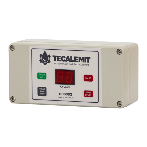
Automatic Lubrication System Controller
WIRING INFORMATION
Refer also to the diagram of the Controller Printed Circuit Board shown on Page 5 of 5
SCREW TERMINAL CONNECTORS: 6 x 2-way plug (Part # MSTB 2.5/2-ST-5.08 by
PHOENIX CONTACT)
LIQUID TIGHT CABLE GLANDS: suit cables 2.9 - 6.4mm OD (Part # 3207 by HEYCO)
24VDC - Power Supply input (Internal fuse: 20 x 5mm 2Amp antisurge)
IP1
- Pressure switch or Cycle switch input (N/O volts-free)
IP2
- Low Level or Remote Test switch input (N/O volts-free)
FAULT - Fault Alarm Relay output (jumper selectable: N/O volts-free contact,
switched 24VDC or 0VDC. Resettable fuse rating: 0.5Amp)
OP1
- Pump SSR output (switched 24VDC, 30Watts)
OP2
- Valve Solenoid SSR output (switched 24VDC, 20Watts)
SSR = Solid State Relay (short circuit protected)
NOTES FOR SETTING TIMERS & OPTIONS (V6.0)
WARNING - Power supply should be switched off and remain off during setup!
(1) Setting DELAY TIME (DSW1) and PUMP ON TIME (DSW2)
Circuit board printed overlay shows location of 8-way DIP switches DSW1 and DSW2.
In the following tables: '1' = switch ON (UP),'0' = switch OFF (DOWN).
Switches 6, 7 & 8 are used to select TIME INCREMENT/Pulsed as follows:
Switch
DSW1 DELAY TIME
DSW1
DSW1
DSW1
DSW2 PUMP ON TIME
DSW2
DSW2
DSW2
DSW2
Setting DELAY TIME (DSW1) and PUMP ON TIME (DSW2) continued.
TC100D2-V6 0 MANUAL Apr 08 A4 (reflowed).docx
TC100D2
(24 VOLT DC)
6
7
8
0
0
0
0
1
0
1
0
0
1
1
0
1
0
0
0
1
0
0
0
1
1
1
1
0
1
1
TIME INCREMENT
2 seconds
1 minute
10 minutes
1 hour
1 second
10 seconds
1 minute
1 second on 1 second off
1 second on 1 second off
X 30 (Total 1 minute)
Page 1 of 6
Advertisement
Table of Contents

Summary of Contents for TECALEMIT TC100D2
- Page 1 DSW2 1 second on 1 second off DSW2 1 second on 1 second off X 30 (Total 1 minute) Setting DELAY TIME (DSW1) and PUMP ON TIME (DSW2) continued. TC100D2-V6 0 MANUAL Apr 08 A4 (reflowed).docx Page 1 of 6...
- Page 2 Controller is powered will not be recognised. If an invalid setting has been made eg. out of range multiplier, the error will be signalled by a flashing ' 0' on the CYCLES display. TC100D2-V6 0 MANUAL Apr 08 A4 (reflowed).docx Page 2 of 6...
- Page 3 See SOFTWARE OPERATION for a detailed description of the PROGRAM and OPTIONS. NOTE : DSW3 must be set prior to power-on. Changes to the switch settings whist the Controller is powered will not be recognised. TC100D2-V6 0 MANUAL Apr 08 A4 (reflowed).docx Page 3 of 6...
- Page 4 When a FAULT is indicated, all outputs are deactivated until the controller is reset by either interrupting power or by pressing the TEST switch on the front panel. Pressing TEST resets the Delay Time period to zero and energises output OP1 immediately. TC100D2-V6 0 MANUAL Apr 08 A4 (reflowed).docx Page 4 of 6...
- Page 5 Level switch input. The Remote Test switch connected to IP2 mimics the TEST switch on the front panel. OPTION 3 - (DSW3 switch 8 ON) This option modifies the base program to cancel the FAULT alarm function ie. Ignore IP1. TC100D2-V6 0 MANUAL Apr 08 A4 (reflowed).docx Page 5 of 6...
- Page 6 Figure 1. TC100D2 Controller Printed Circuit Board TC100D2-V6 0 MANUAL Apr 08 A4 (reflowed).docx Page 6 of 6...

Need help?
Do you have a question about the TC100D2 and is the answer not in the manual?
Questions and answers