Table of Contents
Advertisement
Quick Links
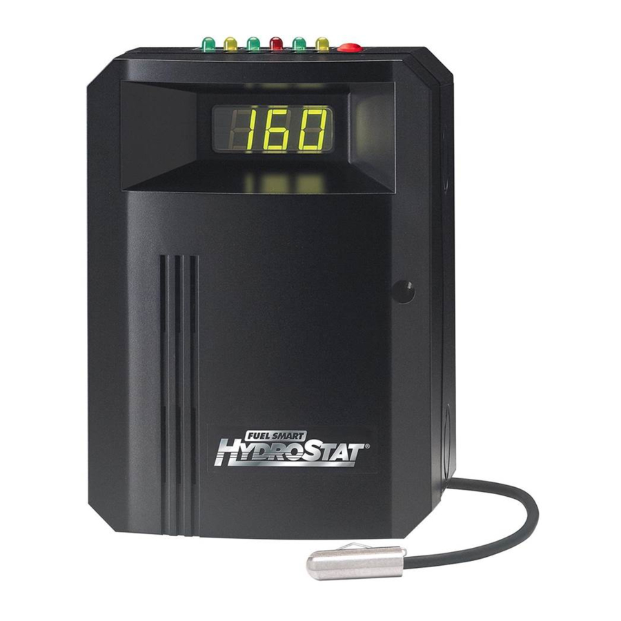
HydroStat 3200- lus
for Slant Fin Boilers
Part Numbers:
48-3200, 48-3200-03
and 48-3200-04
120 VAC Input / 24 VAC Burner Circuit
PATENT NOS.
8.391,708; 7,891,572; 8,844,834;
Others Pending
Three Function
Design
Temperature Limit Control
Designed for cold start and tankless
coil boilers.
Low Water Cut-Off
Provides protection against potentially dangerous
low water conditions when installed with the
Hydrolevel Electro-Well™.
Boiler Reset Control
•
Thermal Targeting – On-board microprocessor
adjusts boiler temperature based on heating demand.
•
Outdoor Reset Ready – Compatible with Hydrolevel
OS-100 Outdoor Sensor Kit (sold separately) for out-
door reset and warm weather shut-down functionality
W RNING
Electrical shock hazard. To prevent electrical shock, death or
equipment damage, disconnect power supply before
installing or servicing control. Only qualified personnel may install or service this control in
accordance with local codes and ordinances. Read instructions completely before proceeding.
W RNING
Frozen pipes/water damage. Central heating systems are prone to shut down as a result of power or fuel outages,
safety related fault conditions or equipment failure. Installation of freeze protection monitoring or other precautions
is recommended for unattended dwellings in climates subject to sustain below-freezing temperatures.
We warrant products manufactured by Hydrolevel Company to be free from defects in
material and workmanship for a period of two years from the date of manufacture or
one year from the date of installation, whichever occurs first. In the event of any claim
under this warranty or otherwise with respect to our products which is made within
such period, we will, at our option, repair or replace such products or refund the pur-
chase price paid to us by you for such products. In no event shall Hydrolevel Company
126 Bailey Road • North Haven, CT 06473 • Phone (203) 776-0473 • F X (203) 764-1711 •
INSTALLATION INSTRUCTIONS
and OPERATING MANUAL
• Saves Fuel – Features Thermal Targeting™ technology and
Thermal Pre-Purge capability
• Outdoor Reset Ready – Provides Outdoor Reset and Warm Weather
Shut-Down capability with the addition of Hydrolevel OS-100 Outdoor
Sensor Kit (sold separately)
• Operating Indicators – LEDs, Dynamic Display and Test Button provide
continual and on-demand status checks
• Prioritizes Domestic Hot Water – Gives priority to low limit setting or to
calls from indirect water heater
LIMITED MANUFACTURER'S WARRANTY
be liable for any other loss or damage, whether direct, indirect, incidental or conse-
quential. This warranty is your EXCLUSIVE remedy and shall be IN PLACE OF any other
warranty or guarantee, express or implied, including, without limitation, any warranty
of MERCHANTABILITY or fitness for a particular purpose. This warranty may not be
assigned or transferred and any unauthorized transfer or assignment thereof shall be
void and of no force or effect.
1
48-3200-03 shown
C UTION
To prevent serious
burns, boiler
should be thoroughly cooled before installing or
servicing control.
www.hydrolevel.com
Advertisement
Table of Contents

Related Manuals for Hydrolevel Company FUEL SMART HydroStat 3200-Plus

Summary of Contents for Hydrolevel Company FUEL SMART HydroStat 3200-Plus
- Page 1 In no event shall Hydrolevel Company void and of no force or effect.
-
Page 2: Specifications
SPECIFICATIONS FUEL SMART HYDROSTAT MODEL 3200- lus Input voltage 120 VAC, 60 HZ Burner contacts 30 VA @ 24 VAC Circulator contacts 5.8 FLA, 34.8 LRA@120 VAC Operating range – low limit Off or 110°F (43°C) - 200°F (93°C) Operating range – high limit 100°F (38°C) - 220°F (104°C) Operating range –... - Page 3 WIRING continued W RNING Electrical shock hazard. To prevent electrical shock, death or equipment damage, disconnect power supply before installing or servicing this control. STEP 6 For Systems with Indirect Water Heaters When installing with an indirect water heater, the signal from the indirect must be separated from the heating zone signals and wired to I1 and I2 as shown above.
-
Page 4: Setting The Control
SETTING THE CONTROL Diagnostic LEDs Test/Settings Jumper Button Dynamic Economy Dial Display (OFF or LO, 1, 2, 3, 4, 5, HI) Water Temperature Factory 1 and Real Time Verification of Setting Adjustments. Indicator Light (announces heat call) Spade Connectors High Temperature for OS-100 Outdoor Limit Setting Sensor Kit... - Page 5 SYSTEM START-UP At initial start up, with the Economy Feature active, the control establishes a 145°F target temperature. To test the high limit shut-off function, the Economy Dial must be turned to OFF. Once tested, restore the Economy setting. If the heating demand is high, the target will increase over time to satisfy the heat load.
-
Page 6: Optional Features
OPTIONAL FEATURES NOTE: The Program Mode – – is accessed by turning the LO TEMP dial to a position just above OFF. Thermal Pre-Purge Thermal Pre-Purge is designed to maximize boiler efficiency. When activated, the control will supply latent heat that may remain in the boiler from a previous run cycle to the next heating zone that calls. - Page 7 OPTIONAL FEATURES continued Circulator Activation Options When in the default mode, the HydroStat activates the circulator (C1/C2 contacts) on calls to T/TV. The control can be pro- grammed to activate the circulator on calls to I1/I2 in place of, or in addition to, calls to T/TV. To change how the Circulator is activated 1.
- Page 8 OPTIONAL FEATURES continued High Limit Differential When the Economy feature is on, the control’s Thermal Targeting feature actively sets varying differentials based on system conditions. This option allows for selecting a 10, 20 or 30 degree fixed differential when the Economy feature is turned OFF. These optional differential settings are subtractive from the HIGH LIMIT setting.
- Page 9 LED LEGEND and TEST/SETTINGS BUTTON TEST/SETTINGS Button To Test Low Water Cut-Off: Press and hold the Test/ Settings button for 5 seconds. The display will read LCO. LWCO TEST The red Low Water light should illuminate and the burner circuit (B1 and B2) should de-energize. NOTE: The control must be installed with a Hydrolevel Electro-Well for low water cut-off functionality (see page 2 for more details).
-
Page 10: Maintenance
MAINTENANCE Remove the Electro-Well from the heating system every five years and clean any scale or sediment deposits from all parts that are exposed to the boiler water. After cleaning, reinstall the well using pipe sealing compound. Teflon tape is not recommended. TROUBLESHOOTING Burner Will Not Fire See Flow Chart 1, page 11... - Page 11 Troubleshooting Flow Chart 1 – Burner Will Not Fire The Control is The Thermal Pre-Purge feature holds off the burner until the Does the Purging Latent control determines if the latent heat in the boiler can satisfy Display Read Heat from the the heat call.
- Page 12 Troubleshooting Flow Chart 2 – Burner Will Not Shut Down Is the The Control is Red LED Sensing (LOW WATER) Low Water. WARNING! TURN OFF POWER TO BURNER IMMEDIATELY! CAUTION – ALWAYS ALLOW A BOILER TO FULLY COOL BEFORE ADDING WATER. Recheck wiring.
Need help?
Do you have a question about the FUEL SMART HydroStat 3200-Plus and is the answer not in the manual?
Questions and answers