Advertisement
Quick Links
INSTALLATION AND MAINTENANCE INSTRUCTIONS
PSP1 Plug-in Special Purpose
Supervisory Switch
Specifications
Dimensions:
Weight:
Enclosure Rating:
Tamper Protection:
Operating Voltage:
Maximum Operating Current:
Operating Temperature:
Important
Please Read Carefully and Save
This instruction manual contains important information
about the installation and operation of this supervisory
switch. This manual should be left with the owner/user of
this equipment.
General Information
The unit is intended for supervision of non-rising stem gate
valves and other valves that cannot be monitored by con-
ventional supervisory switches. Turning the valve wheel
will pull the plug out of the jack and close a set of normally
open contacts. A lockout will prevent reinsertion and re-
quire removal of the cover. Tamperproof screws are pro-
vided for the cover. Removal of cover, or cutting of cord or
ground faults will cause an open circuit. The device should
be wired to the trouble circuit of a fire alarm control panel.
Installation
1. Choose a location near the valve (safe from flooding)
and mount the bracket to the wall.
2. Rotate the box on the bracket until the plug faces the
valve. The plug must also point downward. Tighten the
locknut on the pivot.
3. Turn the valve to the full-open position. Insert the plug
into the jack. Tightly loop the 8-ft. waterproof cable
through the valve wheel and back into the box through
the cable clamp. Close valve to check that plug pulls out
and then turn valve back to full-open position. Cut the
cord to the minimum length required to make the con-
nections within the box.
4. For all exterior applications, use
tight conduit connectors.
5. Wire the device as per the circuit diagrams shown (see
Figures 2-5). Trim the unused black wire flush with the
cable casing and cap the red wire of the cover tamper
switch.
D770-15-00
Technical Manuals Online! - http://www.tech-man.com
4.73" L x 2.94" W x 2.21" D (12 cm L x 7.5 cm W x 5.6 cm D)
With bracket – 8.5" L (21.5 cm L)
1.7 lbs. (.774kg)
Cast-aluminum rain-tight outlet box, Indoor/Outdoor NEMA 3
Cover tamper switch and tamper-proof cover screws
6/12/24 volts AC/DC
250 mA
-4˚ F to 149˚ F (-20˚ C to 65˚ C)
" NPT, listed liquid-
1
/
2
1
3825 Ohio Avenue, St. Charles, Illinois 60174
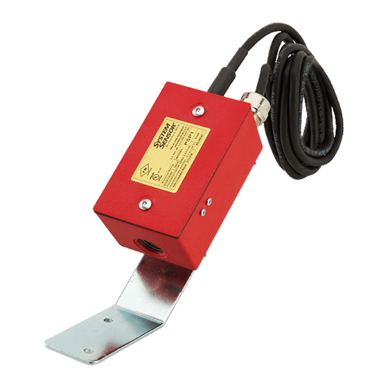
Figure 1. PSP1:
6. If a longer cable is required, use SJOW A 16-2, two con-
ductor 16-gauge stranded rubber-jacketed cable.
7. Using the adhesive pad and wire tie provided, dress the
wires away from the lock-out mechanism.
8. When installing the cover, make sure the O-rings are in
place on the cover screws beneath the cover.
A Division of Pittway
1-800-SENSOR2, FAX: 630-377-6495
I56-984-02
Advertisement

Related Manuals for System Sensor PSP1


Summary of Contents for System Sensor PSP1
- Page 1 INSTALLATION AND MAINTENANCE INSTRUCTIONS PSP1 Plug-in Special Purpose A Division of Pittway 3825 Ohio Avenue, St. Charles, Illinois 60174 Supervisory Switch 1-800-SENSOR2, FAX: 630-377-6495 Specifications Dimensions: 4.73″ L x 2.94″ W x 2.21″ D (12 cm L x 7.5 cm W x 5.6 cm D) With bracket –...
- Page 2 Figure 2. Single device Class B: WARNING As stipulated by Factory Mutual and Underwriter’s Labora- tories, this unit is not intended or designed for ordinary us- age. It is a special application device to be used for unusual conditions where no other approved or listed method of –...
- Page 3 Figure 4. Single device Class A: FACP INITIATING CIRCUIT – FACP SUPERVISORY CIRCUIT – – NOTE: NO OTHER TYPES OF INITIATING DEVICE MAY BE CONNECTED TO THE SAME FACP INITIATING CIRCUIT. WATER-PROOF CABLE VALVE WHEEL Figure 5. Multiple devices Class A: FACP INITIATING CIRCUIT...
- Page 4 60174. Please include a note describing the malfunction and suspected period of three years from date of manufacture. System Sensor makes no cause of failure. The Company shall not be obligated to repair or replace other express warranty for this supervisory switch.
Need help?
Do you have a question about the PSP1 and is the answer not in the manual?
Questions and answers