
Related Manuals for NovaStar VX400s


Summary of Contents for NovaStar VX400s
- Page 1 VX400s LED Display Controller User Manual Rev 1.0.0 NS160100409 Xi’an NovaStar Tech Co., Ltd.
- Page 2 Copyright © 2019 Xi’an NovaStar Tech Co., Ltd. All Rights Reserved. No part of this document may be copied, reproduced, extracted or transmitted in any form or by any means without the prior written consent of Xi’an NovaStar Tech Co., Ltd.
-
Page 3: Table Of Contents
Contents Safety Instructions .......................... 1 Overview ............................2 Front Panel ..........................4 Rear Panel ..........................5 Button Descriptions ........................7 Operations ............................7 Hardware Connection ......................8 Input Settings ........................8 Quick Configuration ......................9 Screen Brightness ......................12 Output Settings ......................... - Page 4 Preset Settings ....................... 24 4.11 Fn ............................24 4.12 Hardware Version ......................25 4.13 Specifications ..........................26 Troubleshooting ........................... 27 -ii-...
-
Page 5: Safety Instructions
1 Safety Instructions To avoid any possible dangers, please use the device according to instructions. There are no user serviceable parts inside. Please refer all servicing to qualified personnel. Danger High Voltage High voltage is present inside the device. To avoid the electric shock, do not remove the rear cover yourself. -
Page 6: Overview
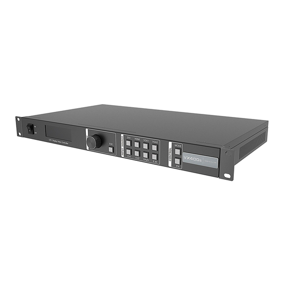
2 Overview The VX400s is a NovaStar professional LED display controller, featuring excellent display control and powerful front-end video processing capabilities. With outstanding image quality and flexible image control functions, the VX400s can greatly satisfy the user needs in media industry. - Page 7 Visualized LCD screen and distinct button indicators simplifies system control operations. Adopts NovaStar G4 engine to realize a perfect display image with no flickering or scanning lines, as well as fine quality and good sense of depth. Adopts NovaStar new-generation calibration technology, allowing for a fast and efficient calibration process.
-
Page 8: Front Panel
2.1 Front Panel ①: Power button ②: Operation screen Row 1: Main layer1, signal source and resolution Row 2: PIP 2, signal source and resolution Row 3: Screen width, height and brightness Row 4: Status bar ... -
Page 9: Rear Panel
: Output port (Ethernet port 2 is used for output) : All the buttons and knob are locked. ③: Knob Press the knob to enter the operation menu screen. Rotate the knob to select a menu item or adjust a parameter. - Page 10 Audio In 1 × Audio input connector HDMI HDMI input connector YPbPr YPbPr input connector 3G-SDI input connector De-interlacing supported DVI input connector VGA1 VGA2 VGA input connector – CVBS1 PAL/NTSC-compliant composite video input CVBS2 PAL/NTSC-compliant composite video input...
-
Page 11: Button Descriptions
UART IN Used as input for device cascading UART OUT Used as output for device cascading For communication with PC Power AC100-240V 50/60Hz AC power connector 3 Button Descriptions Knob: On the home screen, press the knob to enter the operation menu screen. -
Page 12: Hardware Connection
For detailed operations, please see the following chapters. 4.1 Hardware Connection Connect the required hardware devices. VX400s signal connection If you need to control multiple VX400s units, please perform the below connections. Multiple unit connection 4.2 Input Settings 。You can set the input resolution according to your requirements. Currently only... -
Page 13: Quick Configuration
DVI and HDMI connectors supports input resolution settings. If you need to change the input resolution of other connectors, please set it on the device providing the input source. You can set the input resolution via the following two methods. - Page 14 Step 1 Power on the LED screen. If the screen displays normally, go to Step 2. If not, please load the configuration files and save them to the receiving card. For details, please see Advanced Settings. Step 2 On the main menu screen, rotate the knob to select Quick Configuration to enter the quick configuration screen.
- Page 15 Note: a) If the Ethernet port quantity is Example: n (n ≦ 4), the number of If the Ethernet ports 1, 2 and 3 are used to load cabinets loaded the screen, the number of cabinets loaded by Ethernet ports must be the Ethernet port 1 and 2 individually must be the same.
-
Page 16: Screen Brightness
During data flow settings, you must ensure that the Ethernet Port 1 is at the beginning position of the whole physical connection. The maximum loading capacity of the VX400s is 2.3 million pixels (2048x1152@60Hz). The horizontal width can be up to 3840 pixels, then the screen resolution will be 3840x600@60Hz. - Page 17 If the input resolution is larger than the screen resolution, the input source image will not be fully displayed. Turning off the scaling is applicable to the pixel-to-pixel application scenario.
- Page 18 III. Custom scaling Scale is turned on and Auto Scale is turned off. Procedure: Step 1 Rotate the knob to select Input Crop and press the knob to enter the input crop settings screen. Set H Width (no greater than input source width), V Height (no greater than input source height), Initial X and Initial Y.
-
Page 19: Display Control
After the above settings, the LED screen will display the cropped image at the specified position as shown in the below. Input Source Screen Custom scaling 4.6 Display Control Normal: Display the content of current input source normally. -
Page 20: Audio Settings
Transition Effect: Set the transition effect when switching the input source. Rotate the knob to select Cut, Fade or None and press the knob to make the settings take effect. -
Page 21: Advanced Settings
4.8 Advanced Settings Advanced settings include the settings for PIP, Image Mosaic, Load RCFGx Files, Save to RV Card, Hot Backup, Advanced Functions, Factory Reset, Preset Settings, Fn and Hardware Version. 4.8.1 PIP Set to turn on or turn off the PIP function. Rotate the knob to set the main layer source, PIP source, PIP size and position, as well as PIP cropping. - Page 22 Main Layer Source/PIP Source: Select the input sources for main layer and PIP. The function is the same as the function of front panel input source buttons. H Width: Set the PIP width. V Height: Set the PIP height.
-
Page 23: Image Mosaic
-: Main layer and PIP use the same input source. 4.8.2 Image Mosaic When the pixel count of the LED screen is larger than the loading capacity of a single VX400s unit, the image mosaic function is required. -19-... - Page 24 V pixels of the LED screen, lastly set the size and initial position of the area loaded by each VX400s unit. The total loading capacity of all cascaded VX400s units equals to the total pixel count of the LED screen.
-
Page 25: Load Rcfgx Files
Please make sure Scale is set to On and Auto Scale is set to Off. 4.8.3 Load RCFGx Files Connect the VX400s to PC where NovaLCT-Mars is running, and import the configuration files to the controller. 1) Save cabinet configuration file... -
Page 26: Save To Rv Card
3) Load the configuration file. 4.8.4 Save to RV Card You can send and save the screen configuration to the receiving card. The configuration data will not be lost after the device is powered off. -22-... -
Page 27: Hot Backup
4.8.5 Hot Backup You can set the device as primary or backup device. The backup status will be shown on the device home screen. 4.9 Advanced Functions Advanced functions include the following functions: VGA Auto Adjustment: You can adjust the sampling parameters of the VGA input signal to make the VGA image clear and complete. -
Page 28: Factory Reset
4.10 Factory Reset You can reset all user data on the device to factory settings. 4.11 Preset Settings The VX400s supports 10 user presets. User can save, load and clear the configured presets. 4.12 Fn The Fn button on the device front panel can be customized to an Auto Scale, Test Pattern, PIP or Image Mosaic shortcut button. -
Page 29: Hardware Version
Press the Fn button to enter the submenu of the corresponding function. 4.13 Hardware Version You can view the hardware version. If a newer version is released, you can connect the device to LCT-Mars to update the firmware of the VX400s. -25-... -
Page 30: Specifications
5 Specifications Input Connector Qty Description CVBS PAL/NTSC 480i, 576i, 720P, 1080i/P VESA standard Resolution up to 1080p@60Hz VESA standard (1080i input supported) HDCP compliant HDMI EIA/CEA-861 standard, HDMI 1.3 standard compliant HDCP compliant YPbPr Resolution up to 1080p@60Hz... -
Page 31: Troubleshooting
Make sure the power is properly connected and switched on. Make the LED screen is connected properly and works normally. LED screen is Make sure the VX400s has input signal and check whether the not lit screen is black because of extended mode, PIP shielding or other problems. - Page 32 Make sure the input signal is normal. Make sure the audio settings are appropriate. Make sure the audio mode is correct. Make sure the connection between the VX400s and Audio is multifunctional card is in good condition, and the output abnormal Ethernet port icon on the home screen is highlighted.
- Page 33 If problems are still unsolved, please contact your local distributer or our customer service. For your safety, please do not repair the device yourself because there are high voltage components inside the device. -29-...
Need help?
Do you have a question about the VX400s and is the answer not in the manual?
Questions and answers
1 cannot configure my screen. please help
To configure your NovaStar VX400s screen, follow these steps:
1. Save Cabinet Configuration File:
- On NovaLCT, after configuring the screen, save the configuration file (.rcfg) to your PC.
2. Import Configuration File to VX400s:
- Connect the VX400s to your PC and import the cabinet configuration file.
3. Load Configuration File:
- Load the imported configuration file to apply the settings.
4. Save to RV Card (Optional):
- Send and save the screen configuration to the receiving card to ensure the data remains after power-off.
5. Perform VGA Auto Adjustment (If Needed):
- Adjust the VGA input signal sampling parameters for a clear and complete image.
6. Perform ADC Calibration (If Needed):
- Correct color cast or dark image issues for input analog signals (CVBS, VGA, YPBPR).
These steps ensure proper configuration and display performance of the VX400s.
This answer is automatically generated