
Summary of Contents for Linxon LX218
- Page 1 Operating Manual LX218 Leak Detector Catalog No. 8200-000, 8200-001, 8200-002, 8200-003 From software version klna89en1-04-(1908) 1.18...
- Page 2 LINXON is a brand of INFICON GmbH INFICON GmbH Bonner Strasse 498 50968 Cologne, Germany...
-
Page 3: Table Of Contents
4.3.3 Vacuum connections........................ 20 4.3.3.1 Inlet ............................ 20 4.3.3.2 Exhaust gas connection ..................... 21 4.3.3.3 Venting connection...................... 21 4.3.4 Connections for accessories and control signals................ 22 4.4 Technical data ............................ 28 4.4.1 General data .......................... 28 4.4.2 Data on power connections ...................... 29 LX218-Operating-Manual-en1-04-(1908) - Page 4 6.4.10.2 Calibrating in the operation mode "Sniffing"............... 54 6.4.10.3 Checking the calibration using the internal calibration leak .......... 55 6.5 Measuring ............................... 56 6.5.1 Measuring in the operation mode "Vacuum"................ 56 6.5.2 Measuring in the operation mode "Sniffing"................ 56 6.5.3 Measurement view........................ 57 LX218-Operating-Manual-en1-04-(1908)
- Page 5 9 Decommissioning the measuring instrument.................... 79 9.1 Sending in the device .......................... 79 10 Accessories .............................. 81 10.1 Appendix.............................. 81 11 Appendix................................. 83 11.1 Menu path............................... 83 11.1.1 Run-up ............................ 83 11.1.2 Standby............................ 83 11.1.2.1 Configuration........................ 83 11.1.2.2 Calibration .......................... 85 11.2 CE Declaration of Conformity ......................... 86 Index................................ 87 LX218-Operating-Manual-en1-04-(1908)
-
Page 6: About These Instructions
The leak detector distinguishes between the "Vacuum" and "Sniffing" operation modes. For the "Vacuum" operation mode, generally the tracer gas flows into the test object. The pressure in the test object is less than the ambient pressure. 6 / 90 LX218-Operating-Manual-en1-04-(1908) - Page 7 Operation mode "Sniffing": Ambient air is continuously fed into the leak detector via the sniffer line. The amount of helium or hydrogen occurring naturally in air creates a constant background signal. Foreline pressure Pressure of the backing pressure between the turbo molecular pump and the backing pump. LX218-Operating-Manual-en1-04-(1908) 7 / 90...
- Page 8 It produces a slowly decreasing measurement signal. If you want to hide this background signal or the display of existing leaks, then use the ZERO function. 8 / 90 LX218-Operating-Manual-en1-04-(1908)
-
Page 9: Safety
• Operation without exhaust pipe in poorly ventilated rooms, depending on the type of gases used Note: This device is not intended to be used in residential areas and cannot ensure adequate protection of radio reception in such environments. LX218-Operating-Manual-en1-04-(1908) 9 / 90... -
Page 10: Owner Requirements
The measuring instrument was built according to the state-of-the-art and the recognized safety regulations. Nevertheless, improper use may result in risk to life and limb on the part of the user or third parties, or damage to the measuring instrument or other property may occur. 10 / 90 LX218-Operating-Manual-en1-04-(1908) - Page 11 • Take appropriate precautions. Risk of injury from • Place the device only on surfaces that are not tilted. slipping off or falling • Do not lift or carry the device by yourself. down LX218-Operating-Manual-en1-04-(1908) 11 / 90...
-
Page 12: Shipment, Transport, Storage
3 | Shipment, Transport, Storage LINXON 3 Shipment, Transport, Storage Item Quantity LINXON LX218 Power cable Replacement filter for fan Set of fuses Allen key set Centering ring DN 25 ISO-KF Power Subcon plug and housing for D-Sub plug Adapter for ventilation connection... - Page 13 LINXON Shipment, Transport, Storage | 3 Storage Store the device under consideration of the technical data; see "Technical data". See also 2 Inlet [} 20] LX218-Operating-Manual-en1-04-(1908) 13 / 90...
-
Page 14: Description
To scan test objects under overpressure, use the sniffer line. Connect the sniffer line to the back of the device, see "Connections for accessories and control signals [} 22]". This connector is used both to connect the sniffer line and to connect the ventilation line. 14 / 90 LX218-Operating-Manual-en1-04-(1908) -
Page 15: Device Setup
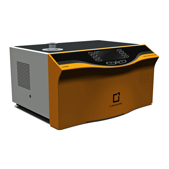
LINXON Description | 4 4.3 Device setup 4.3.1 Overall device Fig. 1: Front view 1 Inlet flange 2 Storage space 3 Operating unit 4 Speaker 5 Front hood 6 Fan opening LX218-Operating-Manual-en1-04-(1908) 15 / 90... - Page 16 2 Remote control connection 3 Electrical connection for the sniffer 4 Gas connection for the sniffer line line or the ventilation line (hose nipple Ø 6/4 mm) 5 Exhaust gas connection (¼‘‘ quick-change connector for hose Ø 8.6 mm) 16 / 90 LX218-Operating-Manual-en1-04-(1908)
-
Page 17: Control Unit
If the button is pressed for more than 3 seconds, background suppression will be disabled. START button START starts the measurement operation. • Switch between the windows by clicking the option buttons on the left and right side of the display. LX218-Operating-Manual-en1-04-(1908) 17 / 90... -
Page 18: Start Button
Adjust volume: The currently adjusted volume is displayed at the bottom edge of the display. The value range is 0 (off) to 15 (max.). Call up the "Configuration" menu. ZERO is active. Call up the calibration. 18 / 90 LX218-Operating-Manual-en1-04-(1908) -
Page 19: Structure Of The Display And Menu
The main display area shows the current state of the device: operation mode, measurement situation, background, tracer gas. Menu name Select the menus by pressing the adjacent round buttons immediately to the left or right of the display. LX218-Operating-Manual-en1-04-(1908) 19 / 90... -
Page 20: Measuring Screen Layout
If you are testing applications with dust or dirt, use the O-ring with filter, see "Shipment, Transport, Storage [} 12]”. In this case, the pump down times are extended. Also use this inlet for the connection of the sniffer line or the test chamber. 20 / 90 LX218-Operating-Manual-en1-04-(1908) -
Page 21: Exhaust Gas Connection
(e.g., fresh air, dry air, nitrogen, etc.) to a maximum of 1.1 mbar pressure. In these cases, a ventilation hose must be connected to the ventilation connection of the device, see "Overall device [} 15]". LX218-Operating-Manual-en1-04-(1908) 21 / 90... -
Page 22: Connections For Accessories And Control Signals
4 | Description LINXON 4.3.4 Connections for accessories and control signals Fig. 6: Linxon interfaces GAUGE Connection for compact measuring tube HEAD INPUT/ Control and output signals OUTPUT RS232 Connection for PC/printer RS485 Connection for PC Remote control or radio transmitter... - Page 23 Reference potential for the digital inputs, galvanically isolated 15 … 22 DO 1 … 8 Digital outputs, not galvanically isolated, active 24 V ± 10%, passive at DGND (0 V) Maximum permissible current: 800 mA for all outputs together LX218-Operating-Manual-en1-04-(1908) 23 / 90...
- Page 24 No Leak Active if the alarm threshold has been undershot. DGND (0 V) Reference potential for the digital outputs, not galvanically isolated +24 V +24 V, e.g., for controlling the digital inputs, 0.8 A slow-blowing fuse 24 / 90 LX218-Operating-Manual-en1-04-(1908)
- Page 25 RJ45 connector (Fig. 10-2/5). The remote control unit is not part of the normal delivery for the device. Signal +24 V (0.8 A slow-blowing fuse) 0 V DGND (0 V) RxD (intern. RS232) LX218-Operating-Manual-en1-04-(1908) 25 / 90...
- Page 26 +24 V (for the power supply of the fieldbus converter; 0.8 A slow-blowing fuse) free free D+ (galvanically isolated) DGND (0 V) D- (galvanically isolated free RS232 Connection for computer. 9-pin, D-Sub sockets, RS232 (RS485 optional). 26 / 90 LX218-Operating-Manual-en1-04-(1908)
- Page 27 Power Subcon connector, 3-pin Fig. 12: Relay LP connection CAUTION The connectors look very similar! There is the risk of confusing the connectors with the "RS485" connector. Connection for sniffer line 3 m, 5 m, 10 m, RJ45, 8-pin LX218-Operating-Manual-en1-04-(1908) 27 / 90...
-
Page 28: Technical Data
+24 V (0.8 A slow-blowing fuse) Green LED: Leak detector is ready for making measurements. Red LED: Threshold is exceeded. 4.4 Technical data 4.4.1 General data LX218 Dimensions 555 mm x 305 mm x 425 mm (LxWxH) Weight With oil-sealed pump... -
Page 29: Data On Power Connections
LINXON Description | 4 LX218 Maximum pressure at the degassing 1.1 bar connection Ingress protection IP 30 Pollution degree Table 1: General information 4.4.2 Data on power connections LX218 Voltage/frequency 8200-000, 8200-002 Dry compressing pump 230V ±10%/50Hz Oil-sealed pump 8200-001 Oil-sealed pump 115V ±10%/60Hz... -
Page 30: Measurement Data
> 2.5 l/s for p < 0.5 mbar inlet Throughput at inlet with large backing depending on the external pump pump (on LX218) Pump-down time for high sensitivity at a volume of 0.5 L at a volume of 10 L 70 s... -
Page 31: Data For The Turbo Pump
He, H Response time < 0.1 s with 3 m sniffer line Table 4: Measuring 4.4.5 Data for the turbo pump SplitFlow 80 Turbo pump with intermediate pumps Volume flow for N2 60 l/s Table 5: Turbo pump LX218-Operating-Manual-en1-04-(1908) 31 / 90... -
Page 32: Installation
The device is heavy and can slip out of hand. ► Do not use the inlet flange to lift the device. ► Lift and transport the device only with two people. ► To lift, grasp the handle grips on the sides of the device. 32 / 90 LX218-Operating-Manual-en1-04-(1908) - Page 33 There is a risk of injury when transporting the device. The device is heavy. ► Only transport the device using two people. Place the device on a level, slip-proof work area. Prevent tripping hazards when placing the device and connecting lines. LX218-Operating-Manual-en1-04-(1908) 33 / 90...
-
Page 34: Connecting To The Power Supply System
Press the Startbutton. ð The inlet is evacuated and then the measuring mode for the measured leak rate is shown. In case a test object was connected, you would start with spraying helium on the outside. 34 / 90 LX218-Operating-Manual-en1-04-(1908) -
Page 35: Connecting An External Backing Pump
Separate the helium calibration leak from the inlet and flange the inlet blind again. Switch off the device via the power supply switch. 5.4 Connecting an external backing pump Final pressure p 0.1 mbar Pumping speed < 6 m³/h Table 6: Specifications for the external backing pump LX218-Operating-Manual-en1-04-(1908) 35 / 90... - Page 36 At the bottom of the device is the DN 25 ISO-KF connection flange. To install the hose, proceed as follows: Lay the device on its side. Place an O-ring between the end of the hose and the connection flange. Clamp both together with a clamping ring. Raise the device up. 36 / 90 LX218-Operating-Manual-en1-04-(1908)
-
Page 37: Operation
Operation mode selection In the "Standby" window, select the "Select operation mode" menu. Select the operation mode "Measuring". Choose between "Vacuum" or "Sniffing". ð The current operation mode is displayed in the "Standby" window. Select "Save". LX218-Operating-Manual-en1-04-(1908) 37 / 90... -
Page 38: Basic Settings
If necessary, you can save your settings at any time to restore an earlier condition. You reach the menus via Standby > Configuration > Global settings • Display • Access control • Maintenance & service • Interfaces 38 / 90 LX218-Operating-Manual-en1-04-(1908) -
Page 39: Setting The Display
Settings Measurement units Comments Leak rate mbar*l/s Pa*m3/s Torr*l/s sccm sccs atm*cc/s Only available in the operation mode "Sniffing" Only available in the operation mode "Sniffing" oz/yr Only available in the operation mode "Sniffing" Pressure mbar LX218-Operating-Manual-en1-04-(1908) 39 / 90... - Page 40 In the measuring mode, you can set a lower limit for the display of the leak rate. The setting is only effective for the "Vacuum" operation mode. Options Value range (min./max.) Comments Lower display limit With the units mbar*l/s: The display limit only affects the operation mode 1E-12 mbar*l/s "Vacuum". 40 / 90 LX218-Operating-Manual-en1-04-(1908)
-
Page 41: Access Control
Options Value range Comments Maintenance activated Access to the "Maintenance and service" menu is enabled. The TMP can be vented during run- Access to the "Maintenance and service" menu is not enabled. The LX218-Operating-Manual-en1-04-(1908) 41 / 90... - Page 42 Authorization for the device is active if the current device PIN is not 0000. If you activate authorization for the device, you have to save the device PIN. If you have forgotten the device PIN, contact Linxon. Options Value range (min./max.)
-
Page 43: Loading/Saving Parameters
The setting can be changed during this time. The correct menu PIN must then be entered to access all the menus. If you activate permission for the menu, be sure to save the menu PIN. If you have forgotten the menu PIN, contact Linxon. Options Value range (min./max.) -
Page 44: Volume And Beeping
Connect the sniffer line before pressing START Mass (2 amu) Detectable gas H He (3 amu) Detectable gas He (4 amu) Detectable gas Leak rate factor Factor Leak rate converted using user-defined factor 1E-6 … 1E+6 44 / 90 LX218-Operating-Manual-en1-04-(1908) -
Page 45: Setting Filter And Zero
Options Value range (min./max.) Comments Filter Dynamic Leak rate filter with dynamic time constant setting Static Leak rate filter with fixed time constant none No leak rate filter ZERO Enabled Manual background suppression activated LX218-Operating-Manual-en1-04-(1908) 45 / 90... - Page 46 With the activation of "START", this currently measured internal background is automatically subtracted from all further measurements. This ensures that only the net leak rate of the test object is measured. 46 / 90 LX218-Operating-Manual-en1-04-(1908)
-
Page 47: Setting Vacuum Ranges
If you have questions, contact the manufacturer. Standby > Configuration > Test settings > Vacuum ranges These settings can only be set for the operation mode "Vacuum": Options Value range (min./max.) Comments ULTRA Activated Activated LX218-Operating-Manual-en1-04-(1908) 47 / 90... -
Page 48: Setting The Evacuation Time And Ventilation
If this time is exceeded, the pump down operation stops before reaching the final pressure of 15 mbar and an error message is displayed. Venting Manual The test connection can be vented by pressing "Vent" in the "Standby" window. 48 / 90 LX218-Operating-Manual-en1-04-(1908) -
Page 49: Setting Gross Leak Protection
Options Value range (min./max.) Comments Protection Gross leak protection is switched on Gross leak protection is switched off Limit value 1E-9 ... 1E+3 mbar*l/s) Switch-off limit for the gross leak protection function LX218-Operating-Manual-en1-04-(1908) 49 / 90... -
Page 50: Setting Pressure Limits For Operation Mode "Sniffing
The frequency range is 300 Hz to 3300 Hz. Trigger alarm If the leak rate is below the warning limit, no sound is 0 min, 10 min output. If the leak rate is greater 50 / 90 LX218-Operating-Manual-en1-04-(1908) -
Page 51: Defining The Calibration Settings
Specify whether the device displays a calibration request after standard events occur. Option Comments The calibration request is carried out. – 30 minutes after switching the device on - if the temperature in the device has changed by more than 5 °C since the last calibration. LX218-Operating-Manual-en1-04-(1908) 51 / 90... -
Page 52: Calibrating
The inlet flange must be empty. • Internal manual: For calibration with the internal calibration leak with volume at the inlet flange. By pressing "Signal stable", it must be confirmed that a stable measurement signal is present. 52 / 90 LX218-Operating-Manual-en1-04-(1908) - Page 53 Fig. 14: External calibration, partial flow 1 Calibration leak 2 Test chamber 3 Leak detector If the device is connected to a vacuum system with an integrated vacuum pump, connect the calibration leak to its test container. LX218-Operating-Manual-en1-04-(1908) 53 / 90...
-
Page 54: Calibrating In The Operation Mode "Sniffing
1. Accept or reject the calibration performed. To accept the result, select "Save". Otherwise, select "Cancel". If typical values are not reached despite repeated attempts, contact your nearest Linxon Service Center. 6.4.10.2 Calibrating in the operation mode "Sniffing" NOTICE Observe the recommended test interval for the calibration leak used! Also see the quality test certificate for the calibration leak. -
Page 55: Checking The Calibration Using The Internal Calibration Leak
Operation | 6 7. If the typical values are not reached despite repeated attempts, contact your nearest Linxon Service Center 6.4.10.3 Checking the calibration using the internal calibration leak This function is available for the "Vacuum" operation mode and with mass 4. For this measurement, the test port must be blind-flanged. -
Page 56: Measuring
Suctioned fluids can trigger short circuits and cause material damage or injuries. Do not suck up liquids into the device. 1. Connect all required accessories or devices. Make sure that a sniffer line is connected and the test port is free. 56 / 90 LX218-Operating-Manual-en1-04-(1908) -
Page 57: Measurement View
Run-up > Configuration > Information • Settings • System data • Vacuum diagram • Error list • Calibration history You can also locate the installed remote control using an acoustic signal: Standby > Configuration > Information > Paging function LX218-Operating-Manual-en1-04-(1908) 57 / 90... - Page 58 This contains the error description as well as information on possible causes and corrective measures. Calibration history Standby > Configuration > Information > Calibration history 58 / 90 LX218-Operating-Manual-en1-04-(1908)
-
Page 59: Calibrating With Vacuum Method
Confirmation of a stable measurement signal by means of the "Signal stable" button is necessary. External calibration leak For a calibration leak, the following prompt appears: "External calibration: Connect and open external calibration leak". LX218-Operating-Manual-en1-04-(1908) 59 / 90... - Page 60 CAUTION Part flow arrangement If the device is connected to a vacuum system with its own pump, the calibration leak must be connected to its test container. Fig. 16: Calibration The calibration runs through the following sequences: 60 / 90 LX218-Operating-Manual-en1-04-(1908)
- Page 61 During a calibration with external tracer gas or internal tracer gas in the "Manual internal" mode, the stability of the signal must be confirmed using the OK button. After the end of the calibration process, the result is displayed. LX218-Operating-Manual-en1-04-(1908) 61 / 90...
-
Page 62: Calibrating With Sniff Method
• do not accept the result, press "Cancel" to leave the old values in place. If the common values cannot be reached despite multiple attempts, please contact your nearest Linxon Service Center. 6.8 Calibrating with sniff method For optimal calibration, the device must be warmed up for at least 30 minutes. - Page 63 Confirm the stability of the signal with the OK button. Now the following prompt appears: • Remove sniffer line from the calibration leak • Confirm with OK or the button on the sniffer line After the end of the calibration process, the result is displayed. LX218-Operating-Manual-en1-04-(1908) 63 / 90...
-
Page 64: Check Internal Calibration Leak
• do not accept the result, press "Cancel" to leave the old values in place. If the common values cannot be reached despite multiple attempts, please contact your nearest Linxon Service Center. 6.9 Check internal calibration leak Standby > Calibration > Check internal calibration leak This function is only available for the "Vacuum"... -
Page 65: Warning And Error Messages
• The anode voltage is short-circuited. • The nominal value for the anode voltage is too high. The anode voltage is limited to 1,200 V. Suppressor test incorrect! • MSV board defective • Preamplifier defective • Suppressor cable defective LX218-Operating-Manual-en1-04-(1908) 65 / 90... - Page 66 • MSV is defective Suppressor potential too Suppressor potential is less than U < 297 V. low. • Short circuit in the suppressor line. • MSV is defective. • High ohmic short circuit in the ion collector. 66 / 90 LX218-Operating-Manual-en1-04-(1908)
- Page 67 Emission is switched off during normal operation of the leak detector when the pressure in GROSS is p2 > (GROSS pressure threshold + 5 mbar) or in FINE is p2 > (FINE pressure threshold + 1 mbar) or LX218-Operating-Manual-en1-04-(1908) 67 / 90...
- Page 68 • Sensor electronics I/O board is defective p1 > 10 mbar after run-up The foreline pressure P1 is > 10 mbar after 5 min. in run-up • Backing pump is defective • Leaks in the vacuum system • Valve V1 does not open 68 / 90 LX218-Operating-Manual-en1-04-(1908)
- Page 69 • Connection is faulty or not plugged in TC 110 – wiring level • TC 110 defective • MC 68 is defective The offset voltage of the • The preamplifier is defective. preamplifier is too high. (> 5 • Incorrect power supply to preamplifier LX218-Operating-Manual-en1-04-(1908) 69 / 90...
- Page 70 W103 Flow through capillary is • Filter in filter tip is clogged too low! • Sinter filter in filter tip is soiled • Capillary is clogged by dirt • Lower flow limit is set incorrectly 70 / 90 LX218-Operating-Manual-en1-04-(1908)
- Page 71 The time limit is specified by the set maximum evacuation time in the configuration menu. W121 The calibration leak signal • The calibration leak used for the is too small! calibration is too small. LX218-Operating-Manual-en1-04-(1908) 71 / 90...
- Page 72 • The calibration leak is defective or empty. • The calibration leak value entered for the calibration leak is too large. • Mass spectrometer soiled and non- sensitive. • The conditions necessary for calibration have not been satisfied. 72 / 90 LX218-Operating-Manual-en1-04-(1908)
- Page 73 • Temperature sensor defective. After confirmation of this warning message, a warning triangle will remain in the "Ready" menu, indicating the presence of this fault. Only if this fault is eliminated will this warning triangle disappear. LX218-Operating-Manual-en1-04-(1908) 73 / 90...
- Page 74 • MC 68 control board is defective • Line connection to EEPROM is interrupted • Wrong EEPROM type is used W145 x EEPROM parameters Missing or changed parameter in the installed! Please check the EEPROM and new software version number settings! determined. 74 / 90 LX218-Operating-Manual-en1-04-(1908)
- Page 75 Within the set evacuation time, the exceeded! "Measuring" state has not been reached. • Evacuation time is adapted incorrectly to the sample volume. • DUT has a gross leak. • Switching pressures set incorrectly. Table 8: Warnings LX218-Operating-Manual-en1-04-(1908) 75 / 90...
-
Page 76: Cleaning And Maintenance
► Do not open the side walls of the device! Cleaning the housing Wipe the housing with a soft damp cloth. Use only water to moisten. Avoid cleaners that contain alcohol, fat or oil. Make sure that the rating plate is preserved. 76 / 90 LX218-Operating-Manual-en1-04-(1908) -
Page 77: Cleaning/Replacing The Filter Mat For Fan 1
• To clean or replace the filter mat, pull the filter mat forward and out. • Clean the filter with compressed air. • Replace the filter if heavily soiled. LX218-Operating-Manual-en1-04-(1908) 77 / 90... -
Page 78: Replacing Power Fuses
Remove both fuse holders and replace defective (10.0 A slow-blowing, 250 V, Ø 5 x 20 mm) fuses. Fig. 19: Removing fuses 1. Snap the fuse holders back into place. 2. Close the cover. 3. Reconnect the power cable. 78 / 90 LX218-Operating-Manual-en1-04-(1908) -
Page 79: Decommissioning The Measuring Instrument
► Fill in the declaration of contamination completely. Contact Linxon before making a return shipment and send a completed contamination declaration. ð You will then receive a return number. - Page 80 9 | Decommissioning the measuring instrument LINXON 80 / 90 LX218-Operating-Manual-en1-04-(1908)
-
Page 81: Accessories
It offers the advantage of easy wireless operation of the leak detector from a distance of up to 100 m and can also be connected via a cable to the leak detector. (Also see the RC1000 WL/RC1000 instruction manual) LX218-Operating-Manual-en1-04-(1908) 81 / 90... - Page 82 5. LED operation – Signals operation of the remote control by flashing. 6. LED charge indicator – Lights up while the battery is being charged. The remote control is an optional accessory, therefore it is not part of the standard scope of delivery. 82 / 90 LX218-Operating-Manual-en1-04-(1908)
-
Page 83: Appendix
Standby > Configuration > Global settings > Access control > Change device PIN Standby > Configuration > Global settings > Access control > Change menu PIN Maintenance and Standby > Configuration > Global settings > Maintenance and Service > Device service maintenance LX218-Operating-Manual-en1-04-(1908) 83 / 90... - Page 84 Standby > Configuration > Information > System data Standby > Configuration > Information > Vacuum diagram Standby > Configuration > Information > Error list Standby > Configuration > Information > Calibration history Standby > Configuration > Information > Paging function 84 / 90 LX218-Operating-Manual-en1-04-(1908)
-
Page 85: Calibration
Standby > Configuration > Test settings > Gross leak protection Standby > Configuration > Test settings > Pressure limits for sniffing mode 11.1.2.2 Calibration Standby > Calibration > Background reassessment Standby > Calibration > Check internal calibration leak LX218-Operating-Manual-en1-04-(1908) 85 / 90... -
Page 86: Ce Declaration Of Conformity
11 | Appendix LINXON 11.2 CE Declaration of Conformity 86 / 90 LX218-Operating-Manual-en1-04-(1908) -
Page 87: Index
76 Connecting the sniffer line 14 Declaration of Contamination 79, 80 Definition of terms 6 Function description 14 Maintenance 76 Operation mode "Vacuum" 14 O-Ring with filter 20 Return 79 Switch OFF 64 Switching on 37 LX218-Operating-Manual-en1-04-(1908) 87 / 90... - Page 88 Index LINXON 88 / 90 LX218-Operating-Manual-en1-04-(1908)
Need help?
Do you have a question about the LX218 and is the answer not in the manual?
Questions and answers