Table of Contents
Advertisement
Quick Links
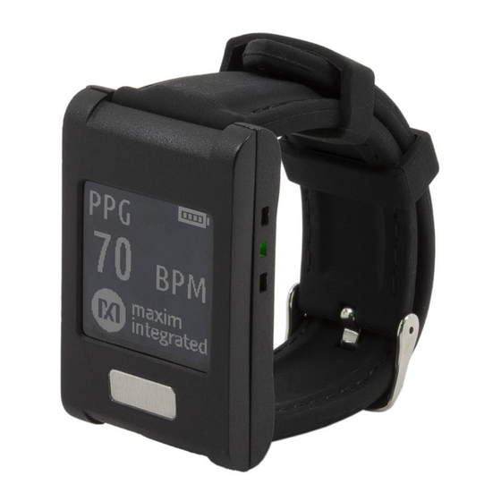
MAXREFDES101#: Health Sensor Platform 2.0
User Guide
UG6780; Rev 2; 8/19
Abstract
This user guide provides information about preparing and running the MAXREFDES101# Health
Sensor Platform. This platform uses several biosensors, power-management ICs (PMIC), and
®
microcontrollers from Maxim Integrated
in a wrist worn design that allows the capture of
biosignals important to healthcare. The platform also contains algorithms for calculating heart
health based on the biosensor measurements.
Maxim Integrated
Page 1 of 39
Advertisement
Table of Contents

Related Manuals for Maxim Integrated MAXREFDES101

Summary of Contents for Maxim Integrated MAXREFDES101
- Page 1 MAXREFDES101#: Health Sensor Platform 2.0 User Guide UG6780; Rev 2; 8/19 Abstract This user guide provides information about preparing and running the MAXREFDES101# Health Sensor Platform. This platform uses several biosensors, power-management ICs (PMIC), and ® microcontrollers from Maxim Integrated in a wrist worn design that allows the capture of biosignals important to healthcare.
-
Page 2: Table Of Contents
How to Wear the Device ......................10 PPG Measurement ......................10 ECG Measurement ......................10 Body Temperature Measurement ..................10 Installing the PC GUI.........................11 Upgrading the Firmware on MAXREFDES101# ................12 Updating the Sensor Hub Algorithm ..................13 Using the PC GUI ........................16 USB Connection ........................16 BLE Connection ........................19 Starting the ECG Measurement .....................20... - Page 3 List of Figures Figure 1. MAXREFDES101# wearable form factor in detail............5 Figure 2. MAXREFDES101# exploded view................5 Figure 3. MAXREFDES101# system diagram................7 Figure 4. USB Type-C cable (left) and Pico adapter board (right)..........8 Figure 5. Watch display modes....................9 Figure 6.
- Page 4 Figure 41. Log file Temp_.csv for body temperature measurement...........38 List of Tables Table 1. PPG Raw Data Table Column Definitions (PPG_*.csv) ..........36 Table 2. ECG Raw Data Table Column Definitions (ECG_*.csv) ..........37 Table 3. Temperature Raw Data Table Column Definitions (TEMP_*.csv) ........38 Maxim Integrated Page 4 of 39...
-
Page 5: Detailed Hardware Description
Detailed Hardware Description Figure 1. MAXREFDES101# wearable form factor in detail. Figure 2. MAXREFDES101# exploded view. Maxim Integrated Page 5 of 39... -
Page 6: Required Equipment
Required Equipment The MAXREFDES101# platform includes the following components: • Micro board that includes: o MAX32630 microcontroller o MAX20303 power-management IC (PMIC) o Dual mode Bluetooth ® o Six-axis accelerometer and gyroscope • Sensor board that includes: o MAX86141 analog front end and optical heart-rate sensor with one green LED... -
Page 7: System Diagram
System Diagram Figure 3. MAXREFDES101# system diagram. Maxim Integrated Page 7 of 39... -
Page 8: Operating The Watch
The left connector next to the “DEVICE” label is used for the serial connection between the MAXREFDES101# and the PC. Both connectors provide power to the MAXREFDES101#. -
Page 9: Display Modes
Figure 5. Watch display modes. Note: There is no display in ECG mode because the noise from the display interferes with the measurement. To take an ECG measurement, use the PC or Android application. Maxim Integrated Page 9 of 39... -
Page 10: How To Wear The Device
Note: For best results on Windows 7, flash logging is recommended to avoid noise over the USB cable. Figure 7. ECG measurement. Body Temperature Measurement To take a body temperature measurement, wear the watch on the wrist and make sure the skin has direct contact with electrode 2. Maxim Integrated Page 10 of 39... -
Page 11: Installing The Pc Gui
Installing the PC GUI 1. Download and extract the Eval Package for either Windows 10 or Windows 7 from the Software section on the MAXREFDES101# Design Resources tab. Note: The software package includes the latest firmware, algorithm, and the corresponding Windows or Android application. All three must be updated to ensure compatibility. -
Page 12: Upgrading The Firmware On Maxrefdes101
Upgrading the Firmware on MAXREFDES101# The micro board might be shipped without the latest firmware. Maxim recommends that you update the firmware whenever new firmware becomes available. Firmware upgrades can be performed using the provided Pico adapter board by performing the following steps: 1. -
Page 13: Updating The Sensor Hub Algorithm
® 2. Open the Maxim DeviceStudio Windows application. 3. Select the “Serial over USB” Scan Option. Click “Scan.” Figure 11. Maxim DeviceStudio scan options. Maxim is a registered trademark of Maxim Integrated Products, Inc. Maxim Integrated Page 13 of 39... -
Page 14: Figure 12. Maxim Devicestudio Connected Devices
5. Go to Device Tab > Update SmartSensor_MAX32660 Software > Update Firmware and select the *.msbl file from the extracted Eval Package. 6. The embedded heart rate algorithm is uploaded to the MAX32664 microcontroller on the sensor board. Maxim Integrated Page 14 of 39... -
Page 15: Figure 13. Upload Embedded Heart-Rate Algorithm To The Max32664
Figure 13. Upload embedded heart-rate algorithm to the MAX32664. Maxim Integrated Page 15 of 39... -
Page 16: Using The Pc Gui
Using the PC GUI The Windows 10 PC GUI currently supports connection to the MAXREFDES101# through USB or Bluetooth Low Energy (BLE). The Windows 7 PC GUI only supports connection to the MAXREFDES101# through USB. USB Connection 1. Connect the watch to the PC with a USB Type-C cable (or with the Pico adapter board with a USB Micro-B cable). -
Page 17: Figure 15. Scan For Devices
2. Under Scan Mode, select “Serial over USB.” Click “Scan.” Figure 15. Scan for devices. Maxim Integrated Page 17 of 39... -
Page 18: Figure 16. Successful Connection Over Usb
3. Verify that Connected Devices lists ECG, TEMP, and PPG. Figure 16. Successful connection over USB. Maxim Integrated Page 18 of 39... -
Page 19: Ble Connection
2. Select the device with the MAC address that matches the MAC address listed on the watch info screen. Click “Connect.” Figure 17. BLE device selection. 3. Verify that Connected Devices lists ECG, TEMP, and PPG. Figure 18. Successful connection over BLE. Maxim Integrated Page 19 of 39... -
Page 20: Starting The Ecg Measurement
MAX30001 data sheet for a detailed explanation of the parameters. Click on “Start Monitoring.” Note: There is no display in ECG mode because the noise from the display interferes with the measurement. Figure 19. Start the ECG measurement. Maxim Integrated Page 20 of 39... -
Page 21: Figure 20. Ecg Measurement Sample
Figure 20. ECG measurement sample. Maxim Integrated Page 21 of 39... -
Page 22: Starting The Temperature Measurement
3. Check the box for “Log to Flash” to save the data to the on-board flash. Data is not streamed to the GUI while Flash Logging is enabled. 4. Select the Sample Interval in seconds. 5. Click on “Start Monitoring.” Figure 21. Start the temperature measurement. Maxim Integrated Page 22 of 39... -
Page 23: Starting The Ppg Measurement
Refer to the MAX86141 data sheet for a detailed explanation of the AFE settings. 7. Select Algorithm mode to allow the MAX32664 HRM algorithm to dynamically adjust the AFE settings. 8. Click on “Start Monitoring.” Figure 22. Start the PPG measurement. Maxim Integrated Page 23 of 39... -
Page 24: Figure 23. Ppg Measurement Sample
Figure 23. PPG measurement sample. Maxim Integrated Page 24 of 39... -
Page 25: Installing The Android App
Play Store. 2. Download the Android Eval Pack using the web browser on the Android device from the Software section on the MAXREFDES101# Design Resources tab. 3. Open Downloads or an Android file browser and unzip the downloaded file. Once extracted, open the AndroidApp_HSP2 folder. -
Page 26: Using The Android App
2. Tap the device with the MAC address that matches the MAC address listed on the watch info screen. 3. Verify that Electrocardiogram, Optical HRM, and Temperature are displayed. Figure 26. Mode selection view. Maxim Integrated Page 26 of 39... -
Page 27: Starting The Ecg Measurement For Android
Data is not streamed to the app while Flash Logging is enabled. 5. Tap “Start Monitoring.” Figure 27. Start the ECG measurement for the Android app. Note: There is no display in ECG mode because the noise from the display interferes with the measurement. Maxim Integrated Page 27 of 39... -
Page 28: Figure 28. Android App Ecg Measurement Sample
7. Wear the watch on the wrist and make sure the skin has direct contact with electrodes 2 and 3. Then place a finger from the opposite hand on electrode 1. 8. Tap “INVERT ECG” to invert the ECG waveform if needed. Figure 28. Android app ECG measurement sample. Maxim Integrated Page 28 of 39... -
Page 29: Starting The Ppg Measurement For Android
4. Wear the watch on the wrist and make sure the skin has direct contact with the LED/photodiodes at the center of the back of the watch. 5. Tap “Start Monitoring.” Figure 29. Android app PPG measurement sample. Maxim Integrated Page 29 of 39... -
Page 30: Starting The Temperature Measurement For Android
5. Tap the Sample Interval dropdown to select the Sample Interval in seconds. 6. Wear the watch on the wrist and make sure the skin has direct contact with electrode 2. 7. Tap “Start Monitoring.” Figure 30. Start the temperature measurement for the Android app. Maxim Integrated Page 30 of 39... -
Page 31: Figure 31. Android App Temperature Measurement Sample
Figure 31. Android app temperature measurement sample. Maxim Integrated Page 31 of 39... -
Page 32: Installing The Windows 7 Driver
2. Extract the .zip file to a known location. 3. Open Device Manager. Device Manager can be found in the Control Panel. 4. If manual driver installation is needed, the MAXREFDES101# appears under Other devices as “CDC DEVICE.” Right-click “CDC DEVICE” and select Properties. -
Page 33: Figure 34. Browse To Extracted Release Package
8. When prompted by the Windows Security window, click “Install this driver software anyway.” Figure 35. Choose Install this driver software anyway. 9. After the driver is installed successfully, the MAXREFDES101# appears as an mbed Serial Port. Figure 36. mbed Serial Port in Device Manager. -
Page 34: Flash Logging
Figure 37. MSD connection to PC using USB Type-C cable (left) and Pico adapter board (right). 4. The device appears in Windows Explorer as a USB Drive, and you can copy-paste files from the device. 5. Copy the “.maximlog” file to your PC hard drive. Maxim Integrated Page 34 of 39... -
Page 35: Figure 38. Flash Log Parser
6. In the PC GUI, open the Flash Log Parser from the Tools menu. 7. Select the “.maximlog” file, choose an output folder, and click PARSE. A .csv file is generated in the output folder containing the parsed log file. Figure 38. Flash Log Parser. Maxim Integrated Page 35 of 39... -
Page 36: Data Format
3: Running activity. HR confidence threshold: 30%. 4: Biking activity. HR confidence threshold: 30%. 5: Rhythmic activities that cannot be classified in the other categories. HR confidence threshold: 30%. Figure 39. Log file PPG_.csv for PPG measurement. Maxim Integrated Page 36 of 39... -
Page 37: Figure 40. Log File Ecg_.Csv For Ecg Measurement
MAX30001 PTAG [2:0] ECG PACE data tag (see table 49 in data sheet for details) MAX30001 R-to-R (bpm) Heart rate (beats per min) Figure 40. Log file ECG_.csv for ECG measurement. Maxim Integrated Page 37 of 39... -
Page 38: Figure 41. Log File Temp_.Csv For Body Temperature Measurement
Sample count Data index ranging from 0 to 255 for monitoring if samples are dropped during Bluetooth transmission Temperature (°C) Temperature in units of Celsius Figure 41. Log file Temp_.csv for body temperature measurement. Maxim Integrated Page 38 of 39... -
Page 39: Revision History
Flash Logging section. ©2019 by Maxim Integrated Products, Inc. All rights reserved. Information in this publication concerning the devices, applications, or technology described is intended to suggest possible uses and may be superseded. MAXIM INTEGRATED PRODUCTS, INC.
Need help?
Do you have a question about the MAXREFDES101 and is the answer not in the manual?
Questions and answers