Table of Contents
Advertisement
Quick Links
Advertisement
Table of Contents

Related Manuals for TYAN TN76A-B8242


Summary of Contents for TYAN TN76A-B8242
- Page 1 TN76A-B8242 Service Engineer’s Manual http://www.tyan.com...
- Page 2 http://www.tyan.com...
- Page 3 MiTAC assumes no liability whatsoever, and ® disclaims any express or implied warranty, relating to sale and/or use of TYAN products including liability or warranties relating to fitness for a particular purpose or merchantability. MiTAC retains the right to make changes to produce descriptions and/or specifications at any time, without notice.
- Page 4 This Class A digital apparatus complies with Canadian ICES-003. Cet appareil numérique de la Classe A est conforme à la norme NMB-003 du Canada. Notice for Europe (CE Mark) This product is in conformity with the Council Directive 2014/30/EU. http://www.tyan.com...
- Page 5 Replace only with the same or equivalent type recommended by manufacturer. Dispose of used battery according to manufacturer instructions and in accordance with your local regulations. ● VCCI-A この装置は、クラスA情報技術装置です。この装置を家庭環境で使用すると電波 妨害を引き起こすことがあります。 この場合には使用者が適切な対策を講ずるよう 要求されることがあります。 ● Safety: IEC/EN 60950-1 This equipment is compliant with CB/LVD of Safety: IEC/EN 60950-1. http://www.tyan.com...
- Page 6 How this guide is organized This guide contains the following parts: Chapter 1: Overview This chapter provides an introduction to the TYAN TN76A-B8242 barebones and standard parts list, describes the external components, gives an overview of the product from different angles.
- Page 7 Safety and Compliance Information Before installing and using TYAN TN76A-B8242, take note of the following precautions: ·Read all instructions carefully. ·Do not place the unit on an unstable surface, cart, or stand. ·Do not block the slots and opening on the unit, which are provided for ventilation.
- Page 8 You must become familiar with the safety information in this guide before you install, operate, or service TYAN products. Symbols on Equipment Caution. This symbol indicates a potential hazard.
- Page 9 · Do not attempt to move a fully loaded rack. Remove equipment from the rack before moving it. · Do not attempt to move a rack on an incline that is greater than 10 degrees from the horizontal. http://www.tyan.com...
- Page 10 This will reduce the risk of personal injury, fire, or damage to the equipment. The total rack load should not exceed 80 percent of the branch circuit rating. Consult the electrical authority having jurisdiction over your facility wiring and installation requirements. http://www.tyan.com...
- Page 11 TYAN, your authorized TYAN partner, or their agents. Equipment Modifications · Do not make mechanical modifications to the system. TYAN is not responsible for the regulatory compliance of TYAN equipment that has been modified.
- Page 12 – The product has been dropped or damaged. – The product does not operate normally when you follow the operating instructions. Warning:This equipment is compliant with Class A of CISPR 32. In a residential environment this equipment may cause radio interference. http://www.tyan.com...
-
Page 13: Table Of Contents
Table of Contents Chapter 1: Overview ................ 15 About the TYAN TN76A-B8242 ..........15 Product Models ............... 15 Features.................. 16 Standard Parts List ..............27 1.4.1 Box Contents ..............27 1.4.2 Accessories ..............28 About the Product ..............29 1.5.1 System Front View ............ - Page 14 Appendix I: How to recover UEFI BIOS ........176 Appendix II: Cable Connection Tables ........178 Appendix III: FRU Parts Table ............181 Appendix IV: Fan and Temp Sensors .......... 183 Appendix V: Installing IO Plate for OCP Card ......187 Appendix VI: Technical Support ........... 189 http://www.tyan.com...
-
Page 15: Chapter 1: Overview
2.5’7/9mm hot-swapped SATA/ NVME hard drives. The TN76A-B8242 uses TYAN’s latest chassis featuring a robust structure and a solid mechanical enclosure. All of this provides TN76A-B8242 the power and flexibility to meet the needs of nowadays server application. Product Models... -
Page 16: Features
Efficiency 80 plus Platinum Redundancy Q'ty / Socket Type (2) AMD Socket SP3 (2) AMD EPYC™ 7000 Series Supported CPU Processor Series Processors Thermal Design Max up to 200W Power (TDP) Wattage Memory Supported DIMM Qty (16)+(16) DIMM slots http://www.tyan.com... - Page 17 PCI-E Gen3 x16 + (2) PCI-E Gen3 x8 slots (right) (1) M7106-R24-3F riser card for (1) PCI-E Gen3 x16 + Expansion Slots Pre-install TYAN (2) PCI-E Gen3 x8 slots (right) , (1) Riser Card M8242T76-L16-2F # riser card for (PCI-E Gen3)
- Page 18 USB device/PXE via BIOS Feature LAN/Storage, Console Redirection, ACPI sleeping states S0,S1,S5, FAN speed control automatic, ACPI 6.0 Please refer to our AVL support Operating System OS supported list lists. FCC (DoC) Class A Regulation CE (DoC) Class A http://www.tyan.com...
- Page 19 - 40° C ~ 70° C (-40° F ~ 158° F) Operating Environment In/Non-operating 90%, non-condensing at 35° C Humidity RoHS RoHS 6/6 Compliant Barebone (1) TN76A-B8242 Barebone Package Contains Manual (1) Quick Installation Guide B8242T76AV18E8HR-2V Specifications Form Factor 2U Rackmount Chassis Model...
- Page 20 (HH, HL) (1) M7106-L24-3F riser card for (1) PCI-E Gen3 x16 + (2) PCI-E Gen3 x8 slots (right) , (1) Pre-install TYAN M8242T76-L16-2F # riser card for Riser Card (1) PCI-E Gen3 x16 slot + (1) PCI-E (PCI-E Gen3)
- Page 21 Voltage System Monitoring chipset & power supply Over temperature warning indicator, Fan & PSU fail LED indicator Others Watchdog timer support Onboard Chipset Onboard Aspeed AST2500 Server Management AST2500 iKVM 24-bit high quality video Feature compression, Supports storage over http://www.tyan.com...
- Page 22 10° C ~ 35° C (50° F~ 95° F) Non-operating Temp. - 40° C ~ 70° C (-40° F ~ 158° F) Operating Environment In/Non-operating 90%, non-condensing at 35° C Humidity RoHS RoHS 6/6 Compliant Barebone (1) TN76A-B8242 Barebone Package Contains Manual (1) Quick Installation Guide http://www.tyan.com...
- Page 23 Q'ty / Socket Type (2) AMD Socket SP3 (2) AMD EPYC™ 7000 Series Supported CPU Processor Series Processors Thermal Design Max up to 200W Power (TDP) Wattage Supported DIMM Qty (16)+(16) DIMM slots Memory DDR4 ECC RDIMM/LRDIMM DIMM Type / Speed 2666/2400 http://www.tyan.com...
- Page 24 (1) M7106-L24-3F riser card for (1) PCI-E Gen3 x16 + (2) PCI-E Gen3 x8 slots (right) (1) M7106-R24-3F riser card for (1) PCI-E Gen3 x16 + Pre-install TYAN (2) PCI-E Gen3 x8 slots (right) , (1) Riser Card M8242T76-L16-2F # riser card for...
- Page 25 Please refer to our AVL support Operating System OS supported list lists. FCC (DoC) Class A CE (DoC) Class A Regulation CB/LVD C-Tick Class A VCCI Class A Operating Environment Operating Temp. 10° C ~ 35° C (50° F~ 95° F) http://www.tyan.com...
- Page 26 In/Non-operating 90%, non-condensing at 35° C Humidity RoHS RoHS 6/6 Compliant Barebone (1) TN76A-B8242 Barebone Package Contains Manual (1) Quick Installation Guide NOTE: 1. The specifications are subject to change without prior notice. 2. Please visit our website for the latest specifications.
-
Page 27: Standard Parts List
Standard Parts List This section describes TN76A-B8242 package contents and accessories. Open the box carefully and ensure that all components are present and undamaged. The product should arrive packaged as illustrated below. 1.4.1 Box Contents Chassis Kit (1) 2U chassis ... -
Page 28: Accessories
If any items are missing or appear damaged, contact your retailer or browse to TYAN’s website for service: http://www.tyan.com The web site also provides information of other TYAN products, as well as FAQs, compatibility lists, BIOS settings, etc. Accessory Kit (1) Sliding Rail kit ... -
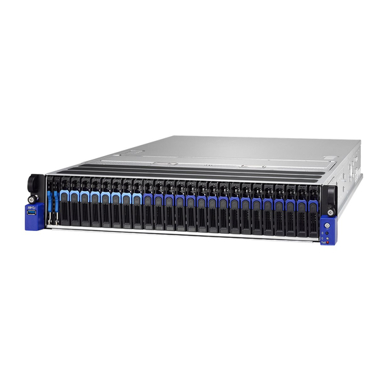
Page 29: About The Product
About the Product The following views show you the product. 1.5.1 System Front View http://www.tyan.com... - Page 30 Activity LED Status LED (Green color) (Orange color) Drive Present, Solid On No Activity Drive Present, Blinking with Activity Drive Fail Don’t care Solid On Drive identify Don’t care Blinking @ 1Hz Drive Rebuild Don’t care Blinking @ 4Hz http://www.tyan.com...
-
Page 31: System Rear View
SFP+1 (interface from mezzanine card) (FH) PCIE Gen3 Slot*3 SFP+2 (FH) PCIE Gen3 Slot*3 ID-LED (LP) PCIE Gen3 Slot*2 ID-LED Button PSU0 USB 3.0 port PSU1 RJ-45 Connector for IPMI VGA Port OCP v2.0 Mezzanine slot Serial Port USB 3.0 port http://www.tyan.com... - Page 32 AMBER deg (PMBus reading), or hot spot temperature>95deg (PMBus reading), high power, high current, slow fan(<1200rpm). AC present Only 12VSB on(PS off) or PS in Smart Blink Redundant state GREEN Output ON and OK AMBER AC cord unplugged http://www.tyan.com...
-
Page 33: Board Image
1.5.3 Board Image S8242 This picture is representative of the latest board revision available at the time of publishing. The board you receive may not look exactly like the above picture. http://www.tyan.com... -
Page 34: Block Diagram
1.5.4 Block Diagram http://www.tyan.com... -
Page 35: Motherboard Mechanical Drawing
1.5.5 Motherboard Mechanical Drawing http://www.tyan.com... -
Page 36: System Top View
1.5.6 System Top View http://www.tyan.com... - Page 37 Front Panel Bezel + M8242T76-L16-2F Riser (M1715T71-FPB pre-installed) Card pre-installed) Riser Card Bracket (M2093 (6) System Fan + M8242T76-R16-2F Riser Card pre-installed) Power Supply CPU0 Socket CPU1 Socket M2094 Riser Card Memory Slots NOTE: The system is pre-installed with S8242 mainboard. http://www.tyan.com...
-
Page 38: Chapter 2: Setting Up
Caution! To avoid damaging the motherboard and associated components, do not use torque force greater than 7kgf/cm (6.09 lb/in) on each mounting screw for motherboard installation. Do not apply power to the board if it has been damaged. http://www.tyan.com... -
Page 39: Precautions
Working on a system that is connected to a power supply can be extremely dangerous. Follow the guidelines below to avoid damage to TN76A-B8242 or injury to yourself. Ground yourself properly before removing the top cover of the system. -
Page 40: Installing Motherboard Components
CPU, heatsink, air duct, memory modules, HDD/SSD and LAN Card. 2.1.1 Removing the Chassis Cover Follow these instructions to remove the TN76A-B8242 chassis cover. Rotate the screw with a screwdriver counterclockwise to open the chassis cover and clockwise to close it. -
Page 41: Removing The Riser Card Brackets
2.1.2 Removing the Riser Card Brackets Follow these instructions to remove the PCI-E Riser Card Brackets. There are four PCIE brackets in the TN76A-B8242 chassis. Unscrew to release the PCI-E Riser Card Brackets. Lift up the Riser Card Brackets. http://www.tyan.com... - Page 42 Disconnect the Oculink cables. Disconnect the Oculink cables. http://www.tyan.com...
-
Page 43: Installing The Cpu, Heatsink
Note: The force frame will automatically eject after the captive screws are being released. By placing your both index fingers on the sides on the metal handle, pull to release the rail frame. Then lift the rail frame to its fully open position. Remove the external cap from the rail frame. http://www.tyan.com... - Page 44 During installation, observe the following: 1. Make sure to push the carrier frame with package towards the end of the rail frame until it clicks into place. 2. Do not drop the carrier frame or touch the package pad to avoid component damage. http://www.tyan.com...
- Page 45 7. Close the force frame. Then use a T20 Torx screwdriver to tighten the screws to secure the force frame in a sequential order (1 ->2->3). 8. To secure the heatsink, use a T30 Security Torx to tighten the screws. Tighten the four screws in a diagonal sequence to secure the heat sink. http://www.tyan.com...
-
Page 46: Installing The Memory
2. Align the memory module with the slot. When inserted properly, the memory slot locking levers lock automatically onto the indentations at the ends of the module. Follow the recommended memory population table to install the other memory modules. http://www.tyan.com... -
Page 47: Memory
2.1.5 Memory Memory population table http://www.tyan.com... - Page 48 Populating NVDIMMs NVDIMMs are identical only per channel pair. D-R,LR, or 3DS DIMM type Populating NVDIMMs capacity-2x D with capacity RDIMMs or LRDIMMs Table2.DIMM Interleaving Guidelines Slots DIMMs DIMM Frequency(MT/s) Populated 1.2V 2667 2667 2667 2400 2133 2133 2133 http://www.tyan.com...
- Page 49 √ √ P1_D1_UMC0_CH_A0 √ √ √ √ √ √ √ P1_D1_UMC0_CH_A1 √ P1_D1_UMC1_CH_B0 √ √ √ P1_D1_UMC1_CH_B1 √ √ √ √ √ P1_D0_UMC1_CH_C0 √ √ √ P1_D0_UMC1_CH_C1 √ √ √ √ √ P1_D0_UMC0_CH_D0 √ √ √ P1_D0_UMC0_CH_D1 √ √ http://www.tyan.com...
- Page 50 √ √ P1_D3_UMC0_CH_E0 √ √ √ √ √ P1_D3_UMC0_CH_E1 √ √ √ P1_D3_UMC1_CH_F0 √ √ √ P1_D3_UMC1_CH_F1 √ √ √ √ √ P1_D2_UMC1_CH_G0 √ √ √ √ √ √ P1_D2_UMC1_CH_G1 √ √ P1_D2_UMC0_CH_H0 √ √ P1_D2_UMC0_CH_H1 √ √ √ http://www.tyan.com...
-
Page 51: Installing Hard Drives
Follow these instructions to install hot-swap 2.5” 7/9mm SATA 6G hard drives and hot-swap 2.5” SATA 6Gb/s SSD/HDD. Warning!!! Always install the hard disk drive to the chassis after the chassis is secured on the rack. 2.5” 7/9mm SATA HDD Trays 1. Press down the latch to unlock the HDD trays. http://www.tyan.com... - Page 52 2. To pull the hard disk tray out. (Option 1: 2.5” SSD) Place a 2.5" hard drive into the SSD tray and stuck the SSD into the SSD tray. Reinsert the HDD tray into the chassis. http://www.tyan.com...
- Page 53 2.5” SATA 6Gb/s SSD/HDD 1. Press down the latch to unlock the HDD trays. 2. To pull the hard disk tray out. http://www.tyan.com...
- Page 54 3. Remove the 4 screws to detach HDD tray bracket. 4. Place a hard drive into the drive tray. Use four screws to secure the HDD. 5. Reinsert the HDD tray into the chassis. http://www.tyan.com...
- Page 55 6. Press the locking lever to lock the 2.5”SSD/ HDD tray. http://www.tyan.com...
-
Page 56: Rack Mounting
2.2.1 Installing the Server in a Rack NOTE: Before mounting the TYAN TN76A-B8242 in a rack, ensure that all internal components have been installed and that the unit has been fully tested. Screw Kit List Screw Size... -
Page 57: Installing The Inner Rails To The Chassis
Press the locking tab to draw out the inner rail from the rail assembly. Take out the rails and identify to pull the rail to the full length. Install the inner rail to the chassis. Repeat the same procedures for the other side. The installation of the inner rail is now complete. http://www.tyan.com... -
Page 58: Installing The Outer Rails To The Rack
Installing the Outer Rails to the Rack NOTE: Before mounting the TYAN TN76A-B8242 in a rack, ensure that all internal components have been installed and that the unit has been fully tested. However, to make the installation easier, we suggest that you remove all HDD trays before you insert the chassis to the rack. - Page 59 Slide the chassis back into the rack. Screw the chassis to the rack using 2pcs rotate screw. The installation is now complete. http://www.tyan.com...
-
Page 60: Chapter 3: Replacing Pre-Installed Components
M1293T76A-BP6-2 HDD Backplane Board, M8242T76-L16-2F/ M8242T76-R16-2F M7106-R24-3F/M7106-L24-3F riser card, M2094/M2093 NVMe riser card M1715T71-FPB Front Panel Board, M1714T71-USB Board, MP016T76-FB Fan Board, System Fan and Power Supply Unit etc. 3.0.2 Disassembly Flowchart The following flowchart outlines the disassembly procedures. http://www.tyan.com... - Page 61 http://www.tyan.com...
-
Page 62: Removing The Cover
Removing the Cover Before replacing any parts you must remove the chassis cover. Follow Section 2.1.1 Removing the Chassis Cover (page 40) to remove the cover of the TN76A-B8242. Replacing Motherboard Components Follow these instructions to replace motherboard components, including the motherboard. - Page 63 Unscrew the M2094 riser card to replace with a new one. http://www.tyan.com...
-
Page 64: Riser Card Features
PCIe x16 Slot x1 / PCIe x8 Slot x2 (1) S4P Power Connector M7106-R24-3F Riser Card Support (3) PCI-E Gen 3 Slots Specifications PCIe x1 Slot x1 / PCIe x16 Slot x1 / PCIe x8 Slot x2 (1) S4P Power Connector http://www.tyan.com... - Page 65 M2093 PCI-E OcuLink Card M2093 PCI-E OcuLink Card PCI-E x16 Gen3 slot interface Specifications (2) PCI-E x8 OcuLink connector M2094 PCI-E OcuLink Card M2094 PCI-E OcuLink Card PCI-E x24 Gen3 slot interface Specifications (3) Oculink Connector output http://www.tyan.com...
- Page 66 Uninstalling the M8242T76-L16-2F/M8242T76-R16-2F riser card Follow the same procedure to remove the M2093 NVMe riser card. Unscrew the M8242T76-L16-2F riser card to replace a new one if necessary. Unscrew to remove the M2093 NVMe riser card. http://www.tyan.com...
- Page 67 Unscrew the M8242T76-L16-2F riser card to replace with a new one. http://www.tyan.com...
-
Page 68: Pcie Riser Card Features
3.3.2 PCIE Riser card Features M8242T76-L16-2F riser card M8242T76-R16-2F riser card http://www.tyan.com... -
Page 69: Replacing The Fans
Replacing the Fans Follow these instructions to replace the fans. 1. Take out the fan module from the chassis. 2. Replace the failed fan module with a new one. 3. Loose the screws on both sides. http://www.tyan.com... - Page 70 4. Push the latch in the direction as the arrow shown to release the fan from the iron holder. 5. Remove the iron holder to replace a new fan. Follow the procedure reverse order to reinstall the system fan. http://www.tyan.com...
-
Page 71: Replacing The Fan Board
Replacing the Fan Board Follow these instructions to replace the MP016T76-FB Fan Board. Take out all the system fans. Remove the six screws. Lift the fan chassis up. http://www.tyan.com... - Page 72 Disconnect the fan cable and fan power cable. Take out the fan module and remove the 8 screws. http://www.tyan.com...
-
Page 73: Fan Board Features
Form Factor W389.5 x L54 (mm), 4-layer PCB (12) FAN Connector Specifications (2) Power Connector(J2/J5) (2) FAN Cable Connector(J1/J6) LEDs (12) Fan Fail LEDs 3.5.2 Fan Board LED Definition FAN Status Upper LED lower LED Normal On(Green) On(Green) Abnormal http://www.tyan.com... -
Page 74: Connector Pin Definitions
3.5.3 Connector Pin Definitions FAN Cable Connector (J1&J6) Definition Definition SYS_FAN1_TACH SYS_FAN6_TACH SYS_FAN2_TACH SYS_FAN7_TACH GSYS_FAN3_TACH SYS_FAN8_TACH SYS_FAN4_TACH SYS_FAN9_TACH SYS_FAN5_TACH SYS_FAN10_TACH PWM_SYS2 PWM_SYS1 SYS_FAN11_TACH SYS_FAN12_TACH VCC3_AUX PWM_SYS3 VCC3_AUX PWM_SYS4 PWM_SYS5 PWM_SYS6 FAN Connector (FAN1-FAN12) Definition Definition VDD_12V_RUN FAN_PWM TACH http://www.tyan.com... -
Page 75: Replacing The Hdd Backplane Board
Replacing the HDD Backplane Board Follow these instructions to replace the M1244T70A-BP12-8-B8026 M1293T76A-BP6-2 HDD Backplane Boards. M1244T70A-BP12-8-B8026 Pull all front HDD trays out. Disconnect the power cables and Mini-SAS HD cables. http://www.tyan.com... - Page 76 Loose the screws on the top side of the chassis. Loose the screws on both sides of the chassis. Loose screws on the chassis and take out the HDDs chassis to push the HDD backplane node. http://www.tyan.com...
- Page 77 There are three M1244T70A-BP12-8-B8026 backplane Boards installing on the chassis. Loose 6 screws to lift the mylar. Reinstall the HDD BP Board into the chassis following the steps in reverse. M1293T76A-BP6-2 Loose the screws on the top side of the chassis. http://www.tyan.com...
-
Page 78: Hdd Backplane Features
3.6.1 HDD Backplane Features Front View Rear View M1244T70A-BP6-8-B8026 HDD Backplane Board Form Factor 8-layer PCB (1) 8-pin Power Connector (PW3) (2) Mini-SAS Connector Integrated I/O (8) HDD Connector, 2.5” SAS/SATA 12Gb/s & hot-swap support http://www.tyan.com... - Page 79 Front view: Rear view: M1285T70A-BPE-8 HDD Backplane Board Form Factor 6-layer PCB, 76.8mm x 134.4mm (8) 2.5” hot-swap NVMe SSDs support (4) OcuLink connector Specifications (1) 2x4 pin power connector (1) SGPIO connector (1) CPLD JTAG connector http://www.tyan.com...
- Page 80 M1293T76A-BP6-2 Front View Rear View M1293T76A-BP6-2 HDD Backplane Board Form Factor 4-layers PCB (2) SATA Connector 0-1 Integrated I/O (2) HDD Connector 0-1 M1244T70A-BP6-8-B8026 HDD Backplane Board PW3: 8-pin Power Connector Definition Definition +12V +12V +12V +12V http://www.tyan.com...
-
Page 81: Replacing The Front Panel Board
Replacing the Front Panel Board Follow these instructions to replace the M1715T71-FPB Front Panel Board. Unscrew the front panel bezel. Take out the front panel bezel. Unscrew the Front Panel Board. http://www.tyan.com... - Page 82 Disconnect the Front Panel control cable. Reinstall the Front Panel Board into the chassis following the steps in reverse. http://www.tyan.com...
-
Page 83: Front Panel Board Features
Front Panel Board in details. Form Factor W37xL19xT1.6mm, 2-layer PCB (1) Front Panel Board Connector (J1) (1) Power Button with green color Power LED (J3) Specifications (1) ID Button (SW1) (1) blue color ID LED (LED_ID1) (1) orange color FAULT LED (LED_FAULT1) http://www.tyan.com... -
Page 84: Fpb Led And Connector Pin Definitions
Error occurred in the system Fault LED System works fine Green System powered on Power LED Blinking Green System standing by System AC off J1: Front Panel Board Connector Definition Definition FP_PW_LED_PW FP_PWR_BTN_N VCC_FPB FP_ID_LED_PW FP_PW_LED_GND FP_ID_LED_N FP_SMB_DAT BMC_HW_FAULT_N FP_SMB_CLK FP_IDLED_BTN_N BMC_SYS_FAULT_N http://www.tyan.com... -
Page 85: Replacing The Usb Board
Replacing the USB Board Follow these instructions to replace the M1714T71-USB USB Board. Unscrew 4 screws to release the USB board bezel. Take out the USB Board bezel. Disconnect the Front USB3.0 Cable. http://www.tyan.com... - Page 86 Unscrew the USB Board to replace with a new one. Reinstall the USB Board bracket into the chassis following the steps in reverse order. http://www.tyan.com...
-
Page 87: Disconnecting All Motherboard Cables
Disconnecting All Motherboard Cables Before replacing the motherboard or certain components, remove cables connected to the motherboard. Follow these instructions to remove all cables. Disconnect all cables. http://www.tyan.com... -
Page 88: Removing The Motherboard
3.10 Removing the Motherboard After removing all of the aforementioned cables, follow the instructions below to remove the motherboard from the chassis. Remove the nine screws securing the motherboard to the chassis. Carefully lift the motherboard from the chassis. http://www.tyan.com... -
Page 89: Replacing The Power Supply
The system has two pre-installed Power Supply Units. Please unplug the power cord before you follow these instructions to replace the power supply units. Press the latch to pull the power supply out. After replacing a new power supply, press the latch to push the power supply back into the chassis. http://www.tyan.com... -
Page 90: Chapter 4: Bios Setup
Select the previous value/setting of the field <+> Select the next value/setting of the field <F8> Load Fail Safe default configuration values of the menu <F3> Load the Optimal default configuration values of the menu <F4> Save and exit <Enter> Execute command or select submenu http://www.tyan.com... - Page 91 BIOS menus are continually changing due to continual BIOS updates over the product lifespan of the motherboard. The BIOS menus provided are current as of the date when this manual was written. Please visit TYAN’s website at http://www.tyan.com for information on BIOS updates available for this specific motherboard.
-
Page 92: Main Menu
It displays Platform information. Memory Information This displays the total memory size. System Language Choose the system default language. System Date Set the Date. Use Tab to switch between Date elements. Default Ranges: Year: 2005-2099 Months: 1-12 Days: dependent on month http://www.tyan.com... - Page 93 System Time Set the Time. Use Tab to switch between Time elements. http://www.tyan.com...
-
Page 94: Advanced Menu
CPU Configuration CPU Configuration parameters. Onboard Device Configuration Onboard Device and Function Configuration PCIE Slot Configuration Onboard PCIE Slot Configuraion Trusted Computing Trusted Computing Setting Hardware Health Configuration Hardware health Configuration S5 RTC Wake Settings S5 RTC Wake Settings http://www.tyan.com... - Page 95 PCI,PCI-X and PCI Express Settings USB Configuration USB Configuration Parameters. CSM Configuration CSM Configuration, Enable/Disable Option ROM execution setting,etc NVMe Configuration NVMe Device Options Settings SATA Configuration SATA Devices Information NVDIMM Force Self Refresh NVDIMM Force Self Refresh Configuration http://www.tyan.com...
- Page 96 4.3.1 CPU Configuration submenu SVM Mode Enable/disable CPU Virtualization Disabled / Enabled SMEE Control secure memory encryption enable Disabled / Enabled CPU 0 Information View Information related to CPU 0 CPU 1 Information View Information related to CPU 1 http://www.tyan.com...
- Page 97 4.3.1.1 CPU0 Information http://www.tyan.com...
- Page 98 4.3.1.2 CPU1 Information Read only. http://www.tyan.com...
- Page 99 Enabled / Disabled Active Video Select between onboard or external VGA support. Onboard Offboard Onboard LAN (Mellanox) Enable/Disable Onboard LAN Devices. Disabled Enabled NMI Button Enable or Disable NMI button Disabled Enabled Clock Spread Spectrum Enable/Disable CG1_PLL Spread Spectrum Disabled Enabled http://www.tyan.com...
- Page 100 NVMe / SATA SATA or NVMe link Select (J3-J4) Select link header function as NVMe or SATA function NVMe / SATA SATA or NVMe link Select (J5-J6) Select link header function as NVMe or SATA function NVMe / SATA http://www.tyan.com...
- Page 101 Setting PCIe Slot Link Width x4x4x4x4 / x8 / x16 PCIE Slot Option ROM Setting OCP Slot OPROM Enable/Disable load Option ROM For PCIe devices Enabled Disabled Riser 1 Up Slot OPROM Enable/Disable Load Option ROM For PCIe devices. Enabled Disabled http://www.tyan.com...
- Page 102 Auto / Gen 1 (2.5 GT/s) / Gen 2 (5 GT/s) / Gen 3 (8 GT/s) Riser 3 Middle Slot Link Speed Onboard PCIE Slot Link Speed Configuration Auto / Gen 1 (2.5 GT/s) / Gen 2 (5 GT/s) / Gen 3 (8 GT/s) http://www.tyan.com...
- Page 103 4.3.4 Trusted Computing Security Device Support Enable or disable BIOS support for security device. O.S. will not show Security device. O.S. will not show Security Device. TCG EFI protocol and INT1A interface will not be available. Enabled / Disabled http://www.tyan.com...
- Page 104 And BMC Alert Beep Item will appear. PWM Minimal Duty Cycle PWM Minimal Duty Cycle BMC Alert Beep Enable/Disable BMC Alert Beep On / Off PMBus Support PMBus Support Enabled / Disabled Number of PSU Number of PSU 1 / 1+1 / 2+1 http://www.tyan.com...
- Page 105 4.3.5.1 Sensor Data Register Monitoring When you enter the Sensor Data Register Monitoring submenu, you will see the following dialog window pop out. Please wait 8~10 seconds. NOTE 1: SDR can not be modified. Read only. http://www.tyan.com...
- Page 106 http://www.tyan.com...
- Page 107 Select 0-23. For example enter 3 for 3am and 15 for 3pm. Wake up minute Select 0-59 for Minute. Wake up second Select 0-59 for Second. When Wake system from S5 is set to [Dynamic Time] Wake up Minute increase 1-5. http://www.tyan.com...
- Page 108 NOTE: Console Redirection Settings menu only appear when Console Redirection was set to [Enabled]. Legacy Console Redirection Legacy Console Redirection Settings Serial Port for Out-Of-Band Management/Windows Emergency Services (EMS) Console Redirection Console redirection enable or disable. Disabled / Enabled http://www.tyan.com...
- Page 109 0 if the num of 1’s in the data bits is even. Odd: parity bit is 0 if the num of 1’s in the data bits is odd. Mark: parity bit is always 1. Space: parity bit is always 0. Mark and Space parity do not allow for error detection. None / Even / Odd / Mark / Space http://www.tyan.com...
- Page 110 Disabled / Enabled Legacy OS Redirection Resolution On Legacy OS, the number of rows and columns supported redirection. 80x24 / 80x25 Putty KeyPad Select FunctionKey and KeyPad on Putty. VT100 / LINUX / XTERMR6 / SCO / ESCN / VT400 http://www.tyan.com...
- Page 111 0 if the num of 1’s in the data bits is even. Odd: parity bit is 0 if the num of 1’s in the data bits is odd. Mark: parity bit is always 1. Space: parity bit is always 0. Mark and Space parity do not allow for error detection. None / Even / Odd / Mark / Space http://www.tyan.com...
- Page 112 With this mode enabled only text will be sent. This is to capture Terminal data. Disabled / Enabled Resolution 100x31 Enable or disable extended terminal resolution. Disabled / Enabled Putty KeyPad Select FunctionKey and KeyPad on Putty. VT100 / LINUX / XTERMR6 / SCO / ESCN / VT400 http://www.tyan.com...
- Page 113 When Bootloader is selected, then Legacy Console Redirection is disabled before booting to legacy OS. When Always Enable is selected, then Legacy Console Redirection is enabled for Legacy OS. Default setting for this option is set to Always Enable. Always Enable / BootLoader http://www.tyan.com...
- Page 114 VT-UTF8 / VT100 / VT100+ / ANSI Bits per Second Select serial port transmission speed. The speed must be matched on the other side. Long or noisy lines may require lower speeds. 115200 / 9600 / 19200 / 38400 / 57600 http://www.tyan.com...
- Page 115 ‘start’ signal can be sent to restart the flow. Hardware flow control uses two wires to send start/stop signal. None / Hardware RTS/CTS Data Bits / Parity / Stop Bits Read only. 4.3.8 AST2500 Super IO Configuration http://www.tyan.com...
- Page 116 / IO=3F8h, IRQ=3, 4, 5, 6, 7, 9, 10, 11, 12;DMA; / IO=2F8h; IRQ=3, 4, 5, 6, 7, 9, 10, 11, 12;DMA; / IO=3E8h, IRQ=3, 4, 5, 6, 7, 9, 10, 11, 12;DMA; / IO=2E8h, IRQ=3, 4, 5, 6, 7, 9, 10, 11, 12;DMA; http://www.tyan.com...
- Page 117 / IO=3F8h, IRQ=3, 4, 5, 6, 7, 9, 10, 11, 12;DMA; / IO=2F8h; IRQ=3, 4, 5, 6, 7, 9, 10, 11, 12;DMA; / IO=3E8h, IRQ=3, 4, 5, 6, 7, 9, 10, 11, 12;DMA; / IO=2E8h, IRQ=3, 4, 5, 6, 7, 9, 10, 11, 12;DMA; http://www.tyan.com...
- Page 118 If supported by hardware and set to ‘Enabled’, the Downstream Port disables its traditional Device Number field being 0 enforcement when turning a Type1 Configuration Request into a Type0 Configuration Request, permitting access to Extended Functions in an ARI Device immediately below the Port. Enabled / Disabled http://www.tyan.com...
- Page 119 Set Maximum Read Request Size of PCI Express Device or allow system BIOS to select the value Auto / 128 Bytes / 256 Bytes / 512 Bytes / 1024 Bytes / 2048 Bytes / 4096 Bytes MMIO Limit Address MMIO Limit Address 512 G / 1T / 2T / 4T / 255T http://www.tyan.com...
- Page 120 USB Mass Storage Driver Support Enable/Disable USB Mass Storage Driver Support Enabled / Disabled Port 60/64 Emulation Enables I/O port 60h/64h emulation support. This should be enabled for the complete USB keyboard legacy support for non-USB aware OSes. Enabled / Disabled http://www.tyan.com...
- Page 121 Controller. AUTO uses default value: for a Root port it is 100 ms, for a Hub port the delay is taken from Hub descriptor. Auto / Manual 4.3.11 CSM Configuration CSM support Enable/Disable CSM Support Enabled / Disabled Option ROM Messages Set display mode for Option ROM Force BIOS / Keep Current http://www.tyan.com...
- Page 122 Do not launch / UEFI / legacy Video Controls the execution of UEFI and legacy PXE OpROM Do not launch / UEFI / legacy Other PCI devices Determines OpRom execution policy for devices other than network, storage, or video legacy / UEFI 4.3.12 NVMe Configuration http://www.tyan.com...
- Page 123 4.3.13 SATA Configuration http://www.tyan.com...
- Page 124 4.3.14 NVDIMM Force Self Refresh Configuration Asset NVDIMM Save on Reset Asset NVDIMM Save on cold reset and warm reset Enabled / Disabled Asset NVDIMM Save on Shutdown Asset NVDIMM Save on Shutdown Enabled / Disabled http://www.tyan.com...
-
Page 125: Chipset Menu
Chipset Menu SMT Mode Simultaneous multithreading, OFF=1T single-thread Auto=2T two-thread if capable. Off / Auto Numa Enable or Disable Non uniform Memory Access (NUMA). Enabled / Disabled http://www.tyan.com... - Page 126 4.4.1 North Bridge Configuration Socket 0 Information View Information related to socket 0 Socket 1 Information View Information related to Socket 1 http://www.tyan.com...
- Page 127 4.4.1.1 Socket 0 Information http://www.tyan.com...
- Page 128 4.4.1.2 Socket 1 Information http://www.tyan.com...
- Page 129 Platform First Error Handling Enable/disable PFEH, cloak individual banks, and mask deferred error interrupts from each bank. Enabled / Disabled MCA Error Threshold Count MCA Error Threshold Count 0-Disable Error 0 / 1 / 5 / 10 / 100 / 1000 http://www.tyan.com...
-
Page 130: Amd Configuration
AMD Configuration http://www.tyan.com... - Page 131 SEV VMs using ASIDs below the SEV-ES ASIO Space Limit must enable the SEV-ES feature. The valid values for this field are from 0x1(1) – 0x10 (16) Streaming Stores Control Enables or disables the streaming stores functionality Disabled / Enabled / Auto http://www.tyan.com...
- Page 132 4.5.1.1 Core Thread Enablement http://www.tyan.com...
- Page 133 Sets the number of cores to be used. Once this option has been used to remove any cores, a POWER CYCLE is required in order for future selections to take effect. TWD (1+1) /TWD (2+0) / THREE (3+0) / FOUR (2+2) / FOUR (4+0) / SIX (3+3) Auto http://www.tyan.com...
- Page 134 4.5.1.2 Prefetcher settings L1 Stream HW Prefetcher Option to Enable / Disable L1 Stream HW Prefetcher Disable / Enable / Auto L2 Stream HW Prefetcher Option to Enable / Disable L1 Stream HW Prefetcher Disable / Enable / Auto http://www.tyan.com...
- Page 135 Controls the memory interleaving size. The valid values are AUTO, 256 bytes, 512 bytes, 1 Kbytes or 2K bytes. This determines the starting address of the interleave (bit 8,9,10 or 11). 256 Bytes / 512 Bytes / 1 KB / 2 KB / Auto http://www.tyan.com...
- Page 136 4.5.3 UMC Common Options http://www.tyan.com...
- Page 137 4.5.3.1 DDR4 Common Options http://www.tyan.com...
- Page 138 4.5.3.1.1 DRAM Timing Configuration http://www.tyan.com...
- Page 139 4.5.3.1.1.1 I Accept Configuration Overclock Memory Overclock settings Auto / Enabled http://www.tyan.com...
- Page 140 4.5.3.2 Common RAS Data Poisoning Enable/disable data poisning: UMC_CH:: EccCtrl [ UcFatalEn] UMC_CH:: EccCtrl [WrEccEn] should be enabled/disabled together. Disabled / Enabled / Auto http://www.tyan.com...
- Page 141 DRAM ECC Symbol Size DRAM ECC Symbol size (x4/x8) – UMC_CH:: EccCtrl [EccSymbolSize] Disabled / Enabled / Auto DRAM ECC Enable Use this option to enable / disable DRAM ECC. Auto will set ECC to enable. Disabled / Enabled / Auto http://www.tyan.com...
- Page 142 4.5.3.3 Security Data Scramble Data scrambling: DataScrambleEn Disabled / Enabled / Auto http://www.tyan.com...
- Page 143 Chipselect Interleaving Interleave memory blocks across the DRAM chip selects for node 0. Disabled / Auto BankGroupSwap This is an advanced performance setting, specifies if the system should use DRAM Bank Group swap mode. Disabled / Enabled / Auto http://www.tyan.com...
- Page 144 NBIO RAS Control Disabled / Enabled / Auto Determinism Slider Auto= Use default performance determinism settings Power Performance Auto / Power / Performance cTDP Control Auto = Use the fused cTDP Manual = User can set customized cTDP Manual / Auto http://www.tyan.com...
- Page 145 4.5.4.1 NB Configuration IOMMU Enable/Disable IOMMU Disabled / Enabled / Auto http://www.tyan.com...
- Page 146 4.5.5 FCH Common Options http://www.tyan.com...
- Page 147 4.5.5.1 AC Power Loss Options Restore Ac Power Loss Select Ac Loss Control Method Power Off / Power On / Last State http://www.tyan.com...
-
Page 148: Server Management
OS Watchdog Timer If enabled, starts a BIOS timer which can only be shut off by management Software after the OS loads. Helps determine that the OS successfully loaded or follows the OS Boot Watchdog Timer policy. Disabled / Enabled http://www.tyan.com... - Page 149 Not available if OS Boot Watchdog Timer is disabled. Do Nothing / Reset / Power Down / Power Cycle BMC Logo Enable or disable BMC logo Disabled / Enabled System Event Log Press<Enter> to change the SEL event log configuration. BMC network configuration Configure BMC network parameters http://www.tyan.com...
- Page 150 Choose options for reactions to a full SEL. Do Nothing / Erase Immediately Log EFI Status Codes Disable the logging of EFI Status Codes or log only error code or only progress code or both. Both / Disabled / Error Code / Progress Code http://www.tyan.com...
- Page 151 4.6.2 BMC Network Configuration http://www.tyan.com...
- Page 152 Select the configure LAN channel parameters statically or dynamically (by BIOS or BMC). Unspecified option will not modify any BMC network parameters during BIOS phase. Unspecified / Static / DynamicBmcDhcp Server Management Port2 IPV6 Support Enable or Disable LAN1 IPV6 Support Enabled / Disabled http://www.tyan.com...
-
Page 153: Security
Set user password in the Create New Password window. After you key in the password, the Confirm New Password window will pop out to ask for confirmation. Security Frozen Mode Enable or disable HDD security freeze lock. Disable to support secure erase function. http://www.tyan.com... - Page 154 Secure Boot activated when Platform Key(PK) is enrolled,system mode if 1.system running in User mode with enrolled platform Key(PK)2.CSM function is disabled Disabled / Enabled Secure Boot Mode Secure Boot mode selector: Standard/Custom. In Custom mode Secure Boot Variables can be configured without authentication Custom / Standard http://www.tyan.com...
- Page 155 Allow the image to run in Secure Boot mode. Enroll SHA256 hash of the binary into Autorized Signature Database (db) Save all Secure Boot variables Save NVRAM content of Secure Boot policy variables to the files(EFI_SIGNATURE_LIST data format) in root folder on a target file system device http://www.tyan.com...
- Page 156 3.EFI PE/COFF Image (SHA256) Key Source: Default, External, Mixed, Test Save to File / Set New / Erase Key Exchange Keys Enroll Factory Defaults or load certificates from a file: 1. Public Key Certificate in: a)EFI_signature_LIST b)EFI_CERT_X509 (DER encoded) c)EFI_CERT_RSA2048(bin) d)EFI_CERT_SHA256,384,512 http://www.tyan.com...
- Page 157 (DER encoded) c)EFI_CERT_RSA2048(bin) d)EFI_CERT_SHA256,384,512 2.Autheticated UEFI Variable 3.EFI PE/COFF Image (SHA256) Key Source: Default, External, Mixed, Test Set New / Append OsRecovery Signatures Enroll Factory Defaults or load certificates from a file: 1. Public Key Certificate in: http://www.tyan.com...
- Page 158 (DER encoded) c)EFI_CERT_RSA2048(bin) d)EFI_CERT_SHA256,384,512 2.Autheticated UEFI Variable 3.EFI PE/COFF Image (SHA256) Key Source: Default, External, Mixed, Test Set New / Append http://www.tyan.com...
-
Page 159: Boot
Wait For “ESC” If Error Enable or disable wait ‘ESC’ key Function. When chassis intrusion CMOS clear or BMC not Response. Disabled / Enabled Boot Option #1 Select the first boot device. Device Name / Device Name / Disabled http://www.tyan.com... - Page 160 Boot Option #2 Select the first boot device. Device Name / Device Name / Disabled 4.8.1 Delete Boot Option Configuration Delete Boot Option Remove an EFI boot option from the boot order Select one to Delete / Device Name http://www.tyan.com...
- Page 161 4.8.2 Network Device BBS Priorities Configuration Boot Option #1 Sets the system boot order. Device Name / Device Name / Disabled Boot Option #2 Sets the system boot order. Device Name / Device Name / Disabled http://www.tyan.com...
-
Page 162: Save & Exit
Reset system setup without saving any changes. Save Changes Save changes done so far to any of the setup options. Discard Changes Discard changes done so far to any of the setup options. Restore Defaults Restore/Load Default values for all the setup options. http://www.tyan.com... - Page 163 Save as User Defaults Save the changes done so far as User Defaults. Restore User Defaults Restore the User Defaults to all the setup options. http://www.tyan.com...
- Page 164 NOTE http://www.tyan.com...
-
Page 165: Chapter 5: Diagnostics
Please be aware that by flashing your BIOS, you agree that in the event of a BIOS flash failure, you must contact your dealer for a replacement BIOS. There are no exceptions. TYAN does not have a policy for replacing BIOS chips directly with end users. -
Page 166: Amibios Post Code (Aptio)
AP initialization before microcode loading 0x03 North Bridge initialization before microcode loading 0x04 South Bridge initialization before microcode loading 0x05 OEM initialization before microcode loading 0x06 Microcode loading 0x07 AP initialization after microcode loading 0x08 North Bridge initialization after microcode loading http://www.tyan.com... - Page 167 South Bridge initialization after microcode loading 0x0A OEM initialization after microcode loading 0x0B Cache initialization SEC Error Codes 0x0C – 0x0D Reserved for future AMI SEC error codes 0x0E Microcode not found 0x0F Microcode not found SEC Phase None PEI Phase http://www.tyan.com...
- Page 168 Memory initialization. Configuring memory 0x2F Memory initialization (other) 0x30 Reserved for ASL (see ASL Status Codes section below) 0x31 Memory Installed 0x32 CPU post-memory initialization is started. 0x33 CPU post-memory initialization. Cache initialization CPU post-memory initialization. Application Processor(s) (AP) 0x34 initialization http://www.tyan.com...
- Page 169 Unspecified memory initialization error 0x55 Memory not installed 0x56 Invalid CPU type or speed 0x57 CPU mismatch 0x58 CPU self test failed or possible CPU cache error 0x59 CPU microcode is not found or microcode update is failed. 0x5A Internal CPU error http://www.tyan.com...
- Page 170 Reserved for future AMI progress codes Recovery Error Codes 0xF8 Recovery PPI is not available. 0xF9 Recovery capsule is not found. 0xFA Invalid recovery capsule 0xFB – 0xFF Reserved for future AMI error codes PEI Beep Codes # of Beeps Description Progress Codes http://www.tyan.com...
- Page 171 North Bridge DXE initialization (North Bridge module specific) 0x6E North Bridge DXE initialization (North Bridge module specific) 0x6F North Bridge DXE initialization (North Bridge module specific) 0x70 South Bridge DXE initialization is started. 0x71 South Bridge DXE SMM initialization is started. http://www.tyan.com...
- Page 172 USB initialization is started. 0x9B USB Reset 0x9C USB Detect 0x9D USB Enable 0x9E -0x9F Reserved for future AMI codes 0xA0 IDE initialization is started 0xA1 IDE Reset 0xA2 IDE Detect 0xA3 IDE Enable 0xA4 SCSI initialization is started. http://www.tyan.com...
- Page 173 South Bridge initialization error 0xD3 Some of the Architectural Protocols are not available 0xD4 PCI resource allocation error. Out of Resources 0xD5 No Space for Legacy Option ROM 0xD6 No Console Output Devices are found. 0xD7 No Console Input Devices are found. http://www.tyan.com...
- Page 174 System is waking up from the S3 sleep state. 0x40 System is waking up from the S4 sleep state. System has transitioned into ACPI mode. Interrupt controller is in 0xAC APIC mode. System has transitioned into ACPI mode. Interrupt controller is in 0xAA APIC mode. http://www.tyan.com...
- Page 175 NOTE http://www.tyan.com...
-
Page 176: Appendix I: How To Recover Uefi Bios
UEFI recovery bootloader that would prevent the recovery process itself from working. In no event shall Tyan be liable for direct, indirect, incidental, special or consequential damages arising from the BIOS update or recovery. - Page 177 “Flash update completed. Press any key to reset the system” displayed on screen. Remove the USB disk and reboot. If your system does not have video output or the POST code halts at “FF” on the right-lower portion of the screen, please contact Tyan representatives for RMA service. http://www.tyan.com...
-
Page 178: Appendix Ii: Cable Connection Tables
M1293T76A-BP6-2 Connect to S8242 M/B → J1 (SATA cable) SATA3 → J2 (SATA cable) SATA4 → PWR11 (HDD BP PWR cable) 5. SW Cable SW cable to S8242 M/B SW cable Connect to S8242 M/B → SW cable J122 http://www.tyan.com... - Page 179 M2094 J3 (Oculink cable) → HDD BP3 J3 M2093 J1 (Oculink cable) (M8242-R16-2F) → HDD BP3 J4 M2093 J1 (Oculink cable) (M8242-R16-2F) → HDD BP3 PW1 MB PE_PW5 (HDD BP PWR cable) → HDD BP3 SGPIO1 MB J63 (SGPIO cable) http://www.tyan.com...
- Page 180 (HDD BP PWR cable) → M1244 HDD BP3 SAS_0 MB Mini-SAS HD J5 (Mini-SAS HD cable) → M1244 HDD BP3 SAS_1 MB Mini-SAS HD J6 (Mini-SAS HD cable) → M1244 HDD BP3 PW3 MB PE_PW5 (HDD BP PWR cable) http://www.tyan.com...
-
Page 181: Appendix Iii: Fru Parts Table
Appendix III: FRU Parts Table TN76A-B8242 FRU Parts Item Model Number Part Number Picture Description Power Supply FRU-PS-0080 471100000238 1200W PSU FAN module FRU-TS-0080 5412T4240001 FRU-TF-FAN MODULE Heatsink & Cooler FRU-TH-0290 343T58700001 Heatsink M7106-R24-3F Riser Card M7106-R24-3F 5411T5640007 (B8242T76AV26HR-2V SKU) - Page 182 422T57200007/ Oculink to Oculink Cable, 750mm FRU-CS-0690 422T57200001 (B8242T76AV2E24HR-2V SKU) Oculink to Oculink Cable (Reversed Signal), FRU-CS-0791/ 422T57100006/ 600mm FRU-CS-0700 422T57100004 (B8242T76AV2E24HR-2V SKU) FRU-CS-0330 332810000514 A/C Power Cord, L=1800mm, US type FRU-CS-0460 332810000515 A/C Power Cord, L=1830mm, EU type http://www.tyan.com...
-
Page 183: Appendix Iv: Fan And Temp Sensors
This section aims to help readers identify the locations of some specific FAN and Temp Sensors on the motherboard. A table of BIOS Temp sensor name explanation is also included for readers’ reference. NOTE: The red dot indicates the sensor. http://www.tyan.com... - Page 184 Fan Sensor: CPU0_FAN/CPU1_FAN. They detect the fan speed (rpm) Temp Sensor: SYS_Air_Outlet(U13), P0_SOC_MOSFET(RT3) P1_SOC_MOSFET(RT2). They detect the system temperature around. NOTE: is measured in a scale defined by Intel, not in Fahrenheit or CPU PECI Celsius. BIOS Temp Sensor Name Explanation: http://www.tyan.com...
- Page 185 http://www.tyan.com...
- Page 186 Fan speed of SYS_FAN_7 SYS_FAN_8 Fan speed of SYS_FAN_8 SYS_FAN_9 Fan speed of SYS_FAN_9 SYS_FAN_10 Fan speed of SYS_FAN_10 SYS_FAN_11 Fan speed of SYS_FAN_11 SYS_FAN_12 Fan speed of SYS_FAN_12 Fan speed of PSU1_FAN PSU1_FAN Fan speed of PSU2_FAN PSU2_FAN http://www.tyan.com...
-
Page 187: Appendix V: Installing Io Plate For Ocp Card
Follow these instructions to install the IO Plate for OCP Card. Here shows how to install the IO Plate for the dual-port LAN card M7106-X557-2T2E. Unscrew the riser card bracket. Remove the riser card bracket from the chassis. The chassis has pre-installed SFP+ bracket for the OCP card slot. Discharge the metal slug. http://www.tyan.com... - Page 188 Insert the LAN card into the OCP slot. Secure the LAN card to the chassis http://www.tyan.com...
-
Page 189: Appendix Vi: Technical Support
MiTAC serves multiple market segments with the industry’s most competitive services to support them. Please feel free to contact us directly for this service at tech-support@tyan.com Help Resources: 1. See the POST codes section of this manual. - Page 190 (RMA) number. The RMA number should be prominently displayed on the outside of the shipping carton and the package should be mailed prepaid. TYAN will pay to have the board shipped back to you. ® TN76A-B8242 Service Engineer’s Manual V1.0c...
Need help?
Do you have a question about the TN76A-B8242 and is the answer not in the manual?
Questions and answers