Table of Contents
Advertisement
Quick Links
OPERATION
MANUAL
Colormetry
CMU-324HE
For hardness
(For Overseas, excluding Europe)
This document was formulated in Japan. Comply
with the regulations and standards of the country of
use regarding installation and usage.
The specifications of products and components
may vary with country of use and the site situation.
INFORMATION IN THIS MANUAL MAY BE
CHANGED WITHOUT NOTICE.
Manual Code No.
S855-080-8710
Advertisement
Table of Contents

Related Manuals for Miura CMU-324HE


Summary of Contents for Miura CMU-324HE
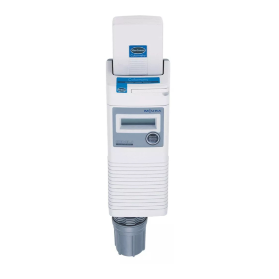
- Page 1 OPERATION MANUAL Colormetry CMU-324HE For hardness (For Overseas, excluding Europe) This document was formulated in Japan. Comply with the regulations and standards of the country of use regarding installation and usage. The specifications of products and components may vary with country of use and the site situation.
- Page 2 Release date: June 2018...
- Page 3 If any part used in the product fails, contact your dealer or MIURA sales office to have it replaced with a genuine part. Using parts with other model numbers may reduce the safety.
-
Page 4: Introduction
Introduction Introduction This document describes the methods of handling the Colormetry CMU-324HE (hereinafter called “the device”) to ensure its proper use. Not only those who use the device for the first time but also those who know the handling methods should read this document carefully and understand the proper handling methods before use of the device. -
Page 5: Definition Of Terms
Definition of Terms Definition of Terms Special terms used in this document are summarized below. Learn the terms and their meanings. (Terms are indicated with an asterisk (*) in the text.) Term Explanation A type of output method in electronic circuits. (The transistor collector is Open collector located outside the circuit, and a load is connected to it.) A part that is present inside the cell and is used to mix the reagent and... -
Page 6: Table Of Contents
Table of Contents Table of Contents Important Safety Information ..............i Introduction .................... ii Definition of Terms ................iii SECTION 1: SAFETY ................. 1 1. Safety Regulations ................... 1 2. Safety-related Knowledge and Expertise ..........3 3. Protective Equipment ................3 4. - Page 7 Table of Contents 3.3 Monitoring Capabilities ..................20 3.4 Feed Water Tube and Drain Tube Connection ..........21 3.5 Accessories ...................... 22 3.6 Consumables (Sold Separately) ............... 22 SECTION 3: PRE-OPERATION INSPECTION ........ 23 1. Inspections and Preparations before Startup ......... 23 1.1 Inspection and Preparation of the Peripheral Equipment ........
- Page 8 Table of Contents 3. Daily Inspection ..................44 3.1 Inspection Item ....................44 3.1.1 Checking Automatic Monitoring ..............44 3.1.2 Checking Feed Water Tube and Drain Tube .......... 44 3.1.3 Checking Filter Casing Assembly ............. 45 3.2 Others ....................... 45 SECTION 6: TROUBLESHOOTING ..........
-
Page 9: Section 1: Safety
3) The documents to be submitted and their destination vary depending on your equipment and facilities. If you have any questions, contact your nearest dealer, MIURA sales office, or the competent supervisory authority. 4) The laws and regulations listed below may not apply to all water treatment equipment. Refer only to those laws and regulations that apply to your equipment and facilities. - Page 10 2) This table shows the laws and regulations as of the end of September 2017. For the most up-to-date information, contact the competent administrative authority. 3) The management and handling differ depending on the chemicals you handle. If you have any questions, contact your nearest dealer, MIURA sales office, or the competent administrative authority. Common Submission...
-
Page 11: Safety-Related Knowledge And Expertise
4. Prohibition of Unapproved Modification It should be noted that unauthorized alteration of the device or repair procedures other than those described herein can pose a serious safety risk. Never make any modifications or repairs without MIURA’s permission. -
Page 12: Warning Labels On The Device
Warning labels are pasted at all locations that require attention to be paid during operation. If any warning label is peeled off or torn, replace it with a new one. For further details on warning labels contact your dealer or MIURA sales office. Side and rear of reagent cartridge... -
Page 13: Safety Precautions
SECTION 1: SAFETY 6. Safety Precautions 6.1 Safety during Installation During installation, observe the following safety information. Ensure that drain piping is fixed securely in place to prevent it from moving in reaction to drain discharge and that the end of the piping opens in a safe location such as a pit. -
Page 14: Safety During Operation
Make sure the main power circuit breaker is turned OFF and contact your dealer or MIURA sales office. Do not place anything which may cause electric leakage underneath the device. The device is designed to drain water from the bottom of the device if there is inner water leakage due to the increase in pressure, etc. -
Page 15: Safety During Inspection And Maintenance (Excerpt From Page 39 Onwards)
Also, make sure the earth leakage circuit breaker is turned OFF and a main feed water valve is closed and contact your dealer or MIURA sales office. Failure to observe this precaution may lead to electric shock, fire, or device failure. -
Page 16: Safety During Storage (Excerpt From Page 48 Onwards)
SECTION 1: SAFETY If there is a defect or cracking on the filter casing assembly, turn OFF the earth leakage circuit breaker and close a main feed water valve before replacing the filter casing assembly. If water leakage is not stopped even though the filter casing assembly and tube joint are tightened, replace the filter casing assembly. -
Page 17: Section 2: Overview
1.2 Purpose The Colormetry CMU-324HE is a device for monitoring water quality. It is not a device for measuring. The result data cannot be used for inspection or analysis of the water treatment system. -
Page 18: System Layout
SECTION 2: OVERVIEW 1.3 System Layout The Colormetry consists of the reagent cartridge (the indicator), reagent indicator mechanism, monitoring system, and feed water and drain systems. Colormetry layout Reagent cartridge Reagent injection Solenoid valve P pump Regent injection system Constant Nozzle Tube flow valve... -
Page 19: Principle
SECTION 2: OVERVIEW 1.4 Principle The Colormetry is a device to monitor ionic concentrations in water by applying colorimetric analysis. In a colorimetric analysis process the ionic and other concentrations in water are monitored by allowing a reagent to react against the target ions and others, and monitoring the transmissivity of the resultant coloration for light of a specific wavelength. -
Page 20: Applicable Water Condition
SECTION 2: OVERVIEW 1.5 Applicable Water Condition The Colormetry CMU-324HE monitors the hardness. Use CMU-H2 reagent cartridge. The reagent may be affected by substances other than hardness The device cannot measure water of the condensate recovery tank. Keep to the following items in an allowable range. If the water condition is not followed, the device may fail to monitor correctly. -
Page 21: Highlights Of Features
SECTION 2: OVERVIEW 1.6 Highlights of Features The Colormetry has the following features: [1] Monitors hardness leakage automatically • The monitoring process is fully automated, saving a significant amount of work by eliminating the need for complicated manual procedures. [2] Requires no periodic calibration •... - Page 22 SECTION 2: OVERVIEW [9] Requires minimal maintenance • The reagent cartridge can be replaced using a one-touch action. The reagent cartridge needs no replacement for approximately 4 months in typical applications. (Note that more frequent replacement may be necessary, depending on the application.) [10] Compact in design, easy to install •...
- Page 23 SECTION 2: OVERVIEW [12] Data collection tool Up to 10,000 monitoring records (monitoring date and time, and monitoring results) can be stored in the Colormetry. Also, by using a dedicated data collection tool installed on the , the monitoring record data can be transferred to the PC. However, the Colormetry and PC must be connected by an RS-232C cable *1: Data for almost 1 year can be stored when monitoring at an interval of 60 minutes.
-
Page 24: Name Of Parts
SECTION 2: OVERVIEW 2. Name of Parts 2.1 Overall View Reagent cartridge Cartridge lever LCD display Reagent cartridge replacement notification LED Manual Monitor switch (Buzzer Stop switch) Device alarm/ hardness leakage alarm LED Maintenance cover Maintenance cover fixing screws Filter casing assembly... - Page 25 SECTION 2: OVERVIEW 125(5inch) 100(4inch) 45(1 inch) 95(3 inch) 25(1inch) 75(3inch)dia inch) 50(2inch)
-
Page 26: Reagent Cartridge
SECTION 2: OVERVIEW 2.2 Reagent Cartridge Tube Check D-ring tube Reagent injection nozzle... -
Page 27: Filter Casing Assembly
SECTION 2: OVERVIEW 2.3 Filter Casing Assembly Filter casing assembly O-ring Constant flow valve (the black rubber plate Tube joint φ6 installed on the end) Filter casing Filter casing (top) (bottom) O-ring Fiber filter... -
Page 28: Specifications
SECTION 2: OVERVIEW 3. Specifications 3.1 General Specifications (*1 and *2) Power supply voltage 24 VAC (±10%) Rated power consumption 15 W (on operation) Ambient operating temperature 5–50°C (41–122°F) range Raw water temperature range 5–40°C (41–104°F) Humidity range 20–90% RH (no condensation and freezing) Raw water pressure range 0.05–0.49 MPa (7.2–71 psi) -
Page 29: Feed Water Tube And Drain Tube Connection
If a deteriorated tube is continuously used, it can rip and cause water leakage. Make a daily check on whether the tubes are in normal condition. Use specified tubes when replacing tubes. Using tubes other than specified tubes may cause leakage. Contact your dealer or MIURA sales office. -
Page 30: Accessories
SECTION 2: OVERVIEW 3.5 Accessories • Feed water tube (φ6 mm) • Drain tube (φ8 mm) • Fiber filter • Filter casing assembly • Ball valve and piping parts • Wall-mounting bracket and installation parts • Operation Manual • AC adapter (provided with the product only for North America) 3.6 Consumables (Sold Separately) •... -
Page 31: Section 3: Pre-Operation Inspection
Make sure no water is leaking from the device and from around the piping. • Do not start the operation if leakage is found. Instead, ensure that the main power breaker is set to the OFF position, and then contact your dealer or MIURA sales office. NOTE... -
Page 32: Preparations Before Startup
SECTION 3: PRE-OPERATION INSPECTION 2. Preparations before Startup CAUTION Do not place anything which may cause electric leakage underneath the device. The device is designed to drain water from the bottom of the device if there is inner water leakage due to the increase in pressure, etc. Water may splash to the item under the device. -
Page 33: Section 4: Operation
SECTION 4: OPERATION SECTION 4: OPERATION 1. Operation 1.1 Device State Check When the power of the device is turned on, the device state check starts automatically. • If the device is working correctly, the check process completes in about 2 to 12 minutes. (The check process time varies depending on the model, instantaneous flow rate, and concentration of sample water.) •... -
Page 34: Automatic Monitoring
SECTION 4: OPERATION 1.2 Automatic Monitoring When the set time of the monitoring interval has passed, monitoring starts. The monitoring start timing is also controlled by the remote signal. * If the monitoring stop time passed during monitoring, the device enters the standby mode as soon as the monitoring is completed. -
Page 35: Functions
SECTION 4: OPERATION 2. Functions 2.1 Remote Signal Input 2.1.1 Method Monitoring the stagnant water in the piping may result in a concentration alarm or device alarm due to the lack of flow. To avoid such alarms, the Colormetry provides the following two methods, which can be used simultaneously. - Page 36 SECTION 4: OPERATION [2] Monitoring is enabled when the remote signal is ON [S Rte Sgl On] The ON state of the remote signal (the external contact closes) permits scheduled monitoring after the monitoring interval [S Intvl]. Example 2-1: Inputting service signals of the water softener or other filtration equipment When remote signals are input from a water softener...
-
Page 37: Delay Time Of Remote Signals
SECTION 4: OPERATION 2.1.3 Delay Time of Remote Signals The purpose of remote signal delay time [S DelayTime]: The setting determines the number of seconds the monitoring is to be delayed after receiving the remote signal. It is not commonly used function, however it is effective to prevent an evaluation error in the example case shown below. -
Page 38: Colormetry Monitoring Timing
SECTION 4: OPERATION 2.2 Colormetry Monitoring Timing 2.2.1 Automatic Monitoring The interval between monitoring is set in the monitor interval [S Intvl] setting at the setting mode [Set Mode] (The interval is selectable in 30minutes increments between the 30 to 240 minutes range). - Page 39 SECTION 4: OPERATION b. If the remote signal setting is for “monitoring is enabled by remote signal being turned ON” [S Rte Sgl On]: (Example of remote signal: Service signal from the water softener • When the preset time of the monitor interval [S Intvl] has passed, if the remote signal is ON, the remote signal delay time S Rte Sgl dl[] will start.
-
Page 40: Manual Monitoring
SECTION 4: OPERATION [3] With monitor start time [S Start] and stop time [S Stop] are set up a. When the preset time of the monitor interval [S Intvl] has passed, but not monitor start time [S Start] yet, the Colormetry keeps in standby until the monitor start time. When the monitor start time came, the preset remote signal delay time will start and monitoring will start soon after the remote signal delay time is finished. -
Page 41: Concentration Evaluation
SECTION 4: OPERATION 2.3 Concentration Evaluation The Colormetry evaluates ionic concentrations in 5 levels: 0 mg/L, 1 mg/L, 2 mg/L, 3 mg/L, and 5 mg/L. Alarm set point may be set to trigger at 1 mg/L and up, 2 mg/L and up, 3 mg/L and up, and 5 mg/L and up. -
Page 42: Concentration Anomaly
SECTION 4: OPERATION 2.3.2 Concentration Anomaly [1] If an evaluation result is the alarm set point [S AlarmSet] and up, monitoring is repeated the number of times as set (between 1 to 3) in the concentration alarm retry [S Alarm Inc No] setting. - Page 43 SECTION 4: OPERATION [3] If a concentration anomaly occurs repeatedly in a series of automatic monitoring at the monitor interval [S Intvl], or in manual monitoring, the concentration anomaly alarm will stay on continuously. [4] The concentration anomaly alarm is automatically terminated (the buzzer stops and the remote alarm output contact opens) upon that the condition is determined normal in automatic monitoring at the monitor interval [S Intvl], or in manual monitoring.
- Page 44 SECTION 4: OPERATION Monitoring example 2: (Concentration alarm retry [S Alarm Inc No] setting: 3 Concentration alarm judgment [S Alarm Det No] setting: 1) Monitoring interval Monitoring interval Monitoring interval [S Intvl] [S Intvl] [S Intvl] Concentration alarm Concentration alarm is reset occurs Condition is evaluated...
- Page 45 SECTION 4: OPERATION 2.3.2.1 Display on Evaluation Result Result: 2mg/L Hardness Leakage Switching automatically *1: The sample display represents an evaluation exceeding 2mg/L 2.3.2.2 Output on Concentration Alarm a. When a concentration alarm occurs, the buzzer sounds. If the remote alarm output type is NC, the remote alarm output signal turns OFF.
- Page 46 SECTION 4: OPERATION 2.3.2.3 Workings of Hardness Leakage Alarm and Action to Take Hardness leakage alarm occurs Buzzer starts sounding Remote alarm output ON Concentration alarm output ON “Manual Monitor” switch is pressed Buzzer sounds Buzzer stops Evaluation result is displayed [1] The buzzer sounds for a concentration anomaly.
-
Page 47: Section 5: Inspection And Maintenance
During the self-diagnosis, if “New Cartridge” is displayed, the remained volume of reagent is low and the evaluation error might occurs. For the new reagent cartridge, contact your dealer or MIURA sales office. 1.2 Cautions for Handling Never disassemble the reagent cartridge. -
Page 48: Reagent Cartridge Replacement Method
SECTION 5: INSPECTION AND MAINTENANCE 1.3 Reagent Cartridge Replacement Method NOTE • Replace the reagent cartridge while the power is supplied to the device. Close the sample water collecting ball valve and replace while monitoring standby period. • When install the reagent cartridge, attach the D-ring first. To install D-ring to the reagent cartridge, dip the D-ring into water. -
Page 49: Fiber Filter And Constant Flow Valve Replacement
SECTION 5: INSPECTION AND MAINTENANCE 2. Fiber Filter and Constant Flow Valve Replacement 2.1 Fiber Filter Replacement Timing Do not place anything which may cause electric leakage underneath the device. When replacing the fiber filter , water may spill around the device and splash to the item under the device. -
Page 50: Replacing Fiber Filter
SECTION 5: INSPECTION AND MAINTENANCE 2.2.2 Replacing Fiber Filter 1) The filter casing assembly comes apart into two sections. Rotate the top and bottom sections in a counterclockwise direction to take them apart, and remove the fiber filter 2) Insert the tip end of the fiber filter into the center of the filter casing (top). -
Page 51: Installing Filter Casing Assembly
SECTION 5: INSPECTION AND MAINTENANCE 2.2.3 Installing Filter Casing Assembly CAUTION Do not apply grease or lubricant when installing the filter casing assembly. It may damage the material of the device and cause water leakage. NOTE When you install the filter casing assembly, simply screw it in by hand. Do not use any kind of fitting tool. -
Page 52: Daily Inspection
Also, make sure the earth leakage circuit breaker is turned OFF and a main feed water valve is closed and contact your dealer or MIURA sales office. Failure to observe this precaution may lead to electric shock, fire, or device failure. -
Page 53: Checking Filter Casing Assembly
SECTION 5: INSPECTION AND MAINTENANCE 3.1.3 Checking Filter Casing Assembly If there is a defect or cracking on the filter casing assembly, turn OFF the earth leakage circuit breaker and close a main feed water valve before replacing the filter casing assembly. If water leakage is not stopped even though the filter casing assembly and tube joint are tightened, replace the filter casing assembly. -
Page 54: Section 6: Troubleshooting
1.1 Display If an alarm occurs as a result of the self-diagnosis, the major cause is displayed in the LCD. If you cannot handle, contact your dealer or MIURA sales office as soon as possible. 1.2 Alarm Alarm occurs as a result of... -
Page 55: Self-Diagnosis Items
The amount of reagent injected from the Replace the reagent cartridge. Injection F F281 reagent cartridge is insufficient. Temperature sensor for sample water Contact your dealer or MIURA Thmsta F :C131 detection (thermistor ) has failed or is sales office. -
Page 56: Section 7: Storage
SECTION 7: STORAGE SECTION 7: STORAGE 1. Extended Inactivity If the device is to be inactive for an extended period of time, contact your dealer or MIURA sales office. NOTE If the device will not be used for an extended period of time (more than a week), it should be stored properly. -
Page 57: Section 8: Disposal
SECTION 8: DISPOSAL SECTION 8: DISPOSAL 1. Disposal When disposing of the product, comply with the laws and regulations. -
Page 58: Section 9: Warranty
SECTION 9: WARRANTY 1. Note Regarding Warranty Regarding the contents of the warranty, contact your dealer or MIURA sales office. 2. Questions Regarding the Product and Operation Manual For any questions about your purchased product or the content of this Operation Manual, contact your dealer or MIURA sales office.
Need help?
Do you have a question about the CMU-324HE and is the answer not in the manual?
Questions and answers