Advertisement
Table of Contents
- 1 Technical Specifications
- 2 Unpacking and Testing the Tripod Turnstile
- 3 Equipment Installation
- 4 Cable Diagram
- 5 Equipment Precautions and Maintenance
- 6 Troubleshooting
- 7 Attachment 1 Default Factory Settings
- 8 Attachment 2 Connection Diagram of Control Board and Access Control Panel
- Download this manual
Advertisement
Table of Contents

Related Manuals for ZKTeco TS1000 Series


Summary of Contents for ZKTeco TS1000 Series
- Page 1 TS1000 Series Vertical Tripod Turnstile User Manual Version: 2.4 Date: Jan, 2018...
-
Page 2: Technical Specifications
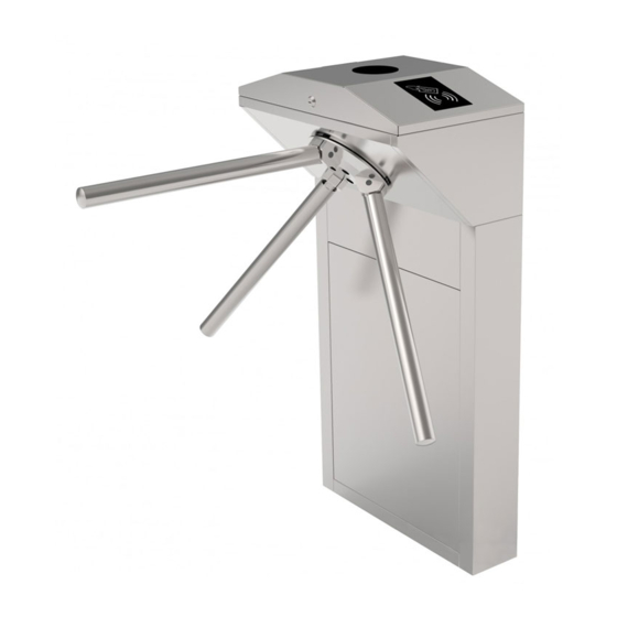
TS1000: Tripod Turnstile TS1011: Tripod Turnstile with Controller and RFID Reader TS1022: Tripod Turnstile with Controller and Fingerprint Reader with RFID function. Please read this document carefully before installation and using the device. 1. Technical Specifications AC 100~120V /200~240V, Center: 80 kg Input Voltage Max. - Page 3 2.2 Arm installation method Installation procedure 1. Using the glue and applying in the hole of the arms as well as the one countersunk screw, as shown in Figure 2-2. (This is to prevent screws from getting loose due to vibration after being used for a long time.) 2.
-
Page 4: Equipment Installation
3. Equipment Installation 3.1 Installation conditions The equipment must be installed on concrete ground, ensuring that expansion bolts can be secured firmly. You are suggested to install an assistant framework or fence to form a passageway, as shown in Figure 3-1. >100 <80 <80... - Page 5 Figure 3-3 3.3 Installation Drilling holes. Drill holes based on the locations of the holes shown in Figure 3-3. Fix the mounting plate to its original position. Placing the mounting plate properly and apply screw securing glue on the surface and the threads of the expansion bolts, install four expansion bolts to secure the mounting plate, and use a horizontal ruler to test the levelness of the mounting plate.
-
Page 6: Cable Diagram
4. Cable Diagram 4.1 Function description of the turnstile control board If you are using TS1011 or TS1022, all the connections between access control and turnstile control boards are done in factory. Just plug in communication cable to access controller and do the setting. If you are using TS1000, you need to connect access control system to the control board, please check the content in this chapter carefully. - Page 7 J6 Drop Arm: Short circuit DOW and GND, the arm is dropped down by force in case there are fires or other emergencies. J8 Proximity Switch Signal Input: Input position signal of the arm. J9 12V Power Supply for Access control: control board directly provide Access Control with 12V power. (Maximum support 3A) V1L Left Solenoid, V2R Right Solenoid &...
-
Page 8: Equipment Precautions And Maintenance
4.3.2 Direction indicator It is to indicate whether the passage allows people to pass. The green arrow means passing is allowed while the red "X" means passing is prohibited. The indicator status can be set through number 4 and 5 in the DIP switch. The description of the bit settings are as follows: 11 = One-way traffic, left passing is allowed. - Page 9 The maximum tolerance of the tripod turnstile's arms Please note that the maximum stress tolerance at the center of the arm is 80kg and at the ends of the arm is 40kg (See Figure 5-1).When the impact force on the tripod turnstile reaches the designed limit, the arms break down first to ensure that the whole equipment is not damaged and the passer-by is not injured.
-
Page 10: Troubleshooting
6. Troubleshooting Symptom Troubleshooting It may be caused by the power supply or circuit. The indicator is not lighted when the Check whether the connection cable and power cable between are equipment is powered on. damaged, or the wiring is loose. It may be caused by the problem of relative components or drop-arm solenoid. -
Page 11: Attachment 1 Default Factory Settings
Figure 6-1 Normal status of the drop-arm solenoid Normal status (closed) of the drop-arm after being powered off solenoid after being powered on. Figure 6-2 Attachment 1 Default Factory Settings Function Default Lock Driving Duration Door Sensor None Verification Interval Controller Communication TCP/IP: 192.168.1.201 Turnstile Opening Duration... -
Page 12: Attachment 2 Connection Diagram Of Control Board And Access Control Panel
Attachment 2 Connection Diagram of Control board and Access Control Panel Warning: This is a class A product. In a domestic environment this product may cause radio interference in which case the user may be required to take adequate measures.
Need help?
Do you have a question about the TS1000 Series and is the answer not in the manual?
Questions and answers