
Summary of Contents for Mission RGO ONE
- Page 1 Revision 1.00 beta – April 2019 RGO ONE Short wave amateur transceiver Operating manual...
-
Page 2: Table Of Contents
Revision 1.00 beta – April 2019 TABLE OF CONTENTS 1. Introduction…………………………………………………………………… 2. Specifications…………………………………………………………………. 3. Before operation……………………………………………………………… 3.1. Front panel controls…………………………………………………. 3.2. Rear panel view………………………………………………………. 4. Installation…………………………………………………………………….. 4.1. General…………………………………………………………………. 9 4.2. Connections……………………………………………………………. 4.2.1. Power requirements……………………………………………. 4.2.2. Antenna………………………………………………………….. 5. Controls and Periphery……………………………………………………….. 5.1. -
Page 3: Introduction
Revision 1.00 beta – April 2019 1. Introduction RGO ONE is classic superheterodyne down conversion HAM transceiver covering all HF bands 1.8 - 29.7MHz (160/60m as an option). Due to its modular construction it can be easily modified or redesigned in manner that suits operator. This kit is intended for users that like building their own home made equipment and constructions. -
Page 4: Specifications
Revision 1.00 beta – April 2019 2. Specifications Test conditions: Supply voltage 13.8V, temperature 20C, antenna output terminated with 50ohm dummy load General: Size: Cabinet: H 80mm; W 200mm; D 194mm (H 3.2”; W 7.9”; D 7.6”) Overall: H 90mm; W 200mm; D268mm (H 3.5”; W 7.9”; D 10.6”) (including optional fan cradle) Weight 2.670kg (5.9lbs.) (including optional fan cradle and weighted... - Page 5 Revision 1.00 beta – April 2019 4 common lines Polarizer type – transflective USB UART interface FTDI chipset. Speed 9600 - 56300bps Receiver Sensitivity (MDS) -135dBm (preamplifier On; VBF filter 2) -129dBm (preamplifier Off; VBF filter 2) Selectivity Crystal 8 pole 2.7kHz first roofing filter at 9MHz 0.2-2.7kHz second variable filter Johnson type 9MHz Crystal 2-pole IF noise filter 9MHz Dynamic range...
- Page 6 USB keying via DTR and RTS lines (on/off in menu ) Speed range 5 – 45 WPM CW memory 4 locations 128 bytes each; CW beacon function *Performance of RGO ONE transceiver degrades significantly outside HAM bands although reception and tuning is continuous.
-
Page 7: Before Operation
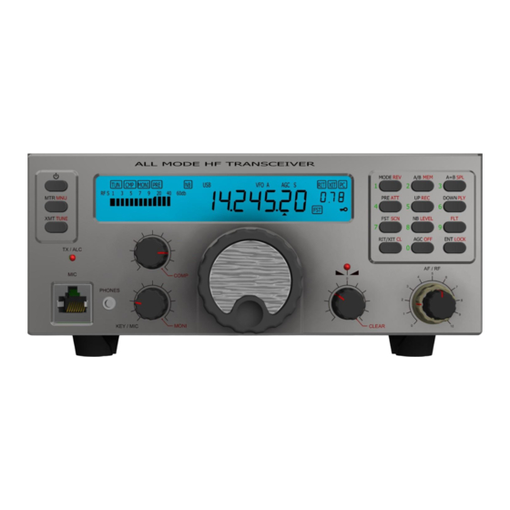
Revision 1.00 beta – April 2019 3. Before operation 3.1. Front panel controls RGO ONE transceiver is operated by 15 buttons, three mechanical encoders, main dial optical encoder, one dual concentric potentiometer AF/RF (10kohm/logarithmic + 10kohm/linear). The equipment has large custom multicolor backlit FSTN liquid crystal display (LCD)and two red LEDs, so various parameters like frequency, modes, signal strength and others can be displayed. -
Page 8: Rear Panel View
Revision 1.00 beta – April 2019 3.2. Rear panel view The rear panel consist of power supply Anderson power pole connector, SO-239 antenna connector and other interface connectors. Rear panel is shown on fig.2 fig.2 1. Antenna socket – SO239 2. -
Page 9: Installation
4.2. Connections 4.2.1. Power requirements Stabilized power supply of 12-14V DC capable of supplying 12A, negative ground is required. Battery operation: RGO ONE can work on battery, when the voltage does not fall bellow 11V. 4.2.2. Antenna Any matched 50 ohm unbalanced antenna can be used with RGO ONE. Antennas... -
Page 10: Controls And Periphery
Any type (4 - 32 ohm) stereo phones with 3.5mm jack can be used 5.4. External speaker – rear panel RGO ONE has internally built in speaker 8ohm/5W but external speaker can be connected also via “SP” jack on the rear panel. -
Page 11: Acc1 - Accessory Connector
Revision 1.00 beta – April 2019 5.5. ACC1 - accessory connector – rear panel Fig.6 Pins: 1 – 13V 2 – VC. Front panel supply voltage 3 – 6 Not in use 7 – CWK signal – CW keying from external source (PC) 8 –... - Page 12 Revision 1.00 beta – April 2019 TX – Indicates transmit mode TUN – Tunning procedure is initiated or optional tuner is presently working CMP – Optinal SSB compressor unit is activated MONI – Monitoring own signal on transmit. Can be activated with CW/phone modes PRE –...
-
Page 13: Front Panel Buttons
Revision 1.00 beta – April 2019 5.7. Front Panel buttons RGO ONE has two keyboards: Left of display for on/off, menu and tune buttons; Right of LCD is situated numeric keypad Buttons designations have three colors: Black – The function is activated with short press of a button Red –... -
Page 14: Encoder Functions And Buttons
Revision 1.00 beta – April 2019 DOWN PLY - Short press changes frequency to the next lower band in VFO and to the next lower memory location in memory mode; Long press starts CW memory play. FST SCAN – Short press toggles between steps 1Hz-10Hz-100Hz-1kHz. FST icon lights up when 100Hz and 1kHz steps are selected;... - Page 15 Revision 1.00 beta – April 2019 Short press toggles between MIC gain and KEYER speed Long press sets monitor level control both for CW/phone modes Encoder 3 RIT/XIT Adjusts RIT/XIT value (shown on sub display) Scrolls functions in MENU mode Scrolls channel in MEMORY mode Button short press: When in MENU discards changes made and leaves the menu...
-
Page 16: Menu Structure
Revision 1.00 beta – April 2019 6. MENU structure Long press of MTR MNU button enters configuration menu. Long press of MTR MNU button stores parameters changed and leaves the menu Short press of a RIT/XIT CL button discards changes made and leaves menu Fig.8 Function selection is controlled by rotating of encoder 3 Parameter selection is controlled by rotating main dial 4... - Page 17 Revision 1.00 beta – April 2019 04 CONTRAST/BRIGHTNESS Sets LCD contrast/brightness 05 LCD LED backlight intensity Adjusts LED multicolor backlight intensity or switches off 06 LCD backlight color Selects backlight color 07 MAIN dial knob counts per revolution CPR rate Assigns tuning speed of the main dial (Not selectable in sw ver.1.00b) 08 MEMORY WRITE Stores VFO A/B and other parameters in specified memory location...
- Page 18 Revision 1.00 beta – April 2019 Delay times can be adjusted independently per mode (SSB/CW). Default values are 100mS for CW mode and 500mS for phone modes...
- Page 19 Revision 1.00 beta – April 2019 10 VOX GAIN Adjusts VOX GAIN in phone modes Off – switches off VOX circuitry 11 CW KEYER Iambic mode Selects Curtis A or super CMOS B keyer mode 12 CW KEYER weight ratio Sets DOT/SPACE ratio from 0.9 –...
- Page 20 Revision 1.00 beta – April 2019 The radio reads the symbol sent via paddle and decrease the counter 17 CW Message 4 Stores a message sent via paddle – up to 128 symbols The radio reads the symbol sent via paddle and decrease the counter 18 CW BEACON Transmits stored CW memories in a beacon style.
- Page 21 Revision 1.00 beta – April 2019 24 FILTER 1 Bandwith Sets crystal filter bandwith at -20dbc 25 FILTER 2 Center frequency offset Optional filter center frequency adjust (-4.99kHz – +4.99kHz; off) 26 FILTER 2 Bandwith Sets crystal filter bandwith at -20dbc 27 FILTER A Center frequency offset Optional filter center frequency adjust (-4.99kHz –...
- Page 22 Revision 1.00 beta – April 2019 Level control and BEEP on/off 32 DTR signal – External CW keying on/off USB port DTR signal can be assigned as a CW keying output 33 RTS signal – External PTT control on/off USB port RTS signal can be assigned as a PTT line 34 - 36 Reserve functions 37 Software version Shows current firmware versions...
- Page 23 Revision 1.00 beta – April 2019 CAUTION! By this operation some essential adjustments might be erased avoiding the unit to work properly.
-
Page 24: Transceiver Operation
Press and hold button to switch it off 7.2. VFO A/B mode operation RGO ONE has two independent VFO’s with many parameters and adjustments stored in. With short press of A/B button each of them can be selected. LCD shows VFO selected. Short press of A=B copies contents of active VFO to the inactive VFO. -
Page 25: Receiver Operation
Revision 1.00 beta – April 2019 MEMORY delete: To delete memory location go in menu 8 then select needed memory location with main dial encoder 4 and then long press RIT/XIT encoder 3 button. Channel number starts blinking 7.5. Receiver operation Make sure the equipment is connected to 13.8V power supply and proper antenna adjusted for working band. -
Page 26: Transmitter Operation
Revision 1.00 beta – April 2019 With dual concentric potentiometer 11 (fig.1) adjust proper audio level. Outer knob adusts receiver RF gain. Inner knob sets audio AF level. Rotating both knobs clockwise increase the gain. S-meter Shows signal strength in relative S units: S1 to S9+60db 7.6. -
Page 27: Cat/Pc Connection
Enter menu 9 to set delay on SSB (default is 0.5S) 8. CAT/PC connection. RGO ONE has built in FTDI USB to serial UART interface chip that allows PC/CAT connection. Connection is done via USB type B connector located on rear panel of the radio 11 (fig.2). -
Page 28: Service Menu
Revision 1.00 beta – April 2019 9. Serivce menu RGO ONE individual firmware parameters are kept in internal FLASH memory. These bytes of information are sensitive and the unit might not work properly if they are changed without needed knowledge and understanding. - Page 29 Revision 1.00 beta – April 2019 70 Frequency calibration (Local Oscillator calibration) 71 Center IF frequency Can be set in steps of 10hz 72 BFO Frequency calibration 73. S-meter FULL scale 74 S-meter S9 75 Final amplifier PA temperature Rotate main encoder 4 to adjust right temperature of the heatsink 76 Current consumption calibration Rotate main dial encoder 4 to adjust right value 77 Supply voltage measured value calibration.
- Page 30 Revision 1.00 beta – April 2019 78 Power output 25W calibration. Set power with encoder 1 to 25W 80 LPF High voltage 210V (Diodes turning off voltage) Rotate main encoder 4 until measured value matches displayed value...
-
Page 31: Band Plan And Band Limits Assignment
Revision 1.00 beta – April 2019 10. Band plan and band limits assignment RGO ONE has 11 bands that can be turned on and off. Also proper limits of each band can be assigned Enter Band plan and band limits menu...
Need help?
Do you have a question about the RGO ONE and is the answer not in the manual?
Questions and answers