
Related Manuals for Dynapac CP1200


Summary of Contents for Dynapac CP1200
- Page 1 Instruction Manual 4812325556EN Operation and Maintenance Pneumatic Tire Roller CP1200 Diesel Engine Cummins QSF 2.8 – Tier III e IV Serial number 100005x0xxB005427 It is reserved the right to make any changes Printed in Brazil...
-
Page 3: Table Of Contents
TABLE OF CONTENTS OPERATION Page Introduction ..............................1 Safety - General instructions ........................3 Safety - When operating ..........................5 Safety – Option items ..........................7 Technical Specifications ..........................8 Technical specifications -Dimensions ......................9 Safety decals - description and location ....................10 Identification plates ..........................14 Instruments/controls .......................... - Page 4 4812325556EN 2017-11-22...
-
Page 5: Introduction
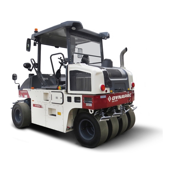
Introduction Introduction CP1200 Dynapac CP1200 is a 12 tones pneumatic tire roller with 5,77 ft. (1760 mm) width. It has 5 front wheels, and four back wheels. The flexible ballast solution and the wide range of option equipment indicate that the machine has different settings available. - Page 6 Introduction General Information This manual contains instructions to operate and perform the maintenance of the machine. The machine's maintenance shall be made correctly in order to obtain the maximum performance and the equipment shall also be kept clean, so leakage, loosen bolts and connections can be found as soon as possible.
-
Page 7: Safety - General Instructions
17. Do not make any changes on the machine, under the risk of affecting the personal safety as well the equipment's. Any change on the machine demands a previous written approval by DYNAPAC. 18. Avoid using the machine before the hydraulic oil reaches the normal operating temperature. - Page 8 Safety - General instructions 19. For your own protection, always wear: Helmet; Working boots with steel toecaps; Ear protectors; Reflecting clothing; Working gloves. 20. If there is a cab in the machine, operate it always with the doors closed and with the seat belt.
-
Page 9: Safety - When Operating
Safety Safety - When operating Avoid people entering at the danger area, that is, at a distance of at least 23 ft (7 m) in all the directions from the machine operating. The operator can allow one person to be at the danger area, but in this case, care must be taken and the machine can only be operated when this person is in a visible place or with clear... - Page 10 Safety Transport on steep ground During the transport on steep ground (slope >5%), be careful to not exceed the roller's maximum speed. Selecting the low speed will increase the engine brake system efficacy and also the life of the braking system. >5% (2,8°) Fig.: Steep ground v <...
-
Page 11: Safety - Option Items
Safety - Option items Safety – Option items Air conditioning The system contains pressurized refrigerant. It is forbidden to release refrigerant to the atmosphere. The maintenance of the air conditioning system shall be carried out only by trained people and with the proper tools and equipment. -
Page 12: Technical Specifications
Technical specifications Technical Specifications Vibrations – Operator station (ISO 2631) The vibration levels are measured according to the operational cycle described in the EU directive 2000/14/EC on machines equipped for the EU market with the operator’s seat in the transport position. The measured vibrations on the whole body are below the 0.5 m/s²... -
Page 13: Technical Specifications -Dimensions
Technical specifications Technical specifications -Dimensions Dimensions Dimensions inches A – Between axles 2760 108,6 B – Total width 2057 H1 – Total height 2576 101,4 H2 – Total height (Platform) 1875 73,8 K – Height from the ground 9,33 L – Total length 3650 143,7 2017-11-22... -
Page 14: Safety Decals - Description And Location
Safety decals - description and location Safety decals - description and location 4812325556EN 2017-11-22... - Page 15 Safety decals - description and location Safety decals - Description and location (cont.) Always make sure that all the safety decals are completely legible and remove the dirt or request for new ones if they are illegible. Use the part number indicated on each decal.
- Page 16 Safety decals - description and location Safety decals - Description and location (cont.) Emergency exit - Cab. Hoisting plate Tire pressure Diesel oil Securing point Lifting point Hydraulic oil 4812325556EN 2017-11-22...
- Page 17 Safety decals - description and location Safety decals - Description and location (cont.) Handbook compartment Master switch Battery voltage Sound power level Water tank Hydraulic oil level Do not spray with water 2017-11-22 4812325556EN...
-
Page 18: Identification Plates
Identification plates Identification plates Machine plate The machine plate (1) is on the front, on the left side of the operator's platform. It specifies the manufacturer's name, the type of the machine, the serial number, the service weight, the engine power and the manufacturing year (machines delivered outside EU do not present CE marking and in some cases they also do not present the manufacturing year). - Page 19 00123 123456 Number) A - Manufacturer's code (100 = Dynapac) B - Family/model code (00500 = CP1200 Tier 3) (00510 = CP1200 Tier 4) C - Check code D - Year of manufacturing (E=2014, F=2015...) E - Production's unit code (B = Sorocaba, Brazil)
-
Page 20: Instruments/Controls
Instruments/controls Instruments/controls Control panel, side panel and command keyboard Fig. Control panel, side panel and command keyboard. Ignition key Forward/reverse lever Command keyboard Direction lights (OPTION) Attention lights Warning lights High beam lights (OPTION) High/low speed Enable the regeneration (Tier 4 Engine) Disable the regeneration (Tier 4 Engine) Brake test Horn... - Page 21 Instrument/controls - Description and function Instrument/controls - Description and function DESIGNATION SYMBOL FUNCTION: The electric circuit is off. All instruments and electric controls are on. Ignition key The starter is activated. To turn on the machine, the lever must be in "Neutral ".
- Page 22 Instrument/controls - Description and function DESIGNATION SYMBOL FUNCTION: The sprinkling frequency increases each "+" increase of the sprinkler time the water volume on the wheels is also interval (timer) increased. The sprinkling frequency decreases each "-" decrease of the sprinkler time the water volume on the wheels is also interval (timer) decreased.
- Page 23 Instrument/controls - Description and function DENOMINAÇÃO SÍMBOLO FUNÇÃO Press it to turn off the machine and the Emergency stop button engine. All the power supply is also turned off. Hazard warning lights Press the switch to activate the hazard warning lights. Rotating beacon Press the switch to activate the rotating beacon.
- Page 24 Instrument/controls - Description and function Control panel – General description When the ignition key is in the position "I", the start screen is visible on the display. It remains activated for a few seconds then it switches to the status screen. Fig.
- Page 25 Instrument/controls - Description and function Control panel – General description (cont.) A menu field is shown by pressing one of the selection buttons. It is visible for a short time, then it fades out if no selection is made. A menu field appears again by pressing one of the selection buttons (1).
- Page 26 Instrument/controls - Description and function Control panel – Alarms When an engine motor alarm is activated, it is shown in the screen. The alarm is sent from the engine's ECM, which tracks its functions. The message displays SPN and FMI codes and can be read via the engine supplier error code list.
- Page 27 Warning symbol, low braking capacity. this alarm appears and remains with the machine working, stop it immediately and contact DYNAPAC. This symbol appears when there is a H1- Warning symbol, error: [XX] AC unit alarm. The error codes can be found in the H1-AC alarm table.
- Page 28 Instrument/controls - Description and function H1-AC Alarm ERROR DESIGNATION FUNCTION CODE SAFE MODE: <9V or >36V LIMITED MODE: <18V or SAFE/LIMITED Mode >32V Internal Reference Voltage SAFE Mode Analog Injection Channel SAFE Mode Watchdog (-) SAFE Mode Sensor Voltage Error SAFE Mode Pump Forward Control Valve Error/Feedback Error LIMITED Mode...
- Page 29 Instrument/controls - Description and function Control panel – Alarms (cont.) Alarms received are stored/logged and can be seen by selecting Display Alarms “ENGINE ALARM” Stored/logged engine alarms. “MACHINE ALARM” Stored/logged machine alarms. They come from other systems on the machine.. 2017-11-22 4812325556EN...
- Page 30 Instrument/controls - Description and function “USER SETTINGS” Users can change lighting settings, choose between Metric or Imperial system and set warning sounds on/off. Adjustment of light and contrast settings on the display, including brightness of the panel light. Operator help when starting 4812325556EN 2017-11-22...
- Page 31 Instrument/controls - Description and function When trying to turn on the machine without having set up to three necessary conditions to do so, the missing ones are shown in the display. The missing conditions must be set before turning on the machine. Conditions that must be set: - The parking brake shall be activated.
-
Page 32: Instruments And Controls - Cab
A/C – System operation Instruments and Controls - Cab DESIGNATION SYMBOL FUNCTION Press to operate the front windshield Front wiper switch wiper. Press to operate the rear windshield Rear wiper switch wiper. Press the top to activate the front Front and rear windshield washers washers. -
Page 33: A/C - System Operation
A/C – System operation A/C – System operation Power/Enter By feeding the panel with 12VDC, the screen will be on, indicating that the product is in standby mode. Press to turn on the A/C, it will show the software version and then the temperature. - Page 34 A/C – System operation Ventilation The controller has two ventilation modes: manual and automatic ventilation. Manual ventilation The manual ventilation has three speeds. When some function (cooling, heating or automatic mode) is active, the ventilation function is always on. To change the fan speed, press the key (Ventilation mode) and after set the desired speed with the keys After press the key...
- Page 35 Operation - Before starting Operation - Before starting Daily maintenance Before starting your work shift and operating the equipment, make sure the daily maintenance was carried out. For further information, refer to the maintenance section in this manual. Master switch Check if the master switch is on.
- Page 36 Operation - Before starting Standard operator's seat - adjustment Adjust the operator's seat so all the controls are within easy reach and the machine operation is comfortable. (1) Length adjustment. (2) Weight adjustment. (3) Back support adjustment. (4) Seat belt. ALWAYS make sure the seat is locked before starting the operation.
- Page 37 Operation - Before starting View Before starting the machine, make sure that the view forwards and backwards is unobstructed. All cab windows should be clean and the rear view mirrors should be correctly adjusted. Operator position If a ROPS (2) (Roll Over Protective Structure) or a cab is fitted to the roller, always wear the seat belt (1) provided and wear a protective helmet.
-
Page 38: Starting
Operation Starting Screen - Control Sit down for all operations. Turn the ignition key (1) to the position I and the initial screen is shown in the Control panel (2). Fig.– Side panel 1. Ignition key 2. Control Panel Check if the voltmeter (3) appoints at least 24 volt and if the fuel (4) and water (5) levels show a percentage value. - Page 39 Operation Starting the engine Make sure the emergency stop system (2) is off (upper position) and the parking brake is on. The forward/reverse lever (1) shall be in the neutral position. The Diesel engine cannot be started if the lever is not in this position.
- Page 40 Operation Display and button set The parking brake symbol is shown when the parking brake is activated. = Low speed. = Automatic water control (AWC). The sprinkling is activated when the forward/backward lever is in the neutral position. = Tire pressure. = High/low speed mode (in the center of the screen).
-
Page 41: Operating The Roller
Operation Operating the roller Under no circumstances the machine shall be operated away from the ground. The operator shall be seated inside the machine during the operation. Make sure the areas at the front and behind the machine are free. 1. - Page 42 Operation Tire pressure adjustment (option) The operator can vary the pressure during the operation with the tire air pressure control. It can be variable adjusted with the keys (2) and (3) on the keypad, within the interval from 240 kPa to 830 kPa (35 to 120 PSI) and can be reduced with the key (3).
-
Page 43: Ballast Box
Operation Ballast box Fig. – Ballast box cover Water and wet sand ballast Top forward covers Top covers Remove the top covers (1 e 2) and fill with water and sand Side covers Draining plugs through this opening. Keep the side covers (3) closed during the water filling. Do not remove the draining plugs (4) because the water may leak when the ballast is filled with it. - Page 44 Operation Removable steel ballasts The CP1200 roller uses an innovative and patented system of steel ballasts, which can be removed and installed easily and quickly: 1. With the ballast box drained (without water and/or sand), remove four side covers (1) from the ballast box.
- Page 45 Operation Ground pressure (driving) The tire contact surface can be changed by means of tire pressure. The high pressure on the tires provides a smaller contact surface (1) and the low pressure on the tire provides a larger contact surface (2). The contact surface with the ground is very important for the compaction result.
-
Page 46: Interlock/Emergency Stop/Parking Brake
Operation Interlock/Emergency Stop/Parking Brake The interlock, emergency stop and parking brake shall be checked daily before starting the machine. To check if the emergency stop and interlock are working correctly, it is necessary to turn on and off the machine. To check if the Interlock works correctly, the operator shall rise from the seat with the roller moving forwards and backwards (perform the... - Page 47 Operation Emergency braking For emergency braking, press the emergency stop button (1), hold the steering wheel and be ready for a sudden stop. The engine stops. The diesel engine is turned off and must be turned on again if necessary. When starting the engine after an emergency stop, the forward/backward lever shall be in the neutral position and the parking brake shall be on.
- Page 48 Operation Chocking the wheels Never leave the roller and let it with the engine running unless the parking brake is activated. Make sure the machine is parked in a safe area, without traffic. Chock the wheels when parking on slopes. In extremely cold weather, some components may freeze.
-
Page 49: Long-Term Storage
Long-term storage Long-term storage For long-term storage (more than a month) follow the instructions below: These measures are valid for storage for a period of up to 6 months. Before starting the machine again, the points stated below shall be performed before parking and store the roller. Wash the machine and touch up the painting finishing to prevent rusting. - Page 50 Long-term storage Hydraulic oil reservoir Fill the hydraulic reservoir until the uppermost level. Tires Make sure the tires pressure is at least 345kPa (50 PSI). Steering cylinder, hinges, etc. Grease the steering cylinder plunger spindle to preserve it. Also lubricate the hinges on the engine compartment and cab doors.
-
Page 51: Lifting
Lifting Lifting Lifting the roller Make sure the front wheels are parallel with the frame before lifting the roller. Make sure the hooks are safely placed in the lifting eyes. The equipment shall only be lifted by the proper lifting eyes. Always use cables and steel chains according to the safety norms and make sure there are no worn components and that parts are not damaged during... -
Page 52: Towing
Towing Towing Short distance towing with the engine running The roller can be moved up to 984 feet (300 meters), according to the following instructions: To tow the machine, use the same lifting points. 1. Park the roller on a flat and safe place. If necessary, chock the tires. - Page 53 Towing Short distance towing with engine inoperative As a safety measure, chock the wheels to prevent the machine to move when the brakes are hydraulically disengaged. The roller can be moved up to 984 feet (300 meters), according to the following instructions: Fig.
- Page 54 The pulling forces shall act to the machine's longitudinal axis, as illustrated in the figure. Refer to the table below to know the maximum pulling force allowed for this machine model: MODEL CP1200 40.465 Fig. - Towing direction Transport Preparing the roller for transport Apply the parking brake and make sure the machine is in the neutral position, that is, that the tires are pointing forwards.
-
Page 55: Operation Instructions - Overview
Operation instructions Operation instructions - Overview Follow the safety instructions specified in the Safety Manual. ● Make sure all the MAINTENANCE INSTRUCTIONS were carried out. For further information, refer to the Maintenance section in this manual. ● Turn on the battery switch. ●... -
Page 56: Preventive Maintenance
Preventive maintenance Preventive maintenance Introduction It is necessary to carry out a complete maintenance so the machine can work satisfactorily and at the lowest possible costs. The Maintenance section includes the periodic maintenance that shall be carried out on the machine. The recommended maintenance intervals assume that the machine is being used in a normal environment and working conditions. -
Page 57: Preventive Maintenance - Symbols And Lubricants
Antifreeze protection effective down to -34.6 GlycoShell/Carcoolant 774C F (-37ºC). 50/50 mixed (clean water + equivalent. coolant additive). For room temperatures extremely high or low, other lubricants shall be applied. Refer to the chapter "Special Instructions" or contact DYNAPAC. 2017-11-22 4812325556EN... - Page 58 Preventive maintenance - Symbols and lubricants Engine, oil level Engine, oil filter Hydraulic fluid, level Air filter Hydraulic fluid, filter Fuel filter Battery Coolant level 4812325556EN 2017-11-22...
- Page 59 Preventive maintenance - Symbols and lubricants Lubricating oil Air pressure Sprinkler Sprinkler water Recycling 2017-11-22 4812325556EN...
-
Page 60: Specifications
Specifications Specifications WEIGHTS Operational weight with ROPS and 5.106 kg series equipment (11.256 lb) Weight without ballast 4.706 kg (10.374 lb) Weight with ballast, wet sand 8.906 kg (19.634 lb) Weight with ballast 11.556 kg (25.476 lb) Weight with maximum ballast 12.000 kg (26.520 lb) FILLING VOLUMES... - Page 61 Specifications Torque Torque for oiled bolts tightened with a torque wrench. METRIC STRENGTH CLASS COARSE 8.8, oiled 10.9, oiled 10.9 12.9, oiled 12.9 SCREW THREAD, BRIGHT GALVANIZED (fzb) 8.4 N.m 9.4 N.m 12 N.m 13.4 N.m 14.6 N.m 16.3 N.m (9.9 lb.ft) (10.7 lb.ft) (12.02lb.ft)
- Page 62 Specifications Torque (cont.) METRIC COARSE STRENGTH CLASS THREAD, ZINC- 10.9 10.9 12.9 12.9 TREATED oiled oiled (Dacromet/GEOMET) 12 N.m 15 N.m 14.6 N.m 18.3 N.m (8.8 lb.ft) (11.06 lb.ft) (10.7 lb.ft) (13.4 lb.ft) 28 N.m 36 N.m 34 N.m 43 N.m (20.6 lb.ft) (26.5 lb.ft) (25.07 lb.ft)
- Page 63 Specifications Specifications (cont.) Air conditioning (option) The system described in this manual is the ACC (Automatic Climate Control), that is, a system which maintains the set temperature in the cab provided that all the windows and doors are kept closed. Coolant designation: HFC-R134:A Coolant weight when full: 1,350 g (2.98 lbs).
-
Page 64: Maintenance And Lubrication Points
Maintenance and lubrication points Maintenance and lubrication points Read carefully this manual section before carrying out any maintenance or lubrication on the machine. Always check the areas around and under the equipment. It is an easy way to detect earlier leakages and possible damages. -
Page 65: Scheduled Maintenance And Lubrication
Scheduled maintenance and lubrication Scheduled maintenance and lubrication The maintenance and lubrication shall be carried out first based on the working hours. When they cannot be considered, use the periods, like daily, weekly, etc. Always clean around the covers, plugs, grease nipples or hoods before open or apply grease to them. -
Page 66: Scheduled Maintenance
Scheduled maintenance Scheduled maintenance Pos. Action Pag. Note Check operation of the emergency brake Check the engine oil level Refer to the engine manual Check the level of engine coolant Check the hydraulic oil level Fill the w ater tanks ... - Page 67 Scheduled Maintenance Check operation of the emergency brake Make the machine move slowly. Hold the steering wheel and brace yourself for a sudden stop. Press the emergency brake button (1). The roller will stop abruptly and the engine will shut down.
- Page 68 3. If the oil level is 2 cm below the glass upper line, fill with the recommended hydraulic oil. Use only hydraulic oil recommended by DYNAPAC. Fig. - Hydraulic oil reservoir 1. Oil sight glass 2.
- Page 69 Scheduled Maintenance Nozzle - Disassembly / Cleaning Remove manually the clogged nozzle. Apply the nozzle (2) and fine filter (4) a compressed air jet. Alternatively, install replacement parts and clean the clogged later. After checking and cleaning possible, turn on the system and check its operation.
- Page 70 While refueling, hold the pump nozzle in contact with the oil fill tube. Always fill with fuel recommended by Dynapac. The use of adulterated fuel, contaminated, dirty or poor quality, damages the components of the injection and engine system.
- Page 71 Scheduled Maintenance Replace the hydraulic oil filters Hydraulic filters are located on the right side of the engine compartment. TAKE CARE OF THE ENVIRONMENT: All the used oil shall be properly stored for subsequent disposal. Do not dispose of oil on the ground, sewage system or other place which can harm the environment.
- Page 72 Scheduled maintenance Check the tightness of the wheel nuts Confirm the tightening torque of the wheel nuts (1) with 204 Nm (47kpm). Check all wheels and all nuts (this information is valid only for new machines or newly installed wheels). Fig.
- Page 73 (2) with five applications of the manual pump. Use the grease in accordance with the recommended lubricant specifications for Dynapac. Fig. – Articulated bearings 1. Upper pivot bearing grease 2. Lower pivot bearing grease Check and clean the radiators Make sure that the air flow is passing freely through the radiators without obstruction.
- Page 74 Scheduled maintenance Loosen the hex nut, pull the hose out and release the oil drain plug. 1. Let all the oil drain into the container and finish the operation , attach the drain plug back and attach the hose. Then tighten the hex nut.
- Page 75 Scheduled Maintenance Check the hydraulic oil tank cover To check the hydraulic oil tank cap: Unscrew the tank cap and check if it’s obstructed. The air must flow freely throughout the cap in both ways. 2. If one way is obstructed, wash the filter with a small portion of Diesel oil and use compressed air until the obstruction is eliminated or replace the cap for a new one.
- Page 76 Scheduled maintenance Replace the cab air filter Use a step ladder to reach the filter (1). The filter can also be accessed by the window at the right side of the cab. The filter is located at the front of the cab. Remove three bolts and the protective plastic.
- Page 77 Scheduled Maintenance TAKE CARE OF THE ENVIRONMENT: All used coolant shall be properly collected and store for subsequent recycling. Do not dispose of the coolant on the ground, sewage system or other place which can harm the environment. 4. Unscrew the hexagon nut, remove the hose and unscrew the drain plug.
- Page 78 Scheduled maintenance Empty and clean the water tank Wash the water tank adding a small quantity of a suitable detergent for plastic surfaces. Remove the water filter to empty the tank. water tank made plastic (polyethylene) and can be recycled. Fig.
-
Page 79: Electrical System
Scheduled Maintenance Electrical system The machine's main control box (1) is located on the rear of the operator platform. There is a plastic cap over it and the fuses. A 12V jack is available in the plastic cap. Fig. - Main control box 1. - Page 80 Scheduled maintenance Cab fuse box 1. Indoors lighting (10A) 2. Windscreen wiper/washers, front/rear (10A) 3. Heating (15A) 4. Empty 5. Empty 6. Empty 7. Empty Fig. - Cab fuse box 8. Empty Main fuse box 9. Main fuse (50A) 10. Empty 11.
- Page 82 Dynapac do Brasil Industria e Comercio de Maquinas Ltda. Rua Georg Schaeffler, 430, Sorocaba/SP, Brasil Tel.: +55 (15) 3412-7500 Fax.: +55 (15) 3412-7522 www.dynapac.com...
Need help?
Do you have a question about the CP1200 and is the answer not in the manual?
Questions and answers