
Related Manuals for WAGO 750-404


Summary of Contents for WAGO 750-404
- Page 1 Fieldbus Independent I/O Modules Counter Modules 750-404, (/xxx-xxx) Manual Version 1.2.0...
- Page 2 • General Copyright 2012 by WAGO Kontakttechnik GmbH & Co. KG All rights reserved. WAGO Kontakttechnik GmbH & Co. KG Hansastraße 27 D-32423 Minden Phone: +49 (0) 571/8 87 – 0 Fax: +49 (0) 571/8 87 – 1 69 E-Mail: info@wago.com...
-
Page 3: Table Of Contents
2.1.2.8 Examples..................21 2.1.2.8.1 750-404 ..................21 2.1.2.8.2 750-404/000-002 ..............23 2.1.2.8.3 750-404/000-004 ..............24 2.1.3 750-404/000-001 [Up Counter / Enable Input] ......... 25 2.1.3.1 View....................25 2.1.3.2 Description..................25 2.1.3.3 Display Elements ................26 2.1.3.4 Schematic Diagram............... 27 2.1.3.5 Technical Data ................ - Page 4 • Content 2.1.4.8 Example ..................40 2.1.5 750-404/000-005 [2 Up Counter/16 Bit/5 kHz] ........ 42 2.1.5.1 View ....................42 2.1.5.2 Description..................42 2.1.5.3 Display Elements ................44 2.1.5.4 Schematic Diagram ............... 44 2.1.5.5 Technical Data ................45 2.1.5.6 Process Image ................46 2.1.5.7...
-
Page 5: Important Notes
Co. KG, Minden, Germany. Non-observance will involve the right to assert damage claims. WAGO Kontakttechnik GmbH & Co. KG reserves the right to provide for any alterations or modifications that serve to increase the efficiency of technical progress. WAGO Kontakttechnik GmbH & Co. KG owns all rights arising from the granting of patents or from the legal protection of utility patents. -
Page 6: Use Of The 750 Series In Compliance With Underlying Provisions
Legal Bases All responsible persons have to familiarize themselves with the underlying legal standards to be applied. WAGO Kontakttechnik GmbH & Co. KG does not assume any liability whatsoever resulting from improper handling and damage incurred to both WAGO´s own and third-party products by disregarding detailed information in this Manual. -
Page 7: Standards And Guidelines For Operating The 750 Series
(emissions of interference) in compliance with EN 61000-6-3. You will find the detailed information in section "WAGO-I/O-SYSTEM 750" "System Description" "Technical Data". Please observe the safety precautions against electrostatic discharge in accordance with DIN EN 61340-5-1/-3. -
Page 8: Symbols
Observe the precautionary measure for handling components at risk of electrostatic discharge. Note Make important notes that are to be complied with so that a trouble-free and efficient device operation can be guaranteed. Additional Information References to additional literature, manuals, data sheets and internet pages. WAGO-I/O-SYSTEM 750 I/O Modules... -
Page 9: Safety Information
Danger The WAGO-I/O-SYSTEM 750 and its components are an open system. It must only be assembled in housings, cabinets or in electrical operation rooms. Access is only permitted via a key or tool to authorized qualified personnel. -
Page 10: Font Conventions
Only for use in LAN, not for connection to telecommunication circuits. 1.4 Font Conventions Names of paths and data files are marked in italic-type. italic e.g.: C:\Programs\WAGO-IO-CHECK Menu items are marked in italic-type, bold letters. italic e.g.: Save A backslash between two names characterizes the selection of a menu point from a menu. -
Page 11: Scope
• 11 Scope 1.6 Scope This manual describes the Special Module 750-404, (/xxx-xxx) Counter Modules of the modular WAGO-I/O-SYSTEM 750. Handling, assembly and start-up are described in the manual of the Fieldbus Coupler/Controller. Therefore this documentation is valid only in the connection with the appropriate manual. -
Page 12: O Modules
12 • Overview Counter Modules 750-404, (/xxx-xxx) 2 I/O Modules 2.1 Specialty Modules 2.1.1 Overview Counter Modules 750-404, (/xxx-xxx) 750-404/ 750-404/ 750-404/ 750-404/ 750-404/ I/O Module 750-404 000-001 000-002 000-003 000-004 000-005 Function Up / Peak Time Frequency Up / Down... -
Page 13: 750-404 [Up/Down Counter /100 Khz]
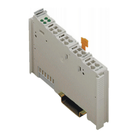
Fig. 2.1.2-1: View g040400e 2.1.2.3 Description The Up/Down counter 750-404 and the variation 750-404/000-004 is capable of counting binary pulses of DC 24 V at the input CLOCK and then transmits the data to the fieldbus. The counter module 750-404/000-002 begins processing with pulses at the CLOCK input and counts the pulses in a special time span. - Page 14 Description The counter can be set or reset with the control byte. The digital outputs DO 1 and DO 2 of the counter module 750-404 and the variation 750-404/000-002 are activated through bits in the control byte. The digital outputs DO 1 and DO 2 of the counter module 750-404/000-004 are activated depending on the counter reading or through bits in the control byte.
-
Page 15: Display Elements
750-404 [Up/Down Counter /100 kHz] • 15 Display Elements 2.1.2.4 Display Elements Channel Meaning State Input U/D: Signal voltage (0), Backwards counting Status Input U/D: Signal voltage (1), green Forward counting 13 14 Digital Output DO 1 reset Status DO 1... -
Page 16: Technical Data
16 • 750-404 [Up/Down Counter /100 kHz] Technical Data 2.1.2.6 Technical Data Module Specific Data Number of outputs Number of counters Output current 0.5 A short-circuit-protected Current consumption (internal) 15 mA Voltage via power jumper contacts DC 24 V (-15 % ... + 20 %) Signal voltage (0): DC –3 V ... -
Page 17: Process Image
WAGO-I/O-SYSTEM 750 System Description 2.1.2.7 Process Image Using the I/O module 750-404, a 5 byte input and output process image can be transferred to the fieldbus coupler / controller via one logical channel. The transfer of the setting counter value in binary format is made via 4 output bytes (D0 ... -
Page 18: Control- / Status Byte 750-404
750-404 [Up/Down Counter /100 kHz] Process Image 2.1.2.7.1 Control- / Status byte 750-404 The control byte C0 serves for setting and locking the counter and for setting the outputs. The status byte S0 shows the status of the counter and the inputs and outputs. -
Page 19: Control- / Status Byte 750-404/000-002
750-404 [Up/Down Counter /100 kHz] • 19 Process Image 2.1.2.7.2 Control- / Status byte 750-404/000-002 The control byte C0 serves for starting the periodic counter pulse measurement and for setting the outputs. The status byte S0 shows the status of the counter and the inputs and outputs. -
Page 20: Control- / Status Byte 750-404/000-004
20 • 750-404 [Up/Down Counter /100 kHz] Process Image 2.1.2.7.3 Control- / Status byte 750-404/000-004 The control byte C0 serves for setting and locking the counter and for setting the outputs dependent or independently on the counter reading. The status byte S0 shows the status of the counter and the inputs and outputs. -
Page 21: Examples
750-404 [Up/Down Counter /100 kHz] • 21 Examples Set Outputs: Bits 2 and 3 set the digital outputs DO 1 and DO 2 of the counter module. If bits 2 or 3 are also set, they have priority before bits 0 and 1, so that the corresponding output is set independent of the counter reading. - Page 22 22 • 750-404 [Up/Down Counter /100 kHz] Examples Up counting: Attention For counting up, 24 V must be applied to input U/D. 6. Wait for the first and further count pulses. During counting, the data bytes D0 to D3 of the input data appear as...
- Page 23 750-404 [Up/Down Counter /100 kHz] • 23 Examples 2.1.2.8.2 750-404/000-002 1. The counter counts up (the input U/D is set at 24 V). The counter reading is 0. The timer interrupts. No count pulse received on the input CLOCK. Control byte...
- Page 24 24 • 750-404 [Up/Down Counter /100 kHz] Examples 6. The cyclic period measurement is running. Stopping the cyclic recording was requested. The process data supply the counter reading, which was registered in the previous cycle. Control byte Input bit Value...
-
Page 25: 750-404/000-001 [Up Counter / Enable Input]
750-404/000-001 [Up Counter / Enable Input] • 25 View 2.1.3 750-404/000-001 [Up Counter / Enable Input] Up Counter / Enable Input, DC 24 V, 100 kHz 2.1.3.1 View 13 14 Status Status GATE CLOCK DO 1 DO 2 Data contacts... -
Page 26: Display Elements
Use an appropriate supply module (e.g. 750-602) if an electrically isolated voltage supply is required! The module 750-404/000-001 can be used with all couplers/controllers of the WAGO-I/O-SYSTEM 750 (except for the economy types 750-320, 750-323, 750-324 and 750-327 and the ModBus controllers 750-812, 750-812/025-000 and 750-814). -
Page 27: Schematic Diagram
750-404/000-001 [Up Counter / Enable Input] • 27 Schematic Diagram 2.1.3.4 Schematic Diagram GATE GATE CLOCK 270pF CLOCK 270pF 10nF 10nF GATE Logic 10nF CLOCK 270pF DO 2 DO 1 750-404 /000-001 Fig. 2.1.3-3: Schematic Diagram g040411e WAGO-I/O-SYSTEM 750 I/O Modules... -
Page 28: Technical Data
Conformity Marking More Information Detailed references to the approvals are listed in the document "Overview Approvals WAGO-I/O-SYSTEM 750", which You can find on the CD ROM ELECTRONICC Tools and Docs (Item-No.: 0888-0412-0001-0101) or in the Service Downloads ... -
Page 29: Process Image
• 29 Process Image 2.1.3.6 Process Image Using the I/O module 750-404/000-001, a 5 byte input and output process image can be transferred to the fieldbus coupler / controller via two logical channels. The transfer of the setting counter value in binary format is made via 4 output bytes (D0 ... -
Page 30: Example
30 • 750-404/000-001 [Up Counter / Enable Input] Example With the control and status byte the following tasks are possible: Set Counter: Put Bit 5 into the control byte. The counter with the 32 bit value is loaded into output bytes 0-3. As long as the bits are set, the counter can stop and information is stored. - Page 31 750-404/000-001 [Up Counter / Enable Input] • 31 Example Up counting: Attention For counting up, 24 V must be applied to input GATE. 13.Wait for the first and further count pulses. During counting, the data bytes D0 to D3 of the input data appear as...
-
Page 32: 750-404/000-003 [Frequency Counter 0.1 Hz-100 Khz]
The counter module also can be ordered as frequency counter module with 750-404/000-003. The counter module 750-404/000-003 measures the period of the 24 V DC input signal at the input CLOCK and converts it into a corresponding frequency value. The measurement is enabled if the input GATE is an open circuit input or 0V. - Page 33 Use an appropriate supply module (e.g. 750-602) if an electrically isolated voltage supply is required! The module 750-404/000-003 can be used with all couplers/controllers of the WAGO-I/O-SYSTEM 750 (except for the economy types 750-320, 750-323, 750-324 and 750-327 and the ModBus controllers 750-812, 750-812/025-000 and 750-814).
-
Page 34: Display Elements
34 • 750-404/000-003 [Frequency Counter 0.1 Hz-100 kHz] Display Elements 2.1.4.3 Display Elements Channel Meaning State Input GATE: Signal voltage (0), Measurement released Status GATE Input GATE: Signal voltage (1), green Measurement disabled 13 14 Digital Output DO 1 reset... -
Page 35: Technical Data
750-404/000-003 [Frequency Counter 0.1 Hz-100 kHz] • 35 Technical Data 2.1.4.5 Technical Data Module Specific Data Number of outputs Number of counters 0.5 A short-circuit-protected Output current Current consumption 75 mA at DC 5 V max. Voltage via power jumper contacts DC 24 V (-15 % ... -
Page 36: Functional Description
Conformity Marking More Information Detailed references to the approvals are listed in the document "Overview Approvals WAGO-I/O-SYSTEM 750", which You can find on the CD ROM ELECTRONICC Tools and Docs (Item-No.: 0888-0412-0001-0101) or in the Service Downloads ... -
Page 37: Process Image
(integration time = 1 period) 2.1.4.7 Process Image Using the I/O module 750-404/000-003, a 5 byte input and output process image can be transferred to the fieldbus coupler / controller via two logical channels. The two output bytes (D0, D1) contain the setting Watchdog time in binary format. - Page 38 38 • 750-404/000-003 [Frequency Counter 0.1 Hz-100 kHz] Process Image Input data Output data Status byte Control byte Frequency value byte 0 (LSB) Watchdog-time byte 0 (LSB) Frequency value byte 1 Watchdog-time byte 1 (MSB) Frequency value byte 2 reserved...
- Page 39 750-404/000-003 [Frequency Counter 0.1 Hz-100 kHz] • 39 Process Image Measuring RANGE_ RANGE_ Maximum Measured – method SEL1 SEL0 frequency range value display Integration over ... 0.1 Hz ... 8 kHz 1 period Frequency in 1/1000 Hz 0.25 Hz ... 32 kHz...
-
Page 40: Example
40 • 750-404/000-003 [Frequency Counter 0.1 Hz-100 kHz] Example Attention The range of the watchdog timer stretches from 0 to 16383ms (0x0000 to 0x3FFF) in steps of 1ms per digit. Values which raise the permitted range of the watchdog timer are masked with 0x3FFF. - Page 41 750-404/000-003 [Frequency Counter 0.1 Hz-100 kHz] • 41 Example Change the Watchdog Time: The Watchdog time is change to 5000 ms (hexadecimal value 0x1388). 17.Write the new Watchdog time value into the output bytes. The data bytes D0 to D3 of the output data then read as follows:...
-
Page 42: 750-404/000-005 [2 Up Counter/16 Bit/5 Khz]
42 • 750-404/000-005 [2 Up Counter/16 Bit/5 kHz] View 2.1.5 750-404/000-005 [2 Up Counter/16 Bit/5 kHz] 2 Up Counter 16 Bit, DC 24 V, 5 kHz 2.1.5.1 View 13 14 Status Status CLOCK 2 CLOCK 1 DO 1 DO 2... - Page 43 Use an appropriate supply module (e.g. 750-602) if an electrically isolated voltage supply is required! The module 750-404/000-005 can be used with all couplers/controllers of the WAGO-I/O-SYSTEM 750 (except for the economy types 750-320, 750-323, 750-324 and 750-327 and the ModBus controllers 750-812, 750-812/025-000 and 750-814).
-
Page 44: Display Elements
44 • 750-404/000-005 [2 Up Counter/16 Bit/5 kHz] Display Elements 2.1.5.3 Display Elements Channel Meaning State Input CLOCK 2: Signal voltage (0) Status Input CLOCK 2: Signal voltage (1), CLOCK 2 green Counting pulse 2 13 14 Digital Output DO 1 reset... -
Page 45: Technical Data
Conformity Marking More Information Detailed references to the approvals are listed in the document "Overview Approvals WAGO-I/O-SYSTEM 750", which You can find on the CD ROM ELECTRONICC Tools and Docs (Item-No.: 0888-0412-0001-0101) or in the Service Downloads ... -
Page 46: Process Image
750-404/000-005 [2 Up Counter/16 Bit/5 kHz] Process Image 2.1.5.6 Process Image Using the I/O module 750-404/000-005, a 5 byte input and output process image can be transferred to the fieldbus coupler / controller via two logical channels. The transfer of the setting counter values in binary format is made via 4 output bytes (D0, D1) or (D2, D3) and the transfer of the counter reading in binary format is made via 4 input bytes (D0, D1) or (D2, D3). -
Page 47: Example
750-404/000-005 [2 Up Counter/16 Bit/5 kHz] • 47 Example With the control and status byte the following tasks are possible: Set Counter: Put Bit 5 (4) into the control byte. The counter 1 (2) with the 16 bit value is loaded into output bytes 0 (1) or 2 (3). - Page 48 48 • 750-404/000-005 [2 Up Counter/16 Bit/5 kHz] Example 27.Wait for the first and further count pulses. During counting, the data bytes D0 to D3 of the input data appear as follows: Data bytes Remark no count pulse 0x00 0x00...
- Page 49 750-404/000-005 [2 Up Counter/16 Bit/5 kHz] • 49 Example WAGO-I/O-SYSTEM 750 I/O Modules...
- Page 50 WAGO Kontakttechnik GmbH & Co. KG Postfach 2880 • G-32385 Minden Hansastraße 27 • G-32423 Minden Phone: 05 71/8 87 – 0 Fax: 05 71/8 87 – 1 69 E-Mail: info@wago.com Internet: http://www.wago.com...
Need help?
Do you have a question about the 750-404 and is the answer not in the manual?
Questions and answers