Advertisement
Quick Links
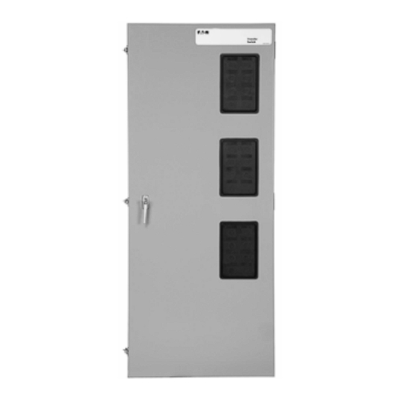
O & M Manual for 30-1000 Amperes
Manual Transfer Switch
Instruction Booklet
Description
Introduction . . . . . . . . . . . . . . . . . . . . . . . . . . . . . . . 2
Receiving, Handling, and Storage . . . . . . . . . . . . . . . . . 5
Equipment Description. . . . . . . . . . . . . . . . . . . . . . . . . 6
Installation and Wiring . . . . . . . . . . . . . . . . . . . . . . . . 10
Operation . . . . . . . . . . . . . . . . . . . . . . . . . . . . . . . . . 17
Testing and Problem Solving . . . . . . . . . . . . . . . . . . . . 18
Maintenance . . . . . . . . . . . . . . . . . . . . . . . . . . . . . . . 19
IB140058EN
Page
For more information visit: www.eaton.com
Advertisement

Related Manuals for Eaton MTVXKDA20225WRU


Summary of Contents for Eaton MTVXKDA20225WRU
-
Page 1: Table Of Contents
Testing and Problem Solving ....18 Maintenance ....... 19 IB140058EN For more information visit: www.eaton.com... -
Page 2: Introduction
SHOWN IN FIGURE 1. the information, recommendations and descriptions contained herein. In no event will Eaton be responsible to the purchaser or user in contract, in tort (including negligence), strict liability or otherwise for any special, indirect, incidental or consequential... - Page 3 The catalog number MTVXKDA30300XSU describes a Manual transfer switch with the switching devices mounted vertically in the enclosure. The Eaton Series CT Type HKD is used as the switching device and is in the form of a 3-pole molded case switch on each source.
- Page 4 Figure 3. Vertical Design Automatic Transfer Switch Equipment Figure 4. Vertical Design Automatic Transfer Switch Equipment with Deadfront Cover in Place Over Power Panel (225 - 1000 Shown with Deadfront Cover Removed (225 - 1000 Amperes). Amperes) For more information visit: www.eaton.com IB140058EN...
-
Page 5: Receiving, Handling, And Storage
Record any external and internal damage for reporting to the transportation carrier and Eaton, once a thorough inspection is complete. All claims should be as specific as possible and include the Shop Order and General Order numbers. -
Page 6: Equipment Description
The equipment warranty will not be applica- ble if there is evidence of outdoor storage. If the equipment Eaton transfer switch equipment is available in four different is to be stored indoors for any period of time, it should be configurations: stored with its protective packaging material in place. - Page 7 (Figure 14). Figure 8. Molded Case Switches Mounted in Vertical Design (Transfer Mechanism Removed for Clarity) IB140058EN For more information visit: www.eaton.com...
- Page 8 Cable entry holes are the 2. DP-4000 - Normal or Emergency, or Both N&E (Selectable) or responsibility of the customer. Load line 3. Custom metering available contact Eaton. For more information visit: www.eaton.com IB140058EN...
- Page 9 Eaton transfer switch equipment enclosed in a NEMA 1 enclosure is UL listed for application. In addition, Eaton Transfer Switches The standard switch enclosure is NEMA Type 1 for general indoor are listed by Underwriters Laboratories Inc.
-
Page 10: Installation And Wiring
Enclosure designs are, however, available for special environ- ments. If there are any doubts as to location suitabil- ity, discuss it with your Eaton representative. Check to make certain that there are no pipes, wires or other mounting hazards in the immediate mounting area that could cre- ate a present or future problem. - Page 11 Step 3: Gently lift the enclosure and guide the elongated holes in the upper mounting flange over the upper mounting bolts, but do not completely tighten the bolts. IB140058EN For more information visit: www.eaton.com...
- Page 12 Note: There are grooves in the back of the power panel and in the mount- ing bracket that keep the polyester phase barriers in their proper positions. Figure 13. Vertical Design Load Lug Assembly Shown Mounted For more information visit: www.eaton.com IB140058EN...
- Page 13 When making any bolted connection to the bus, comply Type LD 25 (33.8) with the torque requirements as outlined in Table 4. Type MD 25 (33.8) Type NB 25 (33.8) IB140058EN For more information visit: www.eaton.com...
- Page 14 This will line up the four correct Step 12: Reconnect the connector plugs and the transfer switch mounting holes in the power panel with the pre-tapped equipment is now configured for bottom entry. inserts in the rear of the enclosure. For more information visit: www.eaton.com IB140058EN...
- Page 15 Also verify that the cables comply with local electrical codes. Standard transfer switch equipment, as supplied from the factory, will accommodate the wire sizes shown in Table 5. IB140058EN For more information visit: www.eaton.com...
- Page 16 Horizontal design transfer switches are furnished with an adjust- able line voltage plug and receptacles below the power panel. To change the line voltage, remove the covers and insert the plug in the desired receptacle (Figure 17). For more information visit: www.eaton.com IB140058EN...
-
Page 17: Operation
ATS into the desired position. Let go of the brake release lever to re-engage the motor. Figure 19. Indicator Wheel Indicating Neutral Position on Vertical Figure 17. Transfer Switch Manual Operating Handle in Use on Design. Vertical Design. IB140058EN For more information visit: www.eaton.com... -
Page 18: Testing And Problem Solving
If a problem persists after having completed the problem solving operates properly. This attention to detail will help avoid unex- procedure, contact a Eaton representative for further assistance. pected malfunctions. Mechanical and/or electrical tests should be When calling for assistance, the following is the minimum informa- performed. -
Page 19: Maintenance
If a switching device is used for frequent switching during normal operation, this step can permit wiping action by the contacts. be disregarded. g. Return transfer switch equipment to service. Make certain all barriers are in place and doors closed. Re-apply secondary and primary power. IB140058EN For more information visit: www.eaton.com... - Page 20 DEALING OR USAGE OF TRADE, ARE MADE REGARDING THE INFORMATION, RECOMMENDATIONS AND DESCRIPTIONS CON- TAINED HEREIN. In no event will Eaton be responsible to the pur- chaser or user in contract, in tort (including negligence), strict liability or otherwise for any special, indirect, incidental or conse-...
Need help?
Do you have a question about the MTVXKDA20225WRU and is the answer not in the manual?
Questions and answers