Advertisement
Quick Links
Advertisement

Related Manuals for Samwha DSP DSP-VIP-PL


Summary of Contents for Samwha DSP DSP-VIP-PL
- Page 1 Voltage-Current based Digital Multi-function Motor Protection Relay DSP-VIP-PL/PM...
- Page 3 Content 1. System Construction 2. Detailed Structure 3. Main Feature 4.Specialized Point 5.Function List 6.Technical Specification 7.Protection List 8.Indication List 9.Auxiliary Function 10.Self-diagnostics table 11.Input-Output Terminal 12.Relay Output 13.Presetting Description 14.Control Key Operation 15.Time based Trip Relay Output 16.Trip Indication 17.Current Range Table for external CT 18.Time-Current Characteristics 19.Application Sequence Diagram...
- Page 4 DSP-VIP-PL/PM Voltage-Current based Digital Multi-function Motor Protection Relay 1.System Construction ○ DSP-VIP-PL/Panel Mounting Type Loader RS232 RS232 Converter Comm.Module ○ DSP-VIP-PM/ Panel Flush Mounting Type Display Meter Cable/RS232 RS232 Converter Comm.Module...
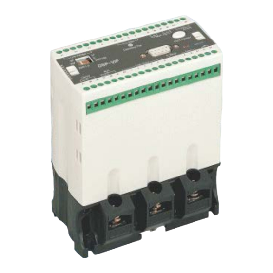
- Page 5 2.Detailed Structure ○ Converter 3 Colour LED/Power(G),Operating(R),Trip(Y) 9 PIN D-SUB/RS-232< > Loader Lock Holder Test/Reset Functional DIP SW IN-OUT Termial 9 PIN D-SUB/ RS-232< >Comm. Module CT Block Air Vent Wire Terminal DIN Rail Moving Tip Wire Turn Hole Screw Hole ○...
-
Page 6: Communication Module
○ Display Meter 9 PIN D-Sub/ RS232< > Converter 5 Digit Display by Cable Connector Phase LED Menu Bar Round Bar Grapgh Lock Cover Back View Control Key:w/Back Key Cover Light Mode Front View ○ Communication Module Status RJ45 Connector Hole DIP SW/4P:Termination With Cover/Input Resistence,485-422... - Page 7 ”rota” mode/ Possible to fix one of circulated factor or to release:one touch for CLR Key • To show load factor(actual/setting)/65% ~ 100%:Line Type/DSP-VIP-PL ,Round Type/DSP-VIP-PM • To check preset value during motor run:done by adjusting "SET" & "Mode" key *Press "SET"...
- Page 8 To act as actual complexed meter:V,I,KW,PF,KWH,Temp *Voltage Select:110V/220V/380V/440V/480V(110V is secondary voltage of PT) *Current Meter with CT:0.5A~3600A(Auto Range for decimal point) *KW Meter:0.1~60000KW(Auto Range) *Power Factor Meter: ± 0%~100% *KWH Meter:1KWH~99999999KWH(used "K" unit LED) *Temperature Meter:0 C ~ 150 *Auto Range: to indicate decimal point in conjunction with "K/Test"...
- Page 9 Remote Control through RS-485/422 digital communication Various communication module function * CM44 : 485/422,Modbus/RTU * MWR-S : 485,Modbus/RTU, 1 month data record/recording interval:50msec/max Basically 4~20mA output : 20mA for maximum current value among 3 phase To realize effective system for digital comminication:possible to combine a module simply if necessary ...
- Page 10 Acceptable with both rating of ZCT High Level Protetion Class...
- Page 11 Convenient Communication Module : DSP-CM-44, MWR-S a. the interface between Note PC and DSP directly by RS232 Note:If DSP is connected through a 9 pin port in PC, the wiring must be changed as follows: b.Communication module(CM-44)
- Page 12 ※Note:The detail about MWR-S(485 & recorder) is described in the manual for MWR-S Various and Multiple Indication...
-
Page 13: Function List
Duplex to sense Alarm/ slight Higher/ mech. Lower Shock 5.Function List DSP-VIP-PL DSP-VIP-PM Function Converter Comm. Converter+ Comm. + Loader Module D. Meter Module Over Load/ Protection Over Current Under Load/ Under Current Over Voltage Under Voltage Phase Loss by... -
Page 14: Technical Specification
Short/Available for Type 10 Ground Fault Over temperature Indication Line Voltage ur ent 3 Phase power Power factor Accumulated working time Load factor /Bar graph Auxiliary Y-D Timer 2 Level Alarm Forward-Reverse ON-OFF Ma n c ntac or Auto Close Communication 4~20mA RS 485,Modbus RS 232... - Page 15 over/under voltage 0.1~30 sec/def trip delay time (ouPt ) over load/current 0.1~60 sec/def,5~30class/inv:refer curve trip delay time(ot ) under 0.1~30 sec/def load/current trip delay time(ut ) Shock/stall trip 0.05 sec/instant, 0.1 ~ 3 sec/def delay time(st) Ground fault OFF,1 ~ 25 sec/def starting delay time(Edt) Ground fault trip...
- Page 16 *110VAC:75∼150VAC,50/60Hz(110∼220 VDC)/Optional Max Conductor Size 25sq Screw Torque Max 0.6 N.m Insulation Resistence/IEC-60255-5 10Mohm or more/500VDC,circuit-case High Voltage Withstand Test/ *circuit-case:AC 2000V,60Hz, 1 min IEC-60255-5 *contact-contact:AC 1500V,60Hz,1 min Lightning Impulse Voltage Withstand *Circuit-Ground,Circuit-Circuit:1.2/50uS,5KV Test)/ IEC-60255-5 *Control Circuits:1.2/50uS, 3KV 1 MHz Burst Immunity Test: IEC- 60255 2.5KV,Positive/Negative under -22-1 2sec...
- Page 17 Under Voltage *110V:70~110 *The 3 phase voltage under lower level of *220V:150~220 each range is not sensed,but assumed *380V:310~380 zero. *440V:370~440 *The trip caused by a voltage is reset *480V:410~480 automatically after recovering to level of preset value *If line voltage is under preset value in initial starting state,motor can not start.
-
Page 18: Indication List
Ground Fault Trip is done if a current *according to selection of DIP SW:ZCT greater than preset zero rating is used for 200mA/1.5mA or phase current is kept for 200mA/100mV Eot(earth operating time) Over *Trip is done if the temperature temperature sensed by PT100 greater than preset temperature is kept over 8... -
Page 19: Auxiliary Function
KWH Load factor by *calculating % as followed. bar graph [actual load curr./preset curr.]*100[%] or [actual load kw/preset load kw]*100[%] *Line type/DSP-VIP-PL ,round type/DSP- VIP-PM *indicating only ALhc(higher level alarm) Alarm before *preset "AL" in "Au-o" mode ,then make trip level % in "Alhc"... - Page 20 Self-diagnostics *Main trip relay will be trip(energized) after count down a preset o-time(dt or time of 550% in inverse) in "Test" SW of converter or in press "CLR" SW for 3 sec to check if a self-function is normal or not.
-
Page 21: Input-Output Terminal
11.Input-Output Terminal ▶ External ZCT type/possible matched with external CT ▶ Embeded ZCT type/not possible matched with external CT Division Description Feature Terminal 3P-1P 3P/1P 3 phase/Single phase KW-C Load-current Z1,Z2 External ZCT 200/1.5mA-200/100mV 85~260VAC,50/60Hz/ A1+,A2- Control Power 90~370VDC V1,V2,V3 Input Line Voltage Motor Earth... - Page 22 REVERSE START Remote Control Sensor/must be matched logic #1 to start and stop a motor Meter run(MCC) External Fault Input Temperature A,B,B+ PT100 Operating Power ON : 3 Tone Colour LED Green State stop state Yellow Trip MAIN TRIP 97-98 Changeable to ALLc VOLTAGE TRIP 27-28...
- Page 23 → Panel Mounting Type : Loader 12.Trip Relay Output Trip Relay Output Remark *Over Load/OverCurrent Output for short protecction comes out *Under Load/Under Current through main trip or Aux *Locked Rotor trip *Phase Loss *Reverse Phase C1-SC/F- Main MC/R :1a X 3 *Ground Fault *Over Temperature *Current Unbalance...
- Page 24 *In case "voltage" is selected in Line Mode .Over Voltage Trip .Under Voltage Trip .Voltage Unbalance *In case "OFF" is selected in Line Mode -Lower alarm level(ALLc) to OC,30%~ under Alhc level -Contact is closed after 3 sec under preset alarm 1a,Normal level,but main trip relay is OV/UV...
- Page 25 LInE/oFF/ to select a value *to select voltage range of incoming line 440V 110/220/38 of line voltage *OFF:to make disable a protection at a one time 0/440/ for phase loss ,reverse phase based on line voltage,over(oP) and under(uP) voltage *this disable execution takes a priority from ON/OFF of each mode(oP,uP) about voltage ,also consequently,output of OV/UV is changed into the output of lower level alarm(ALLc)
- Page 26 ▸Available range:100~(210/”oc” value)*100[%] Ot/oFF/set to preset to preset time to make a trip when Load(KW) or C ting value operating trip exceeds preset value 5 sec delay time *definite:0.1sec ~ 60sec *inverse:5 ~ 30 Class Lc/oFF / to protect *OFF:disable for this mode Locked Rotor -Otc=Def/Inv:dt+0.1sec if starting current exceeds 300% to oc during dt, Lc is shown in...
- Page 27 oP/OFF/ to protect over *to preset a value to protect over voltage setting voltage concerned with LInE mode value *110V:110~150,220V:220 ~ 290V,380 : 380~450V,440: 440~510V, 480V:480~550V *a trip by over voltage is reset automatically in case actual voltage is reached over preset value *OFF:the output of OV/UV is changed into the "SS"...
- Page 28 Test *This is done by test sw on the converter or by pressing "CLR" key for 3 sec or more *to check if this relay is ready to work normally or not. *main trip output will be trip after counting down preset o-time (definite T-I;o-time, inverse T-I:550% time of its class) *need to make a reset to enter into operational condition as pressing “Reset SW in Converter or “CLR”...
- Page 29 Au-o/ oFF/Ec/ to preset a kind of *oFF:to make same output as main trip uc/Shoc/AL/ AUX trip output *Ec:only for ground fault protection tEMP/Ec-tE/ *Ec-ta:the state of 07-08 before trip is SS-tr/Ec-ta "b"(close) , then takes trip action caused by /Ec-tb GR like same manner of the main trip *Ec-tb:the state of 07-08 before trip is not...
- Page 30 Cn/fixed to count tripped *Fixed Value:to show accumulated number value number of main of actual trip contactor * max value is 65535 *To clear:press "UP" firstly-->keeping pressed "UP" -->nextly,press "DN" key ,then keep 1 sec under pressed state of both key ,finally release "DN" key earlier than "UP"...
- Page 31 times of auto reset *the preset time is counted from the instant of first trip and return to the preset condition for auto reset after the allowable time is elapsed *Password lock in Auto Reset :able in case the preset number of auto trip is done within preset total reset time :otherwise, the counted number of trip...
- Page 32 13-3.Cab Mode This mode is appeared as pressing "SET" key for 5 sec or more and is disappeared as pressing "SET" key shortly once more, also it is not recommened that user makes a calibration without checking by accurate source ㅋ...
- Page 33 To preset * Pa :to adopt actual power factor a condition measured from running state PF/Pa/va for KW *va : to fix to 1(100%) as power calculation factor//useful for the operation under the inverter auto To decide a *auto:VIP always dispatches a data qualification of *Slave:VIP dispatches a data only in case the Comm/auto...
- Page 34 14.Control Key Operation Function Description *Initial state to indicate one of controlled position(ON-OFF control:LOP/over bar_ n CC (MCC)/rcs/PC) is appeared. *Main Mode or Sub Mode in conjunction with "Main" LED/"Main “ mode:LED is turned on. *Press "SET" Key to enter into setting mode,then "P0000"(factory default password) is 1.Mode Group shown...
- Page 35 *As pressing "Mode" Key once again ,preset procedure is completed and is ready to operate in its duty. 5.Mode *it needs 3 sec to store a preset data,so if (Store) operator makes "power-off" without waiting a storing precess for this time,ratherly VIP could returns to initial factory state *To start a motor in conjuntion with logic input *Stop job is kept each other while the motor is...
- Page 36 2.Over Voltage/Under Voltage Protection S tti t< 15-3.Shock/Stall Protection/N ormal energized condition 15-4.Ground fault Protection In case of applying Main Trip:"Au-o" mode/OFF In case of applying AUX trip for ground fault protection:"Au-o" mode/Ec...
- Page 37 15-5.2 Level(Higher Level,Lower Level)Alarm to Over Current 15-6.SC/F↔MC/R :Transit time/0.2 sec...
- Page 38 16.Trip Indication Trip Display Cause Local Test -LoAd- Over Load(KW) trip caused by over load(KW) Comm. Local trip caused by over current in phase Test -OC- Over current(oc) Comm. Local Test -UL- Comm. Under Load trip caused by under load(KW) Local trip caused by under current in phase Test...
- Page 39 Local Test -Lc- trip caused by locked rotor current in Locked Rotor Comm. phase L2 during motor staet Local Test Shoc- trip caused by shocking current in Shock/Stall Comm. phase L2 during working Local Test -SS- trip caused by short circuit current in Comm.
- Page 40 17.Current Range Table for external CT Preset in Number of Preset in "ct" mode "cto" Remarks Range CT turn in (ct ratio) mode itself *Without external CT 70 Type,Wide Range 0.2A~70A *With external CT:0.2~6A 0.4A~10A 2(10:5) 0.6A~15A 3(15:5) 0.8A~20A 4 (20:5) 1.2A~30A 6 (30:5) 1.6A~40A...
- Page 41 18.Time-Current Characteristics 18-1.Over Current/Over Load protection Inverse Curve 18-2.Ground Fault Protection Inverse Curve...
- Page 42 18-3.Over Current/Over Load protection Definite Curve t(sec) [Multiple of Current Setting] 19.Application Sequence Diagram 19-1. Logic Input Operation Table LOP Duty Output relay operation by Logic input Logic High State [C1-SC/F(P type),C-F(Rtype):Frdt= OFF] Input C1-M(5 series] Low→High Motor C1-SC/F,C1-F,C1-M→Close Start Motor C1-SC/F,C-F.C1-M→Open Stop...
- Page 43 PC Duty Logic Output relay operation by Logic input High State Input [C1-SC/F(P type),C-F(Rtype):Frdt=OFF] Motor C1-SC/F,C1-F→Close(start) start/stop C1-SC/F,C1-F→Open(stop) in PC Display Meter Duty(MCC) Logic Output relay operation by Logic input High State Input [C1-SC/F(P type),C-F(Rtype):Frdt=OFF] Start/Stop C1-SC/F,C1-F→Close(start in Display C1-SC/F,C1-F→Open(stop) Meter LOP-FWD/REV (PM,CM / RM,RTM) Logic...
- Page 44 *Motor 97-98(Close,selected "b" on "out" stop mode),C1-M,D/C1-SC/F,C1-F→Open *Displaye 97-98(Open,selected "b" on "out" d :OUT- mode),C1-M,D,C1-SC/F→Open F(auLt) ※In case selected operation mode is changed by Selector SW, the motor will be continued to work according to new selected mode afte the motor is stopped shortly ※...
- Page 45 19-3.Y-D Start 19-4.Foward-Reverse Start...
- Page 46 19-5.Reactor start 20.Rotated Indication 20-1.Basic factor(V,I,KW,GR)
- Page 47 20-2.Basic factor + PF,Temp,AWT 21.Example for Applied Communication 21-1.PC <Directly > DSP by RS-232/Data Input & Monitoring *In case VIP is connected with PC through 9 pin connector in PC,a connection is changed as follows: ,but if USB port of PC is used,it is not changed...
- Page 48 21-2.Center(PC),PLC < > DSP by RS-485/422 a.Serial Line Connection DSP-CMB/protocol converter 485/422< > 232,USB or 9 pin D- ※TR : termination resistance b.Serial Line-Parallel Connection DSP-CMB/protocol converter 485/422< > 232,USB or 9pin D-sub #1/TR #26/TR #13/TR #7/TR #32/TR #6/TR #12/TR #18/TR...
- Page 49 : termination resistance/120Ω ~200Ω 2.Termination resistance for extreme end slave :possible to engage by the DIP SW inside ※ Note ○The end connection device to connect with communication module is available for both RJ45 and/or screw terminal. But it is mainly recommended to use RJ45 for the test of communication state one by one or a serial group ,on the other hand Screw terminal for actual field connection wiring to secure from the vibration, noise, humidity,etc.
- Page 50 c.How to handle 1)It is not possible that an operator presets an address in VIP while a motor is working ,so if user wants to do so,motor must be stopped. 2)The operator needs to check carefully additional selection by DIP SW for 485/422 or termination resistance before combining.not to make a seperation again to preset DIP SW or termination resistance 3)As possible as you can, do not seperate this module once after combining in order not to...
- Page 51 21-3.Center(PC),PLC < > DSP by RS-485/422 through Gateway...
- Page 52 ▶ How to install "samdsp" program (1) Down load latest "samdsp-v**(version nmber)" file provided by SamWha DSP.Co.(web page or CD) in C:// of your PC and run into the execution for this file (2) Check if c:\"samdsp" folder is created naturally or not (3) If you find "Samdsp"...
- Page 53 ▶ How to monitor a data in your PC 1) Unless you make other picture to be expressed by "main.bmp" file, you meet a window with Samwha DSP company image below . It means everything is OK.
- Page 54 2)if you want to change this main window with image of samwha dsp company into your own layout,then you need to save a file named by "main.bmp" for new layout in "samdsp" folder 3) If you create a motor symbol matched with address of VIP in the position what you want to put,click a number matched in a bottom ,then you can put a motor symbol in proper position by operating a mouse.
- Page 55 7) In case you click "Trip" button,a following screen is come 8)Then,you could operate this protection relay as controllng and/or monitoring in every screen ▶ How to analize recorded data in your PC In case MWR/MWR-S is used with VIP-PM/PL, this is described in user manual for MWR-S (Motor Working Recorder)
- Page 56 23.Dimension Converter/Communication Module Converter/Loader Display Meter Loader...
-
Page 57: Order Form
Communication Module 24.Order Form *DSP-VIP-1-2-3-4-5-XX Description Remark Loader Data Input Device/Panel Mounting Type Display Meter Data Input Device/Panel Mouting Type 0.2A ~ 70A(0.2A~6A with external Current rating 24VAC/DC Control Power 85VAC~260VAC(90VDC~370VDC) 50/60Hz Frequency/Control Power ZCT Embeded Not possible to use with external CT *Available for Package type 1)None:Standard Software 2)P:Optional Software... - Page 58 *Reference Code Item Reference Description Code Loader 0.2∼70A /0.2∼6A with external CT,24VAC/DC, with -PL70B external ZCT Loader 0.2∼70A/0.2∼6A with external CT , 85VAC∼260VAC, -PL70Z7 50/60Hz(90VDC∼370VDC),0.2~6A with external ZCT Display 0.2~70A/0.2∼6A with external CT ,24VAC/DC, with -PM70B Meter external ZCT DSP- Display 0.2∼70A/0.2∼6A with external CT,85VAC∼260VAC, -PM70Z7...
- Page 59 external CT 0.2∼70A,Converter+Display Meter+ MWR-S DSP-VIP-PM70B-CR +Terminal/24VAC/DC, with external ZCT , 0.2~6A with external CT 0.2∼70A,Converter+ Display Meter + MWR-S + DSP-VIP-PM70Z7-TCR Terminal/85VAC∼260VAC,50/60Hz,( 90VDC~370VDC), with external ZCT , 0.2~6A with external CT 0.2∼70A,Converter+Display Meter+ MWR-S /Optional DSP-VIP-PM70Z7-ZCT- Function program/85VAC∼260VAC, 50/60Hz, ( 90VDC~370VDC),ZCT embedded DSP-VIP-PM70B-ZCT-CR 0.2∼70A,Converter+Display Meter+ MWR-S +Terminal/24VAC/DC,ZCT Embedded...
- Page 60 25. Guide for user This product should be maintained by qualified engineer according to manufacturer's guide, so a damage or something wrong of this product which comes from vioiolating this guide may cost to user Using environment is as follows: 1)Temperature:-25 OC ~+70 OC 2)Storage :-40 OC ~ +80 OC 3)Humidity:30 ~ 80%/RH,Non-condensing...
Need help?
Do you have a question about the DSP-VIP-PL and is the answer not in the manual?
Questions and answers