Table of Contents
Advertisement
Advertisement
Table of Contents

Related Manuals for Oerlikon Fairfield Torque-Hub S40B Series


Summary of Contents for Oerlikon Fairfield Torque-Hub S40B Series
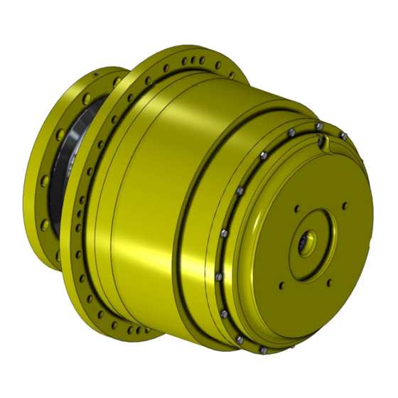
- Page 1 ® Torque-Hub Planetary Final Drive S40B Series Service Manual Rev 09/03/13...
- Page 2 While every precaution has been taken in the preparation of this document, Fairfield Manufacturing Co. Inc. assumes no liability with respect to the use of the documentation described herein, or for any act or omission of Fairfield Manufacturing ® Co. Inc. concerning this documentation. Torque-Hub is a registered trademark of Fairfield Manufacturing Co.
-
Page 3: Table Of Contents
Planetary Final Drive Service Manual Content Introduction Roll and Leak Test Tightening and Torquing Bolts Lubrication Information Disassembly Instructions Main Disassembly Cover Disassembly Housing-Spindle Disassembly Output Carrier Disassembly Input Carrier Disassembly Assembly Instructions Cover Subassembly Input Carrier Subassembly Output Carrier Subassembly Housing-Spindle Subassembly Main Assembly Assembly Drawing... -
Page 4: Introduction
Planetary Final Drive Service Manual Introduction This manual is a step-by-step guide to the disassembly and ® assembly of the S40B SeriesTorque-Hub units with ratios of XX:X or lower. It is designed for the customer or mechanic who is ® repairing this particular Torque-Hub model. -
Page 5: Roll And Leak Test
Planetary Final Drive Service Manual Roll and Leak Test ® Torque-Hub units should always be roll and leak tested before disassembly (if possible) and after assembly to make sure the unit’s gears, bearings and seals are working properly. The following information briefly outlines what to look for when performing these tests. - Page 6 The Leak Test The purpose of a leak test is to make sure the unit is airtight. To perform a leak test, use the leak test fixture from the table on page 10. If the tool is not available, the gearbox must be sealed to perform the test.
-
Page 7: Tightening And Torquing Bolts
Planetary Final Drive Service Manual Tightening and Torquing Bolts If an air impact wrench is used to tighten bolts, extreme care should be taken to ensure the bolts are not tightened beyond their specified torque. The following steps describe how to tighten and torque bolts or socket head cap screws in a bolt circle. -
Page 8: Lubrication Information
95 cst and maintain a minimum viscosity of 40 cst under normal operating conditions. Some applications require special considerations; consult the machine manufacturer and Oerlikon Fairfield for more additional information. The table below lists the recommended viscosities for various ambient operating temperatures. These recommendations are based on temperature rise of 50°... - Page 9 Oil temperatures should be not higher than 160° to 180°F for continuous operation, and no higher than 200°F for intermittent operation. For special applications, high horsepower, high speeds or wide temperature changes, please consult Oerlikon Fairfield. ® Oil Fill Level...
- Page 10 DISASSEMBLY...
- Page 11 THIS PAGE INTENTIONALLY LEFT BLANK...
-
Page 12: Main Disassembly
Planetary Final Drive Service Manual Main Disassembly Perform a roll check and a leak check prior to disassembling the unit. Remove two magnetic Pipe Plugs (14) and drain oil out of gearbox. NOTE: Record the condition and volume of the oil. Remove Bolts (12) from the Cover Subassembly. - Page 13 Remove the Input Sun Gear (6). Remove Input Carrier Subassembly out of the unit. Remove Flanged Bolts (11) from Ring Gear thru Hun Spindle subassembly. Remove the Ring gear (18) off of the Hub-Spindle Subassembly. CAUTION: Safety glasses must be worn during these next steps. Remove Sun Gear (7) from Output Carrier Subassembly.
-
Page 14: Cover Disassembly
Planetary Final Drive Service Manual Cover Disassembly Remove the O-Ring (8) from groove in the Cover Plate (5) and discard it. Remove Thrust Washer (9) from the Thrust Bearing (10). Remove Thrust Bearing (10) from the Thrust Washer (9). Remove Thrust Washer (9) from the groove on the Cover Plate (5). Remove Thrust Washer (17) from the Cover Plate (5). -
Page 15: Housing-Spindle Disassembly
Planetary Final Drive Service Manual Housing-Spindle Disassembly Set the unit on a bench so that the Spindle (1A) flange is down. Continued on Next Page... - Page 16 Remove O-Ring (25) from the Housing (1G) and discard it. Remove Hexagonal Bolts (1J) from Spindle (1A). Remove Bearing Carrier (1P) from the Spindle (1A). CAUTION: The Shim edges are sharp; wear gloves when handling or installing Shims to prevent injury. Remove Steel Shims (1I) from the Internal Coupling (1H).
- Page 17 Remove the Face Seal (1B) from the Housing (1G) and Spindle (1A). Remove outboard Bearing Cone (1D) from the Housing (1G). Using a hammer and punch drive the inboard Bearing Cup (1E) out of the Housing (1G). Be careful not to damage the counter bore in the housing. Turn the Housing (1G) over and drive the outboard Bearing Cup (1C) out of the Housing.
-
Page 18: Output Carrier Disassembly
Planetary Final Drive Service Manual Output Carrier Disassembly Unbend the tang of Lock-Tanged Washer (2I) from the Bearing Nut (2H) and remove the Bearing Nut (2H) from the Planet Shaft (4K). Remove Lock-Tanged Washer (2I) from the Planet Shaft (4K). Remove Lock Pin (2J) from the slot of the Carrier (4A) and Planet Shaft (4K). -
Page 19: Input Carrier Disassembly
Planetary Final Drive Service Manual Input Carrier Disassembly Unbend the tang of Lock-Tanged Washer (2I) from the Bearing Nut (2H) and remove the Bearing Nut (2H) from the Planet Shaft (2K). Remove Lock-Tanged Washer (2I).from the Planet Shaft (2K). Remove Lock Pin (2J) from slot of the Carrier (3A) and Planet Shaft (2K). Remove the Planet Shaft (2K). - Page 20 ASSEMBLY...
-
Page 21: Cover Subassembly
Planetary Final Drive Service Manual Cover Subassembly Place Cover (5) with bore side up on the table. Grease and install Thrust Washer (9) onto Cover (5). The grease should hold washer in place for assembly. Grease and install Bering (10) on top of Thrust Washer (9). Grease and install Thrust Washer (9) on top of Bearing (10). -
Page 22: Input Carrier Subassembly
Planetary Final Drive Service Manual Input Carrier Subassembly CAUTION: Safety glasses must be worn during these next steps. Place Planet Gear (2B) onto press table. Install Retaining Ring (2G) into the groove of the Planet Gear (2B). Apply grease and install Thrust Washer (2E) onto the bore of the Planet Gear (2B) Use Tool T-159309 and install Bearing Cups (2C), with wide face into bore of the Planet Gear (3F). - Page 23 Inspect Planet Shaft (2K) for nicks and burrs. Insure that planet shaft hole and planet shaft are free from debris, burrs, sharp corners. Start the Planet Shaft (3E) on the wide side of the Carrier (2A). Install Planet Shaft (2K) through large diameter in the carrier hole and through planet gear bearing inner race by aligning the lock pin slot in both carrier and planet shaft.
-
Page 24: Output Carrier Subassembly
Planetary Final Drive Service Manual Output Carrier Subassembly CAUTION: Safety glasses must be worn during these next steps. Place Planet Gear (4B) onto press table. Install Internal Retaining Ring (4E) into the groove of Planet Gear (4B). NOTE: In step below insure to install the Spacer (4F) into the deepest bore side from the retaining groove of the Planet Gear (4B). - Page 25 Slide Planet Gear (4B) assembly into planet window of Carrier (2A) with Retaining Ring (4E) towards internal spline. Align planet bore in Planet Gear (4B) with Thrust Washer (2F) bore and Carrier (4A) planet shaft bore. Inspect the Planet Shaft (4K) for nicks and burrs. Insure that the planet shaft hole and Planet Shaft (4K) are free from debris, burrs, and sharp corners.
-
Page 26: Housing-Spindle Subassembly
Planetary Final Drive Service Manual Housing Spindle Subassembly Place Hub (1A) on table such that long hub end is up. Using alcohol and a clean rag, wipe off bearing locations on the Housing (1G) and the Spindle (1A). Press one Bearing Cup (1E) into bearing counter bore of spindle end of housing until seated against shoulder in housing. - Page 27 Ensure there are no nicks or burrs on the installation radius that could damage the seal during installation. Place one half of the Face Seal (1B) into the seal counter-bore of the Spindle (1A). Place one half of the Face Seal (1B) into the seal counter-bore of the Housing (1G). If used install Boot Seal (1U) onto Housing (1G).
- Page 28 Measure depth from the face of the Bearing Plate to the surface of the Shaft. Subtract the average thickness of the Bearing Plate. Add .004 to this difference to get required shim pack thickness. Round the dimension down to get a correct shim pack thickness. CAUTION: The Shim edges are sharp;...
- Page 29 THIS PAGE INTENTIONALLY LEFT BLANK...
-
Page 30: Main Assembly
Planetary Final Drive Service Manual Main Assembly NOTE: Spray component parts with a liberal amount of oil as they are being assembled. Clean the internal threads of Internal Coupling (1H) and of Bolts (28). Lower Output Carrier Subassembly into Internal Coupling (1H), in mesh with the splines. Place Retainer Plate (27) into the groove of the Carrier and onto Internal Coupling (1H). - Page 31 Continued on Next Page Install Cover Sub Assembly onto the Ring Gear (18). Install Bolts (12) through Cover into Ring Gear (18) and torque them to 35-45 ft-lbs. Install Pipe Plugs (14) with thread sealant into Cover. The unit should now be leak and roll checked as per instructions on page 5 and 6. The motor can be reinstalled into the gearbox for the leak check to seal it off, and the unit pressurized through a pipe plug hole on the cover.
-
Page 32: Assembly Drawing
Planetary Final Drive Service Manual Assembly Drawing... -
Page 33: Parts List
Planetary Final Drive Repair Instructions Parts List Number Description SPINDLE FACE SEAL BEARING CUP BEARING CONE BEARING CUP BEARING CONE HOUSING INTERNAL COUPLING STEEL SHIM HEXAGONAL BOLT MAGNETIC PIPE PLUG CARRIER PLANET GEAR BEARING CUP BEARING CONE THRUST WASHER THRUST WASHER INTERNAL RETAINING RING BEARING NUT LOCK-TANGED WASHER... - Page 34 Number Description ID PLATE SCREW DRIVE THRUST WASHER RING GEAR O-RING EXTERNAL RETAINING RING RETAINER PLATE BOLT PIPE PLUG PIPE PLUG MAGNETIC PIPE PLUG PIPE PLUG SEAL BOOT BEARING CARRIER...
-
Page 35: Assembly Tools
Planetary Final Drive Repair Instructions Assembly Tools T125033 – BEARING CUP ASSEMBLY ADAPTOR... - Page 36 T125034 – BEARING CUP ASSEMBLY ADAPTOR...
- Page 37 T164786 – ALIGNMENT PIN FOR ASSEMBLY...
- Page 38 T136699 – .750 DRIVE LOCKNUT WRENCH...
- Page 39 T163327 – SPLINED LOCATOR RING...
- Page 40 T159309 – LOADING PLUG AND BASE FOR ASSEMBLY...
- Page 41 T160835 – ASSEMBLY PRESSING TOOL...
- Page 42 T158152 – LOADING PLUG AND BASE FOR ASSEMBLY...
- Page 43 T158338 – ASSEMBLY PRESSING TOOL...
- Page 44 T147871 – N-12 LOCK NUT WRENCH...
- Page 45 T173814 – LEAK TEST ADAPTOR...
- Page 46 T212150 – ROLL TEST TOOL...
-
Page 47: Contact Information
Fairfield Manufacturing Co. Inc. U.S. 52 South / P.O. Box 7940 Lafayette IN 47903-7940 Shipping Address 2309 Concord Road Lafayette, IN 47909 Main (765) 772-4001 Applications Engineering (765) 772-4011 Sales and Service (765) 772-4010 E-mail Applications Engineering apps@fairfieldmfg.com Sales sales@fairfieldmfg.com Website www.oerlikon.com/fairfield... - Page 48 Oerlikon Fairfield U.S. 52 South / P.O. Box 7940 Lafayette, IN 47903 USA 765-772-4000 www.oerlikon.com/fairfield...
Need help?
Do you have a question about the Fairfield Torque-Hub S40B Series and is the answer not in the manual?
Questions and answers