Table of Contents
Advertisement
Model-Based Design Toolbox
MPC57xx Series
Quick Start Guide
An Embedded Target for the MPC57xx Family of Processors
Version 3.0.0
Target Based Automatic Code Generation Tools
For MATLAB™/Simulink™/Stateflow™ Models working with Simulink Coder ™ and Embedded Coder
®
© 2019 NXP Semiconductors. All rights reserved
Advertisement
Table of Contents

Subscribe to Our Youtube Channel
Related Manuals for NXP Semiconductors MPC57 Series


Summary of Contents for NXP Semiconductors MPC57 Series
- Page 1 MPC57xx Series Quick Start Guide An Embedded Target for the MPC57xx Family of Processors Version 3.0.0 Target Based Automatic Code Generation Tools For MATLAB™/Simulink™/Stateflow™ Models working with Simulink Coder ™ and Embedded Coder ® © 2019 NXP Semiconductors. All rights reserved...
-
Page 2: Table Of Contents
Summary Installation .......................... 1-3 System Requirements ....................1-3 Installation Steps ......................1-3 1.2.1 Run Add-on installer .................... 1-4 1.2.2 License Registration & Installation ..............1-7 1.2.3 Setting up the Target Compilers ................1-8 1.2.4 Setting the Path for Model-Based Design Toolbox ..........1-8 Run Models ........................ -
Page 3: Installation
1 Installation Installing the Model-Based Design Toolbox is the first step in setting up and running automatic C code generation from MATLAB/Simulink for NXP’s embedded target processors and development boards. 1.1 System Requirements For a flowless development experience the minimum recommended PC platform is: •... -
Page 4: Run Add-On Installer
1.2.1 Run Add-on installer Install the NXP’s Model-Based Design Toolbox by double clicking the *.mltbx file. This will activate the MATLAB Add-ons installer that will automatically start the installation process. After the MATLAB opens, you will be prompted with the following options: 1. - Page 5 3. Click “OK” to start the MATLAB installation process. The rest of the process is silent and under MATLAB control. All the files will be automatically copied into default Add-Ons folder within the MATLAB The default location can be changed prior to installation by changing the Add-Ons path from MATLAB Preferences 4.
- Page 6 6. NXP’s Model-Based Design Toolbox documentation, help and examples are fully integrated with MATLAB development environment. Get more details by accessing the standard Help and Supplemental Software section Model Based Design Toolbox MPC57xx Series Quick Start Guide...
-
Page 7: License Registration & Installation
1.2.2 License Registration & Installation The NXP’s Model Based Design Toolbox is available free of charge, however, a license is required. If you need to get a license it can be obtained by following the path outlined below. encounter issues getting license please... -
Page 8: Setting Up The Target Compilers
1.2.3 Setting up the Target Compilers The target compiler for Model-Based Design Toolbox needs to be configured. Use the notation below to setup these compiler environmental variables. Ensure a system environment variable called <COMPILER_STRING>_TOOL, corresponding to the compiler(s) you have installed, is defined to compiler path value as shown below: S32DS_PA_TOOL = {Toolbox installation path}/tools or {S32 Design Studio installation path}/... - Page 9 >> mbd_mpc_path Treating 'C:\Users\xxxxx\Documents\MATLAB\Add- Ons\Toolboxes\NXP_MBDToolbox_MPC57xx\code' as MBD Toolbox installation root. MBD Toolbox path prepended. Successful. >> Model Based Design Toolbox MPC57xx Series Quick Start Guide...
-
Page 10: Run Models
2 Run Models 2.1 Examples Library & Help NXP’s Model Based Design Toolbox comes with an Examples Library collection that let you test different MCU on-chip modules and run complex applications. The Examples Library mbd_mpc574x_examples.mdl can be opened from “{Model Based Design Install Directory}\MPC_Examples\”... - Page 11 Model Based Design Toolbox MPC57xx Series 2-11 Quick Start Guide...
-
Page 12: Hardware Setup
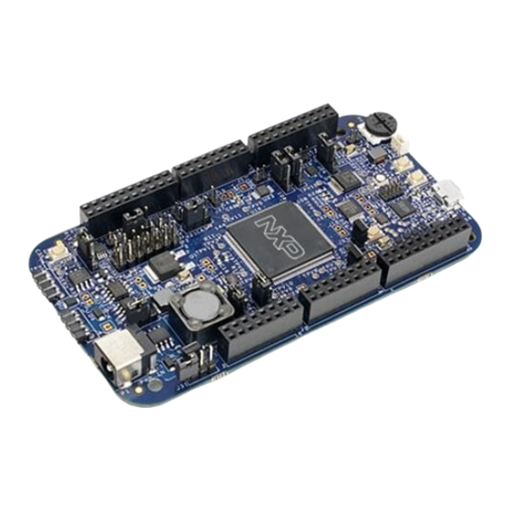
2.2 Hardware Setup All examples provided with the Model-Based Design Toolbox were developed on DEVKIT- MPC5744P as primary target. Additional information about this development kit can be found on NXP official web page here. Before running any example on the DEVKIT-MPC5744P a proper communication setup between the board and the host PC must be enabled. -
Page 13: Bootloader Setup
4. When powered through USB, LEDs DS1, DS2 and DS5 should light green; 2.3 BootLoader Setup To be able to download the applications from MATLAB/Simulink to the target we need to program a special application called RBF into the MCU flash memory. For the first time programming you need to have the S32 Design Studio for PA IDE installed. - Page 14 3. Click on the C/C++ Application Browse button to navigate to the {Model-Based Design Toolbox installation folder}\code\tools\BootLoader\ RBF_Files and choose the appropriate RBF image to be flashed on your setup. Note: each file contains in its name the interfaces allowed for Flash Tool download communication.
- Page 15 4. Configure the Debugger interface to connect with the target. Model Based Design Toolbox MPC57xx Series 2-15 Quick Start Guide...
- Page 16 5. Click on Flash button to start the flash programming sequence. The debugger will connect with the target selected and will start to flash the RBF image into the non- volatile memory of the target. At this point the target should be ready for receiving applications from MATLAB/Simulink environment over the UART interface connected via OpenSDA.
-
Page 17: Hello World Example
2.4 Hello World Example If the hardware and BootLoader setup is completed successful and a virtual COM port is created and visible in Control Panel -> Device Manager -> Port (COM & LPT), then all requirements for running a Model-Based Design Toolbox for MPC57xx Examples are fulfilled. - Page 18 Model Based Design Toolbox MPC57xx Series 2-18 Quick Start Guide...
- Page 19 Follow the next steps to run the example: 1. Double click on MBD_MPC574x_Config_Information block and setup the Download Config parameters according with your PC and HW setup 2. Apply and close this window. Model Based Design Toolbox MPC57xx Series 2-19 Quick Start Guide...
- Page 20 3. Press Build Model button and wait until the code is generated, compiled and downloaded to the evaluation board. 4. Wait until the application is built and the following message is displayed on the screen. Press the board reset button SW3 and then (within 5 seconds) press the OK button to start the application programming to the target.
- Page 21 8. Press the reset button on the evaluation board. 9. The MPC5744P MCU sends “Hello World!!! Press RESET to see this msg again” message over the UART and the UART terminal should display it. Congradulations! You succedded with running your first example created with Model-Based Design Toolbox for MPC57xx Model Based Design Toolbox MPC57xx Series 2-21...
- Page 22 Reg. U.S. Pat. & Tm. Off. Flexis and Processor Expert are trademarks of NXP Semiconductor, Inc. All other product or service names are the property of their respective owners ©2019 NXP Semiconductors. All rights reserved. © 2019 NXP Semiconductors. All rights reserved...
Need help?
Do you have a question about the MPC57 Series and is the answer not in the manual?
Questions and answers