Table of Contents
Advertisement
Advertisement
Table of Contents

Related Manuals for Paladon PNS Series

Summary of Contents for Paladon PNS Series
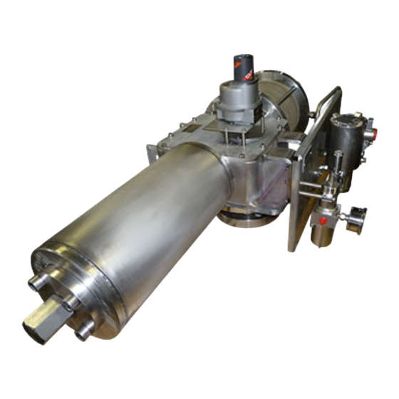
- Page 1 INSTALLATION, COMMISSIONING & MAINTENANCE MANUAL PNS, PND & PNC-Series Pneumatic Scotch-Yoke Valve Actuators Doc/Rev. Description Pages Date Issued By Approved By Q066 R 10 Revision 15.05.12 Q066 R 11 Revision 01.11.13 Q066 Rev : Issued : 01/11/13 Page : 1 of 25...
-
Page 2: Table Of Contents
Contents Page Introduction ......................3 Inspection Requirements on Initial Receipt of Actuator ..........3 Storage Requirements ....................3 Short-Term Storage ..................3 Long-Term Storage ................... 3 Actuator Overview ......................3 Standard Components ..................4 4.1.1 Frame ....................4 4.1.2 Pneumatic Cylinder ................4 4.1.3 End Stop Screws ................. -
Page 3: Introduction
Introduction This manual is designed to allow a qualified user to install, commission and maintain Paladon Systems Ltd PNS, PND and PNC Series valve actuators. This manual should be used in conjunction with any additional documentation supplied at the time of shipping. -
Page 4: Standard Components
Standard Components 4.1.1 Frame The frame contains the scotch-yoke mechanism which converts the linear movement of the pneumatic piston into a quarter-turn rotary movement. To protect personnel from injury and the scotch-yoke mechanism from corrosion, the frame is a fully enclosed carbon steel fabricated construction. To support the transverse forces generated by scotch-yoke mechanisms, and to ensure correct alignment of the piston rod, sliding blocks and yoke bushing, the body also contains a chromium plated guide bar. -
Page 5: Model Number Designations
Stem adapter mounting using an adapter and coupling joint. Paladon Systems Ltd actuators can be mounted in any orientation; however, it is common industry practice to align the centreline of the actuator’s pneumatic cylinder with that of the valve pipework. -
Page 6: Adjusting Open And Closed Valve Positions
Thoroughly clean all mounting flanges, taking special care to ensure that all grease is removed. To assist with assembly, lubricate the valve stem with suitable oil or grease. Lift the actuator by its lifting eyes and, if possible, ensure that the valve stem is in the vertical position. -
Page 7: Preparations For Start-Up
Check valve position and repeat steps 2 to 4 until desired valve position is reached. Tighten the protective nut on the applicable end stop screw. Repeat steps 8.2 to 8.6 for the remaining end stop screw. Preparations for Start-Up Pneumatic Connections & Considerations Prior to connecting the pneumatic supply line(s), check that all pipes and fittings are in accordance with the plant specifications. -
Page 8: Double-Acting Actuator With Handpump Type Manual Override
Once the desired valve position has been achieved, disengage the manual override by moving the lever on the handwheel frame mounting flange to the ‘DISENGAGED’ position. Re-connect pneumatic supply connections. 10.2 Double-Acting Actuator with Handpump Type Manual Override (See Section 16.8, Dwg. HYX-XXX-CYXXX-00-002-PL) Isolate pneumatic supply, depressurise actuator and control system. -
Page 9: Maintenance
Open the handpump stop valve by rotating its handle anti-clockwise. Maintenance 11.1 All Paladon Systems Ltd actuators have been designed to provide long service with minimum maintenance; however, a preventative maintenance program is recommended. Preventative maintenance programs not only help avoid unanticipated and costly down time, but also typically reduce the overall cost of ownership. - Page 10 12.6 Loosen the tie rods (see Section 16.3, Dwg. PNX-XXX-CYXXX-00-001-PL, Item 6 – manufactured part). 12.7 Unscrew the piston rod and slide it off (see Section 16.3, Dwg. PNX-XXX- CYXXX-00-001-PL, Item 3 – manufactured part). 12.8 Unscrew the frame fixing screws (see Section 16.3, Dwg. PNX-XXX-CYXXX-00- 001-PL, Item 9 –...
-
Page 11: Lubrication
Lubrication Usually it is not necessary to lubricate the actuator as all moving parts are lubricated for life; however, in the unlikely event that additional lubrication is required, the following lubricant should be used: Manufacturer AGIP Trade Name AGIP GR MU EP Colour Yellow/Brown Oil Type... -
Page 12: Trouble-Shooting
Trouble-Shooting In the unlikely event of incorrect actuator operation, please refer to the below trouble-shooting guide. Fault Cause Corrective Action Erratic or slow operation Supply pressure erratic or Check supply pressure and below minimum specified correct as required. pressure. Worn components. Disassemble and visually inspect parts for obvious wear and tear, and replace as... -
Page 13: Drawings
Drawings Section Drawing Description 16.1 XXX-XXX-FRXXX-00-001-PL Frame Assembly with symmetrical scotch- yoke mechanism 16.2 XXX-XXX-FRXXX-00-002-PL Frame Assembly with demi-canted scotch- yoke mechanism 16.3 PNX-XXX-CYXXX-00-001-PL Pneumatic Cylinder Assembly 16.4 XXX-XXX-SRXXX-00-001-PL Spring Cylinder Assembly (one spring for low spring stroke torques) 16.5 XXX-XXX-SRXXX-00-002-PL Spring Cylinder Assembly (three springs for high spring stroke torques) -
Page 14: Xxx-Xxx-Frxxx-00-001-Pl
16.1 XXX-XXX-FRXXX-00-001-PL Q066 Rev : Issued : 01/11/13 Page : 14 of 25... -
Page 15: Xxx-Xxx-Frxxx-00-002-Pl
16.2 XXX-XXX-FRXXX-00-002-PL Q066 Rev : Issued : 01/11/13 Page : 15 of 25... -
Page 16: Pnx-Xxx-Cyxxx-00-001-Pl
16.3 PNX-XXX-CYXXX-00-001-PL Q066 Rev : Issued : 01/11/13 Page : 16 of 25... -
Page 17: Xxx-Xxx-Srxxx-00-001-Pl
16.4 XXX-XXX-SRXXX-00-001-PL Q066 Rev : Issued : 01/11/13 Page : 17 of 25... -
Page 18: Xxx-Xxx-Srxxx-00-002-Pl
16.5 XXX-XXX-SRXXX-00-002-PL Q066 Rev : Issued : 01/11/13 Page : 18 of 25... -
Page 19: Hyx-Xxx-Hdxxx-00-001-Pl
16.6 HYX-XXX-HDXXX-00-001-PL Q066 Rev : Issued : 01/11/13 Page : 19 of 25... -
Page 20: Xxx-Xxx-Shxxx-00-001-Pl
16.7 XXX-XXX-SHXXX-00-001-PL Q066 Rev : Issued : 01/11/13 Page : 20 of 25... -
Page 21: Hyx-Xxx-Cyxxx-00-002-Pl
16.8 HYX-XXX-CYXXX-00-002-PL Q066 Rev : Issued : 01/11/13 Page : 21 of 25... -
Page 22: Pnx-Xxx-Cyxxx-00-002-Pl
16.9 PNX-XXX-CYXXX-00-002-PL Q066 Rev : Issued : 01/11/13 Page : 22 of 25... -
Page 23: Spares Kit Ordering & Additional Service Support
Actuator Serial Number (6 or 7 digit number with a RFPL prefix) Paladon Contract Number (5 digit number with an ACCP, ACE, ACP, ACSP, CCP, CE, CGH, CP, CPC or CSP prefix) General Arrangement or Control Schematic Drawing Number ... -
Page 24: Functional Safety Data
Functional Safety Data PNL / HYL HY/DG Actuator actuator actuator Parameter name Symbol Equation / source Proof Test Interval 8760 8760 8760 Type A/B type A type A type A type A Total failures: From FMEA 2.14E-06 1.30E-06 8.48E-07 ... -
Page 25: 18.2 Normal Operating Condition
18.2 Normal Operating condition: Under no fault (normal) conditions the PN, HY and DG scotch yoke actuators behave as follows: a) Correct pressure is supplied the pneumatic/hydraulic module; this forces the piston rod to move linearly; operating the yoke assembly. The scotch yoke assembly will then continue the movement of the piston rod which will compress the spring module.
Need help?
Do you have a question about the PNS Series and is the answer not in the manual?
Questions and answers