
Related Manuals for Mannesmann Rexroth Indramat ECODRIVE DKC01.1

Summary of Contents for Mannesmann Rexroth Indramat ECODRIVE DKC01.1
- Page 1 engineering mannesmann Rexroth ECODRIVE DKC01.1/DKC11.1 Drive Controllers Project Planning Manual DOK-ECODRV-DKC01/11.1*-PRJ3-EN-P Indramat 270950 Buy: www.ValinOnline.com | Phone: 844-385-3099 | Email: CustomerService@valin.com...
- Page 2 About this documentation ECODRIVE DKC01.1/DKC11.1 Drive Controllers ECODRIVE DKC01.1/DKC11.1 Drive Controllers Title Project Planning Type of document DOK-ECODRV-DKC01/11.1*-PRJ3-EN-P Document code • 209-0069-4390-03 Internal file reference Editing sequence Document identification of Date Remark previous editions 209-0069-4390-00 EN/05.96 May 96 First edition 209-0069-4390-01 EN/06.96 June 96 Revision...
- Page 3 ECODRIVE DKC01.1/DKC11.1 Drive Controllers About this documentation It supplies information on: What is this documentation for? • planning the mechanical control cabinet • planning the electrical system in the control cabinet • logistic handling of the equipment • preparing the resources for start-up "ECODRIVE DKC Servo Drives with MKD"...
- Page 4 About this documentation ECODRIVE DKC01.1/DKC11.1 Drive Controllers Notes DOK-ECODRV-DKC01/11.1*-PRJ3-EN-P Buy: www.ValinOnline.com | Phone: 844-385-3099 | Email: CustomerService@valin.com...
-
Page 5: Table Of Contents
ECODRIVE DKC01.1/DKC11.1 Drive Controllers Table of contents Table of contents 1 Introduction to the system 1.1 Application features..........................1-1 1.2 Overview of the functions........................1-1 2 Safety instructions for electrical drives 2.1 General ..............................2-1 2.2 Protection against contact with electrical parts ..................2-2 2.3 Protection against shocks caused by safety extra-low voltage (SELV)......... - Page 6 Table of contents ECODRIVE DKC01.1/DKC11.1 Drive Controllers 5 BZM auxiliary bleeder module 5.1 Dimensioning the components relevant for regeneration ..............5-1 5.2 Dimensional data and installation dimensions ..................5-5 5.3 Technical data............................5-6 5.4 Front view............................. 5-6 5.5 Electrical connections .......................... 5-7 5.6 Type code and rating plate........................
- Page 7 ECODRIVE DKC01.1/DKC11.1 Drive Controllers Table of contents 11 Power connection 11-1 11.1 Direct power connection........................11-1 11.2 Line contactor/fuse protector ......................11-2 Calculating the phase current at the power connection .............. 11-2 Selecting fuse protector Q1 and line contactor K1..............11-3 11.3 Control circuit to the power connection....................
- Page 8 Table of contents ECODRIVE DKC01.1/DKC11.1 Drive Controllers Notes DOK-ECODRV-DKC01/11.1*-PRJ3-EN-P Buy: www.ValinOnline.com | Phone: 844-385-3099 | Email: CustomerService@valin.com...
-
Page 9: Introduction To The System
ECODRIVE DKC01.1/DKC11.1 Drive Controllers Introduction to the system Introduction to the system Application features The drive system with the ECODRIVE drive controllers is the most cost- effective solution offering the highest functionality for almost any field of application in which translatory or rotary motions are to be automated. Outstanding performance data, an extensive range of functions as well as an excellent price-to-performance ratio represent the salient features of this drive system. - Page 10 Introduction to the system ECODRIVE DKC01.1/DKC11.1 Drive Controllers Servodrive with integrated position control SPS-Control DKC01.1Drive controller AC-servo motor with POSITIONING-interface ® MS-DOS - PC Parameters Diagnosis Operating data RS 232 RS 485 Drive processor I/O _ card Stored Fine interpolation Selection positioning of the...
- Page 11 ECODRIVE DKC01.1/DKC11.1 Drive Controllers Introduction to the system Servodrive with analog speed interface and integrated actual position detection AC servo motor Control unit DKC01.1 or DKC11.1 drive with position control controller with ANALOG interface ® MS-DOS - PC Parameters Diagnosis Parameters Operating data Diagnosis...
- Page 12 Introduction to the system ECODRIVE DKC01.1/DKC11.1 Drive Controllers Servodrive with stepper interface Control unit DKC01.1 drive controller AC servo motor with step pulse generation with STEPPER interface ® MS-DOS - PC Interpolation Parameters Diagnosis Operating data RS 232 RS 485 Drive processor forwards Stepper...
- Page 13 ECODRIVE DKC01.1/DKC11.1 Drive Controllers Introduction to the system Servodrive with electronic gearbox function AC-Servomotor Servodrive DKC01.1 with electronic gearbox function ® MS-DOS - PC Parameters Diagnosis Operating data RS 232 RS 485 Drive processor Lead axis Step motor electronic gearbox transmitter interface Lead axis...
- Page 14 Introduction to the system ECODRIVE DKC01.1/DKC11.1 Drive Controllers Notes DOK-ECODRV-DKC01/11.1*-PRJ3-EN-P Buy: www.ValinOnline.com | Phone: 844-385-3099 | Email: CustomerService@valin.com...
-
Page 15: Safety Instructions For Electrical Drives
ECODRIVE DKC01.1/DKC11.1 Drive Controllers Safety instructions for electrical drives Safety instructions for electrical drives Please read the following instructions carefully before initial startup. These safety instructions must be observed at all times. If the product is transferred to a third-party, the safety instructions must be included. -
Page 16: Protection Against Contact With Electrical Parts
Safety instructions for electrical drives ECODRIVE DKC01.1/DKC11.1 Drive Controllers • Technical specifications as well as the connection and installation re- quirements can be found in the product documentation and must be observed under all circumstances. Protection against contact with electrical parts Note: Only relevant for devices and drive components with voltages ex- ceeding 50 volts. -
Page 17: Protection Against Shocks Caused By Safety Extra-Low Voltage (Selv)
ECODRIVE DKC01.1/DKC11.1 Drive Controllers Safety instructions for electrical drives High discharge current! Danger to life or risk of bodily injury! ⇒ All units and the motors must first be connected to a grounding point with the ground wire or must be WARNING grounded themselves before switching on power. -
Page 18: Protection Against Dangerous Movements
Safety instructions for electrical drives ECODRIVE DKC01.1/DKC11.1 Drive Controllers Protection against dangerous movements Dangerous movements can be caused if the connected motors are not controlled correctly. There are various causes of dangerous movements: • faulty wiring or cable connections • operating the components improperly •... - Page 19 ECODRIVE DKC01.1/DKC11.1 Drive Controllers Safety instructions for electrical drives Dangerous movements! Danger may result in equipment damage, personal injury or death! ⇒ Personal safety must be ensured by higher-level, DANGER monitoring at the installation or precautionary meas- ures for the reasons listed above. These are provided by the plant manufacturer according to the specific conditions of the plant based on a danger and mal- function analysis.
-
Page 20: Protection Against Magnetic And Electromagnetic Fields During Operation And Assembly
Safety instructions for electrical drives ECODRIVE DKC01.1/DKC11.1 Drive Controllers Protection against magnetic and electromagnetic fields during operation and assembly Magnetic and electromagnetic fields near current-carrying conductors and permanent magnets pose a serious health hazard for persons with pace- makers, metal implants and hearing aids. Health hazard for persons with pacemakers, metal implants and hearing aids in the immediate vicinity of electrical equipment. -
Page 21: Protection During Handling And Assembly
ECODRIVE DKC01.1/DKC11.1 Drive Controllers Safety instructions for electrical drives Protection during handling and assembly Handling or assembling drive components improperly may lead to per- sonal injury. Risk of injury due to improper handling! Bodily injury may be caused by crushing, shearing, cut- ting, and pounding forces. - Page 22 Safety instructions for electrical drives ECODRIVE DKC01.1/DKC11.1 Drive Controllers Notes DOK-ECODRV-DKC01/11.1*-PRJ3-EN-P Buy: www.ValinOnline.com | Phone: 844-385-3099 | Email: CustomerService@valin.com...
-
Page 23: Selecting The Components
ECODRIVE DKC01.1/DKC11.1 Drive Controllers Selecting the components Selecting the components Overview of the required components System voltage Mains filter for power connections Transformer Fuse Mains filter for power supply unit Mains contactor Power supply unit Drive controller Auxiliary bleeder module DC 24 V Firmware Auxiliary capacitance... -
Page 24: Selection Procedure
Selecting the components ECODRIVE DKC01.1/DKC11.1 Drive Controllers Selection procedure ⇒ Dimension the drive according to how it is to be used. A document for Dimensioning and selecting the servo drive this is under preparation. ⇒ Select motor/drive combination (DKC + MKD) using the "Selection Data"... -
Page 25: Compiling The Required Data
ECODRIVE DKC01.1/DKC11.1 Drive Controllers Selecting the components Compiling the required data Designation Symbol Values/Units Effective load torque ......in Nm Acceleration torque ......in Nm Operating torque BEARB ......in Nm Motor speed used NUTZ ......in min-1 Load moment of inertia LAST ...... - Page 26 Selecting the components ECODRIVE DKC01.1/DKC11.1 Drive Controllers Notes DOK-ECODRV-DKC01/11.1*-PRJ3-EN-P Buy: www.ValinOnline.com | Phone: 844-385-3099 | Email: CustomerService@valin.com...
-
Page 27: Ecodrive Dkc Drive Controllers
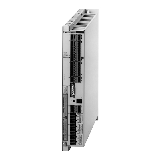
ECODRIVE DKC01.1/DKC11.1 Drive Controllers ECODRIVE DKC drive controllers ECODRIVE DKC drive controllers Hardware View of unit DKC**.*-030-3-FW DKC**.*-040-7-FW = 30 A) = 40 A) Mains connection Mains connection AC (380...460) V 1 x AC 230 V oder 3 x AC 230 V Intermediate circuit connection BZM auxiliary bleeder module CZM auxiliary capacitance module... -
Page 28: Dimensional Sheets And Installation Dimensions
ECODRIVE DKC drive controllers ECODRIVE DKC01.1/DKC11.1 Drive Controllers Dimensional sheets and installation dimensions distance to adjacent unit min. 80 mm 32,5 M6 in mounting panel cooling air outlet min. 80 mm cooling air inlet MB0201.fh5 Fig. 4-2: Dimensional data and install ation dimensions DKC01.1-030-3-FW DOK-ECODRV-DKC01/11.1*-PRJ3-EN-P Buy: www.ValinOnline.com | Phone: 844-385-3099 | Email: CustomerService@valin.com... - Page 29 ECODRIVE DKC01.1/DKC11.1 Drive Controllers ECODRIVE DKC drive controllers distance to adjacent unit 32.5 min. 80 mm M6 in mounting panel cooling air outlet min. 80 mm cooling air inlet MB0202.fh5 Fig. 4-3: Dimensional data and installation dimensions DKC01.1-040-7- FW/DKC11.1-040-7-FW DOK-ECODRV-DKC01/11.1*-PRJ3-EN-P Buy: www.ValinOnline.com | Phone: 844-385-3099 | Email: CustomerService@valin.com...
-
Page 30: Technical Data
ECODRIVE DKC drive controllers ECODRIVE DKC01.1/DKC11.1 Drive Controllers Technical data Power connection / Power section Symbol Unit DKC01.1-030-3-FW DKC**.1-040-7-FW Designation Operating mode at the mains single-phase three-phase three-phase Mains input voltage 1 x AC 230 3 x AC 230 3 x AC ±... - Page 31 ECODRIVE DKC01.1/DKC11.1 Drive Controllers ECODRIVE DKC drive controllers Additional connection of the DC24 power supply The DKC drives should be firmly connected to the DC24V power supply; preferred method Fig. 4-6 They can also be connected to the DC24V power supply in a switchable manner Fig.
- Page 32 ECODRIVE DKC drive controllers ECODRIVE DKC01.1/DKC11.1 Drive Controllers Ambient and installation conditions Selection lists are specified for each motor/drive documentation. Please Ambient temperature and installation altitude refer to the documentation "ECODRIVE Servodrives DKC with MKD - Selection Lists - The selection lists apply within the given ambient and installation condi- tions (see Fig.
-
Page 33: Type Code And Rating Plate
ECODRIVE DKC01.1/DKC11.1 Drive Controllers ECODRIVE DKC drive controllers Type code and rating plate DKC 01.1 - 040 - 7 - FW Example: Type code fields: Drive controller Series Version Type 30 A 40 A Rated intermediate circuit voltage 300 V 700 V Firmware A firmware specifying the functions of the... -
Page 34: Firmware
ECODRIVE DKC drive controllers ECODRIVE DKC01.1/DKC11.1 Drive Controllers Firmware The firmware located in the drive controller determines the functional features of the ECODRIVE drive controller. The firmware "FWA-ECODRV-ASE-02VRS-MS" is for the drive control- lers DKC01.1-*** and DKC11.1-***. The firmware has its own order number. This means that it is always pos- sible to order the identical firmware version. -
Page 35: An Overview Of The Electrical Connections
ECODRIVE DKC01.1/DKC11.1 Drive Controllers ECODRIVE DKC drive controllers An overview of the electrical connections Front view with supply terminals RS 232 serial RS 485+ RS 485 serial RS 485- interface interface Shield Go to zero point POS1/SM1+ Positioning record Zero switch POS2/SM1- POS3/SM2+ LIMIT+... -
Page 36: Overall Connection Diagrams
4-10 ECODRIVE DKC drive controllers ECODRIVE DKC01.1/DKC11.1 Drive Controllers Overall connection diagrams DKC01.1 drive controller in operating mode POSITIONING interface contr. volt. for DKC +24V drive enable RS 232- start signal AH/Start interface zero ref. to contr. volt. ready to RS485+ RS485+ RS 485-... - Page 37 4-11 ECODRIVE DKC01.1/DKC11.1 Drive Controllers ECODRIVE DKC drive controllers DKC01.1 drive controller in operating mode ANALOG interface contr. volt. for DKC +24V drive enable RS 232- start signal AH/Start interface zero ref. to contr. volt. ready to RS485+ RS485+ RS 485- operate interface RS485-...
- Page 38 4-12 ECODRIVE DKC drive controllers ECODRIVE DKC01.1/DKC11.1 Drive Controllers DKC011.1 drive controller with ANALOG interface contr. volt. for DKC +24V drive enable RS 232- start signal AH/Start interface zero ref. to contr. volt. ready to RS485+ RS485+ RS 485- operate interface RS485- RS485-...
- Page 39 4-13 ECODRIVE DKC01.1/DKC11.1 Drive Controllers ECODRIVE DKC drive controllers DKC01.1 drive controller in operating mode STEP MOTOR interface +24V contr. volt. for DKC drive enable RS 232- AH/Start start signal interface zero ref. to contr. volt. ready to RS485+ RS485+ RS 485- operate RS485-...
-
Page 40: Electrical Connection To The Supply Terminal Strips
4-14 ECODRIVE DKC drive controllers ECODRIVE DKC01.1/DKC11.1 Drive Controllers Electrical connection to the supply terminal strips The description of the electrical connections below are first grouped ac- cording to numbers of the supply terminal strips (e.g. X1, X2 etc.) and then according to the functions. - Page 41 4-15 ECODRIVE DKC01.1/DKC11.1 Drive Controllers ECODRIVE DKC drive controllers The RS-485 interface is needed for programming, parameterizing and di- RS-485 interface agnosis during startup operation and service procedures. The RS 485 interface allows : • the implementation of a serial bus with up to 31 stations connected by means of a twisted pair cable (half duplex mode), •...
- Page 42 4-16 ECODRIVE DKC drive controllers ECODRIVE DKC01.1/DKC11.1 Drive Controllers The converter can be modified for various peripherals by using specific Switch position in the interface switch positions. converter The switch positions shown below must be used strictly for the following wiring diagrams.
- Page 43 4-17 ECODRIVE DKC01.1/DKC11.1 Drive Controllers ECODRIVE DKC drive controllers The interface converter must be connected via the D-SUB male connec- Connecting the RS-232 of the tor because of the effects of interference. PCs to the interface converter Interface converter PSM-EG-RS232/RS485-P/2D RS232 TxD (2) RxD (2)
-
Page 44: X2 Positioning Or Stepper Interface
4-18 ECODRIVE DKC drive controllers ECODRIVE DKC01.1/DKC11.1 Drive Controllers X2 positioning or stepper interface Note: Does not apply to the DKC11.1-040-FW! The cables for the control inputs and status reports required for both the POSITIONING interface and the stepper interface are connected to the X2/(13-24) supply terminals. - Page 45 4-19 ECODRIVE DKC01.1/DKC11.1 Drive Controllers ECODRIVE DKC drive controllers Control inputs for jog mode max. 20 m Positive jog 0,5 mm HIGH LIMIT+ Negative jog 0,5 mm LIMIT- HIGH JOG+ JOG- INREF INBWG INPOS 0 V ext Inputs: Input voltage min.
- Page 46 4-20 ECODRIVE DKC drive controllers ECODRIVE DKC01.1/DKC11.1 Drive Controllers Status reports max. 20 m LIMIT+ LIMIT- JOG+ 0,5 mm JOG- Path control point Homing in INREF Movement in INBWG Position in INPOS 0 V ext Outputs: Output voltage min. max. HIGH 16 V ext.
- Page 47 4-21 ECODRIVE DKC01.1/DKC11.1 Drive Controllers ECODRIVE DKC drive controllers Positioning interface Positioning signals and outputs max. 20 m for acknowledging the positioning signals POS1 POS2 POS3 dig. POS4 POS5 POS Q1 POS Q2 POS Q3 POS Q4 POS Q5 0 V ext 0,5 mm Inputs: Input voltage...
- Page 48 4-22 ECODRIVE DKC drive controllers ECODRIVE DKC01.1/DKC11.1 Drive Controllers Note: If the inputs POS 1 and POS 2 in Fig. 4-28 are assigned a LOW signal, 5 volts are applied there. If a PLC is connected, this can cause the control LEDs to respond. This is prevented by an interconnected blocking diode in accordance with the circuit proposal Fig.
- Page 49 4-23 ECODRIVE DKC01.1/DKC11.1 Drive Controllers ECODRIVE DKC drive controllers • Logical 1 is recognized if a positive differential voltage is applied from Control with differential signals SM+ to SM-. • Logical 0 is recognized if a negative differential voltage is applied from SM+ to SM-.
- Page 50 4-24 ECODRIVE DKC drive controllers ECODRIVE DKC01.1/DKC11.1 Drive Controllers Dimensioning the pull-up resistors (2k4 resistors in Fig. 4-32 depends on Single-channel control via npn the load capability (current, power dissipation) of the open-collector out- – open-collector outputs (NPN) puts of the control. Note: Controlling the stepper interface with differential signals is preferable to single-channel control as the noise immunity of...
-
Page 51: X3 Analog Inputs And Outputs
4-25 ECODRIVE DKC01.1/DKC11.1 Drive Controllers ECODRIVE DKC drive controllers X3 analog inputs and outputs The inputs and outputs for operating the analog interfaces are connected via the supply terminal X3/(1-8). • torque reduction • setpoint input • diagnostics outputs • override function for positioning control The actual position is output either as an incremental, parallel or absolute value serial via the X3/(9-16) supply terminal. - Page 52 4-26 ECODRIVE DKC drive controllers ECODRIVE DKC01.1/DKC11.1 Drive Controllers Torque reduction max. 20 m +10V 0,5 mm IRED 1 0,5 mm IRED 2 Inputs: Input voltage min. max. ± 10 V ± 15 V between IRED1-IRED2 ± 10 V ± 15 V between IRED1-0V;...
- Page 53 4-27 ECODRIVE DKC01.1/DKC11.1 Drive Controllers ECODRIVE DKC drive controllers Actual position value 360° electric = one cycle Square-wave pulse looking onto motor shaft and with clockwise rotation t1 < 50 ns SV0201.fh5 Fig. 4-36: Signals for the incremental actual position value ou tput max.
- Page 54 4-28 ECODRIVE DKC drive controllers ECODRIVE DKC01.1/DKC11.1 Drive Controllers Recommended input circuit for C N C secondary electronics RS-422 DIN 66 259, sec. 3 = 120 W Recommended differential line receiver AM 26 LS 32 MC 3486 SN 75 ALS 193 SN 75 ALS 195 AP0201.fh5 Fig.
-
Page 55: X4 Terminals For The Control Circuit
4-29 ECODRIVE DKC01.1/DKC11.1 Drive Controllers ECODRIVE DKC drive controllers Actual value position SSI max. 20 m format 0.5 mm Data+ Positioning Data- interface CLK+ -absolute- CLK- 0 V ext RS422 compatible differential outputs: Output voltage min. max. HIGH 2.5 V 0.8 V Output current I max. -
Page 56: X5, X6, X7 Motor Connections
4-30 ECODRIVE DKC drive controllers ECODRIVE DKC01.1/DKC11.1 Drive Controllers X5, X6, X7 motor connections For the terminal connection assignments to the motor connections, refer to the overall connection diagram in Fig. 4-15. For further information, please see the documentation "ECODRIVE ser- vomotors MKD"... -
Page 57: Bzm Auxiliary Bleeder Module
ECODRIVE DKC01.1/DKC11.1 Drive Controllers BZM auxiliary bleeder module BZM auxiliary bleeder module Dimensioning the components relevant for regeneration For each servo-technical application, it is necessary to check whether the • continuous regenerative power • peak regenerative power • regenerative energy needed for the application can be sufficiently absorbed by the bleeder (brake resistance). - Page 58 BZM auxiliary bleeder module ECODRIVE DKC01.1/DKC11.1 Drive Controllers 1 DKC + BZM 1. Continuous regenerative power ≤ BD, DKC BD,BZM ∑ ∑ * 1000 ⋅ π LAST ⋅ ⋅ ⋅ NUTZ ⋅ ⋅ ⋅ g h z LAST 2. Peak regenerative power ≤...
- Page 59 ECODRIVE DKC01.1/DKC11.1 Drive Controllers BZM auxiliary bleeder module up to 6 DKCs 1. Continuous regenerative power ∑ ∑ ≤ 0 8 , BD,DKC ∑ ∑ * 1000 π ⋅ LAST ⋅ ⋅ ⋅ NUTZ ⋅ ⋅ ⋅ g h z LAST 2.
- Page 60 BZM auxiliary bleeder module ECODRIVE DKC01.1/DKC11.1 Drive Controllers up to 6 DKCs + BZM 1. Continuous regenerative power ∑ ∑ ∑ ≤ 0 8 , BD, DK C BD, B ZM ∑ ∑ * 1000 ⋅ π LAST ⋅ ⋅ ⋅...
-
Page 61: Dimensional Data And Installation Dimensions
ECODRIVE DKC01.1/DKC11.1 Drive Controllers BZM auxiliary bleeder module Dimensional data and installation dimensions Clearance to adjacent units 32,5 min. 80 mm DIGITAL AC-SERVO BLEEDER ECODRIVE RESET min. 80 mm MB0200.fh5 Fig. 5-4: Dimensions of the auxiliary bleeding module BZM01.1 DOK-ECODRV-DKC01/11.1*-PRJ3-EN-P Buy: www.ValinOnline.com | Phone: 844-385-3099 | Email: CustomerService@valin.com... -
Page 62: Technical Data
BZM auxiliary bleeder module ECODRIVE DKC01.1/DKC11.1 Drive Controllers Technical data Symbol Unit Value Designation Continuous bleeder output BD,BZM (continuous regenerative power when drives are braked) Peak bleeder power BM,BZM (perm. load cycle on (peak regenerative power) for 1s, off for 40s) Maximum feedback energy MAX,BZM Control voltage between... -
Page 63: Electrical Connections
ECODRIVE DKC01.1/DKC11.1 Drive Controllers BZM auxiliary bleeder module Electrical connections BZM01.1 DKC**.*-040-7-FW +24 V Control voltage free connection free DC 24 V ± 20% Ready to operate max. DC 24 V/1 A Diameter of protective conductor connection must correspond to selection table 11-1 (Fusing) DC bus... - Page 64 BZM auxiliary bleeder module ECODRIVE DKC01.1/DKC11.1 Drive Controllers Notes DOK-ECODRV-DKC01/11.1*-PRJ3-EN-P Buy: www.ValinOnline.com | Phone: 844-385-3099 | Email: CustomerService@valin.com...
-
Page 65: Czm Auxiliary Capacitance Module
ECODRIVE DKC01.1/DKC11.1 Drive Controllers CZM Auxiliary Capacitance Module CZM Auxiliary Capacitance Module Dimensioning Note: Only applies to DKC01.1-040-7-FW and DKC11.1-040-7-FW! When braking the drive, the rotary energy available in the mechanics is released as regenerative energy in the DC bus of the DKC. It can be •... - Page 66 CZM Auxiliary Capacitance Module ECODRIVE DKC01.1/DKC11.1 Drive Controllers DKC01.-40-7 with AC motor MKD 071 B with the following data: Application example Designation Value Rotor inertia of the MKD 071 B = 0.00087 kgm² Maximum effective motor speed nNutz = 3200 min-1 Load inertia of the application = 0.00261 kgm²...
-
Page 67: Dimensional Data And Installation Dimensions
ECODRIVE DKC01.1/DKC11.1 Drive Controllers CZM Auxiliary Capacitance Module Dimensional data and installation dimensions Clearance to adjacent units 32,5 min. 80 mm DIGITAL AC-SERVO CAPACITOR ECODRIVE min. 80 mm MB0203.fh5 Fig. 6-6: Dimensions for the auxiliary capacitance modules CZM01.1 DOK-ECODRV-DKC01/11.1*-PRJ3-EN-P Buy: www.ValinOnline.com | Phone: 844-385-3099 | Email: CustomerService@valin.com... -
Page 68: Front View
CZM Auxiliary Capacitance Module ECODRIVE DKC01.1/DKC11.1 Drive Controllers Front view DIGITAL AC-SERVO CAPACITOR ECODRIVE X9 Plug-in screw terminal 0.2 to 4 mm², AWG 24-10, Protective conductor connection DC bus connection F03DCC1P.fh5 Fig. 6-7: Front view of the auxiliary capacitance module CZM01.1 Electrical connection CZM01.1 DKC**.*-040-7-FW... -
Page 69: Type Code And Rating Plate
ECODRIVE DKC01.1/DKC11.1 Drive Controllers CZM Auxiliary Capacitance Module Type code and rating plate CZM 01.1 - 01 - 07 Example: Type code fields: Auciliary capacitance module Series Version Rated capacity 1,0 mF DC bus nominal voltage 700 V TL0204.fh5 Fig. 6-9: Type code Type of machine Production week CZM01.1-01-07... - Page 70 CZM Auxiliary Capacitance Module ECODRIVE DKC01.1/DKC11.1 Drive Controllers Notes DOK-ECODRV-DKC01/11.1*-PRJ3-EN-P Buy: www.ValinOnline.com | Phone: 844-385-3099 | Email: CustomerService@valin.com...
-
Page 71: Dc24V Ntm Power Supplies
ECODRIVE DKC01.1/DKC11.1 Drive Controllers DC24V NTM power supplies DC24V NTM power supplies Application recommendations If there is no external DC24V control voltage available, then INDRAMAT recommends the use of NTM power supply units. • The power supplies contain an overvoltage safety switch with auto- Features matic shutdown. -
Page 72: Dimensional Data And Installation Dimensions
DC24V NTM power supplies ECODRIVE DKC01.1/DKC11.1 Drive Controllers Dimensional data and installation dimensions Power supply unit NTM01.1-024-.. Table of dimensions A Connecting block INDRAMAT B L-rails DIN 50 Type of power unit 168.7 NTM01.1-024-002 C > 20 mm 197.7 NTM01.1-024-004 cooling clearance 207.7 NTM01.1-024-006... -
Page 73: Electrical Connection
ECODRIVE DKC01.1/DKC11.1 Drive Controllers DC24V NTM power supplies Potentiometer for fine LED green = output adjustments of output voltage applied voltage S+ sensor input DC 24 V V+ Output voltage Zero point V- S- sensor input Protective ground Input voltage Input setting voltage... -
Page 74: Type Code
DC24V NTM power supplies ECODRIVE DKC01.1/DKC11.1 Drive Controllers Mains section Load Input DC 24 V Strand sensor line AP0227.fh5 Fig. 7-6: Connecting the sensor cables NTM01.1-024-004 and NTM01.1-024- Type code NTM 01.1 - 024 - 02 Example: Type codes Power supply module Series Version Output nominal voltage... -
Page 75: Nfd / Nfe Line Filter
ECODRIVE DKC01.1/DKC11.1 Drive Controllers NFD / NFE line filter NFD / NFE line filter Selection The filters listed here are designed for the DKC drive controller power connection. Please see Chap. 8.4 for information on the line filter for interference suppression on the DC24V NTM power supply. -
Page 76: Dimensional Data And Installation Dimensions
NFD / NFE line filter ECODRIVE DKC01.1/DKC11.1 Drive Controllers Dimensional data and installation dimensions Load Line NFE 02.1-230-008 NFD 02.1-480-075 NFD 02.1-480-130 NFD 02.1-480-008 NFD 02.1-480-016 NFD 02.1-480-030 NFD 02.1-480-180 NFD 02.1-480-055 NFE 02.1-230-008 NFD 02. 1 - 480 Dimen- ...-030 ...-055 ...-075... -
Page 77: Electrical Connection
ECODRIVE DKC01.1/DKC11.1 Drive Controllers NFD / NFE line filter The mounting plate or the control cabinet housing to which the DKC is Notes on assembly mounted are the preferred locations for assembly. Live parts (greater than 50 V)! Electric shock on contact! ⇒... - Page 78 NFD / NFE line filter ECODRIVE DKC01.1/DKC11.1 Drive Controllers NFE mains filter 3 x AC (50-60 Hz) Q1 : fuse power supply NFE01.1 LINE Q10: master switch -230-006 Q2 : fuse mains filter LOAD control voltage K1 : mains contactor central grounding point...
-
Page 79: Line Filters For Dc24V Ntm Power Supplies
ECODRIVE DKC01.1/DKC11.1 Drive Controllers NFD / NFE line filter Line filters for DC24V NTM power supplies When using the NTM power supply, use the NFE01.1-250-006 line filter for interference suppression. 43,2 MB0206.fh5 Fig. 8-6: Dimension drawing: Line filter NFE01.1-250-006 Mains side Machine side NFE01.1-250-006 AP0228.fh5... - Page 80 NFD / NFE line filter ECODRIVE DKC01.1/DKC11.1 Drive Controllers Notes DOK-ECODRV-DKC01/11.1*-PRJ3-EN-P Buy: www.ValinOnline.com | Phone: 844-385-3099 | Email: CustomerService@valin.com...
-
Page 81: Dst / Dlt Transformers
ECODRIVE DKC01.1/DKC11.1 Drive Controllers DST / DLT transformers DST / DLT transformers Selection Transformers are only needed if the line voltage exceeds the permitted rated voltage of the DKC. For grounded power supply lines, the line voltage is matched to the rated Grounded power supply lines voltage of the unit using autotransformers: •... - Page 82 DST / DLT transformers ECODRIVE DKC01.1/DKC11.1 Drive Controllers i = 0.52 i = 1.08 i = 1.26 i = 1.50 AC(200...240)V AC(480...500)V DST**/*/240-460 DST**/*/500-460 AC(480...580)V DST**/*/580-460 AC(570...690)V DST**/*/690-460 DG0203.fh5 Input voltage in V of the transformer Fig. 9-1: Classification of three-phase autotransformers into rating groups DOK-ECODRV-DKC01/11.1*-PRJ3-EN-P Buy: www.ValinOnline.com | Phone: 844-385-3099 | Email: CustomerService@valin.com...
- Page 83 ECODRIVE DKC01.1/DKC11.1 Drive Controllers DST / DLT transformers DST autotransformer with secondary or output voltage AC (380 to 460) V Standing version for mounting with base: DST..,../S H Æ Rating plate (example) Block diagram GmbH D 97816 Lohr a. M. Type DST 20/S/580 - 480 1993...
-
Page 84: Autotransformers For Dkc**.*-030-3-Fw
DST / DLT transformers ECODRIVE DKC01.1/DKC11.1 Drive Controllers Autotransformers for DKC**.*-030-3-FW DST autotransformers with a secondary or output voltage of AC 220...230V Lying version for wall mounting type DST.../L Standing version for foot mounting type: DST.../S Æ Æ Rating plate (example) Connection diagram Type: DST 2,5/S/380/415/440-220... - Page 85 ECODRIVE DKC01.1/DKC11.1 Drive Controllers DST / DLT transformers DST autotransformers with a secondary or output voltage of AC 220...230V Lying version for wall mounting type DST.../L Standing version for foot mounting type: DST.../S Hø Hø Rating plate (example) Connection diagram Type: DL T 2,5/S/380/415/440-220 1993...
-
Page 86: Electrical Connection Of The Dkc Via Transformer
DST / DLT transformers ECODRIVE DKC01.1/DKC11.1 Drive Controllers Electrical connection of the DKC via transformer Power connection on X8: 3 x AC 380...480 V bei DKC 01.1-040-7-FW 3 x AC 380...480 V bei DKC 11.1-040-7-FW 3 x AC 230 V bei DKC 01.1-030-3-FW Mains filter Power 3 x AC... -
Page 87: Type Code
ECODRIVE DKC01.1/DKC11.1 Drive Controllers DST / DLT transformers Type code DST 20,00/S/380,415-220-YYNO Example: Type code fields: Product group Three-phase autotransformer Three-phase isolating autotransformer Rated power in kVA 20 kVA 20,00 Mounting style horizontal mounting vertical mounting Rated output voltage (phase to phase) AC 380 V;... - Page 88 DST / DLT transformers ECODRIVE DKC01.1/DKC11.1 Drive Controllers Notes DOK-ECODRV-DKC01/11.1*-PRJ3-EN-P Buy: www.ValinOnline.com | Phone: 844-385-3099 | Email: CustomerService@valin.com...
-
Page 89: Planning The Control Cabinet
10-1 ECODRIVE DKC01.1/DKC11.1 Drive Controllers Planning the control cabinet Planning the control cabinet 10.1 Notes on installing the control cabinet All ECODRIVE drive components -- with the exception of the motors -- are designed to be installed into a control cabinet. When planning the control cabinet, it is necessary to take the technical data of the drive com- ponents into account. -
Page 90: 10.2 Using Heat-Exchange Units In The Control Cabinets
10-2 Planning the control cabinet ECODRIVE DKC01.1/DKC11.1 Drive Controllers 10.2 Using heat-exchange units in the control cabinets Improperly installed and operated heat-exchange units are a risk to the drive components installed in the control cabinet due to the condensation and condensed water which these may cause! Humid air enters the cabinet and, as it cools, condenses onto the installed Risk of condensation drive components. - Page 91 10-3 ECODRIVE DKC01.1/DKC11.1 Drive Controllers Planning the control cabinet correct incorrect Cooling system Cooling system warm cold warm cold Air duct electronic electronic equipment equipment Cabinet Cabinet EB0200.fh5 Fig. 10-2: Arranging the heat-exchange unit on the top of the control cabinet correct incorrect Cabinet...
- Page 92 10-4 Planning the control cabinet ECODRIVE DKC01.1/DKC11.1 Drive Controllers Notes DOK-ECODRV-DKC01/11.1*-PRJ3-EN-P Buy: www.ValinOnline.com | Phone: 844-385-3099 | Email: CustomerService@valin.com...
-
Page 93: Power Connection
11-1 ECODRIVE DKC01.1/DKC11.1 Drive Controllers Power connection Power connection 11.1 Direct power connection It is possible to connect these drives directly to grounded three-phase cur- DKC01.1-040-7-FW rent lines with AC 380...480 V, +10 %. Only a fuse protector Q1, a mains DKC11.1-040-7-FW contactor K1, and normally a line filter are required in the power input line. -
Page 94: 11.2 Line Contactor/Fuse Protector
11-2 Power connection ECODRIVE DKC01.1/DKC11.1 Drive Controllers 11.2 Line contactor/fuse protector A selection table (see Fig. 11-6) is available to facilitate the selection of a suitable line contactor and fuse protector device for the power connection. Calculating the phase current at the power connection To be able to select a suitable line contactor and suitable power connec- tion fuse protector, the phase current IN at the power connection must first be calculated. -
Page 95: Selecting Fuse Protector Q1 And Line Contactor K1
11-3 ECODRIVE DKC01.1/DKC11.1 Drive Controllers Power connection Selecting fuse protector Q1 and line contactor K1 The fuse protector must be rated 1.5 times higher than the actual current Fuse protector Q1 at the power connection I Fuse protection can be implemented using: •... -
Page 96: 11.3 Control Circuit To The Power Connection
11-4 Power connection ECODRIVE DKC01.1/DKC11.1 Drive Controllers 11.3 Control circuit to the power connection The control circuit recommended by INDRAMAT indicates the function principle. The choice of the control and its efficiency depends on the range of func- tions and the efficiency of the entire plant or machine. Therefore, it is the manufacturer’s responsibility to make this choice. -
Page 97: 11.4 Protection Against Indirect Contact
11-5 ECODRIVE DKC01.1/DKC11.1 Drive Controllers Power connection 11.4 Protection against indirect contact As a result of the high capacitive leakage currents via the cable insulation, it is not possible to install a GFCB device in the power input line (compliant to DIN VDE 0160, section 6.5). Thus, protection against indirect contact must be achieved by other means. - Page 98 11-6 Power connection ECODRIVE DKC01.1/DKC11.1 Drive Controllers Notes DOK-ECODRV-DKC01/11.1*-PRJ3-EN-P Buy: www.ValinOnline.com | Phone: 844-385-3099 | Email: CustomerService@valin.com...
-
Page 99: Preparing For Startup
12-1 ECODRIVE DKC01.1/DKC11.1 Drive Controllers Preparing for Startup Preparing for Startup Required equipment The following equipment is necessary when starting operation of an ECODRIVE drive system: • measuring devices • a personal computer (PC) • connecting cables (PC-DKC) • setpoint generator The following measuring devices are required so that torque, current and Measuring devices speed can be measured as analog signals at the analog outputs:... - Page 100 12-2 Preparing for Startup ECODRIVE DKC01.1/DKC11.1 Drive Controllers To position the drive, a setpoint value must be input via the proper inter- Setpoint generator face (positioning, analog or stepper interface). For test purposes a speed setpoint must be input via the analog inter- face using a setpoint generator.
-
Page 101: Condition Of The Drive Components On Delivery
13-1 ECODRIVE DKC01.1/DKC11.1 Drive Controllers Condition of the drive components on delivery Condition of the drive components on delivery Packaging The packaging differs depending on the order. Packaging units Each drive component is packaged individually, or several drive compo- nents are placed together in a single package. Accessories are fastened to the unit. - Page 102 13-2 Condition of the drive components on delivery ECODRIVE DKC01.1/DKC11.1 Drive Controllers Notes DOK-ECODRV-DKC01/11.1*-PRJ3-EN-P Buy: www.ValinOnline.com | Phone: 844-385-3099 | Email: CustomerService@valin.com...
- Page 103 14-1 ECODRIVE DKC01.1/DKC11.1 Drive Controllers Index Index Ready signal contact 11-4 Regenerative energy Risk of condensation 10-2 Rotary energy Accompanying documents 13-1 RS-232 interface 4-15 Actual position value, incremental 4-28 RS-485 interface 4-16 Actual value position, absolute 4-30 ANALOG interface 4-12, 4-26 Analog setpoint value 4-26...
- Page 104 14-2 Index ECODRIVE DKC01.1/DKC11.1 Drive Controllers Notes DOK-ECODRV-DKC01/11.1*-PRJ3-EN-P Buy: www.ValinOnline.com | Phone: 844-385-3099 | Email: CustomerService@valin.com...
- Page 105 Telefax: 089/540138-10 Telefax: 07152/972-727 Customer service locations in Germany Europe Austria Austria Belgium Denmark G.L.Rexroth Ges.m.b.H. G.L.Rexroth Ges.m.b.H. Mannesmann Rexroth N.V.-S.A. BEC Elektronik AS Geschäftsbereich INDRAMAT Geschäftsbereich INDRAMAT Geschäftsbereich INDRAMAT DK-8900 Randers A-1140 Wien A-4061 Pasching B-1740 Ternat Zinkvej 6 Hägelingasse 3...
- Page 106 Telefax: 021/627 55 666 China Honkong India Japan Rexroth (China) Ldt. Rexroth (China) Ldt. Mannesmann Rexroth (India) Ltd. Rexroth Co., Ltd. A-5F., 123 Lian Shan Street 19 Cheung Shun Street INDRAMAT Division INDRAMAT Division Sha He Kou District 1st Floor, Cheung Sha Wan, Plot.
- Page 107 ECODRIVE DKC01.1/DKC11.1 Drive Controllers Directory of customer service locations Notes DOK-ECODRV-DKC01/11.1*-PRJ3-EN-P Buy: www.ValinOnline.com | Phone: 844-385-3099 | Email: CustomerService@valin.com...
- Page 108 Indramat Buy: www.ValinOnline.com | Phone: 844-385-3099 | Email: CustomerService@valin.com...
Need help?
Do you have a question about the Indramat ECODRIVE DKC01.1 and is the answer not in the manual?
Questions and answers