
Related Manuals for KitchenAid KESI901PBL


Summary of Contents for KitchenAid KESI901PBL
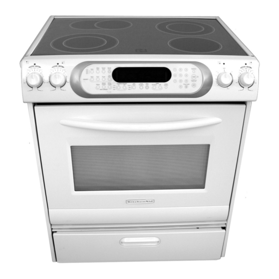
- Page 1 KAC-38 TECHNICAL EDUCATION SELF-CLEANING SLIDE-IN/FREESTANDING ELECTRIC RANGES Freestanding Model: KERA807P Slide-In Models: KESV808P, KESV908P, KESA907P, & KESI901P JOB AID 4317354...
- Page 2 FORWARD This KitchenAid Job Aid, “Self-Cleaning Slide-In/Freestanding Electric Ranges,” (Part #4317354), provides the technician with information on the installation, operation, and service of Self-Cleaning Slide-In/Freestanding Electric Ranges. It is to be used as a training Job Aid and Service Manual.
-
Page 3: Table Of Contents
Model & Serial Number Designations ................1-2 Model & Serial Number Label & Tech Sheet Locations ............. 1-3 Specifications ........................1-4 KitchenAid Electric Range Warranty .................. 1-6 INSTALLATION INFORMATION ................... 2-1 Installation Requirements ....................2-1 Tools And Parts ......................2-1 Location Requirements .................... - Page 4 Page COMPONENT TESTING ......................5-1 Infinite (Smart) Switch ......................5-1 Dual & Single Infinite & Warming Drawer Switches Models: KESV808, KESV908, & KESI901 ..............5-1 Control & Cooling Fan Thermal Switches ................5-2 Door Latch Assembly ......................5-2 Power Supply Transformer ....................5-3 Oven &...
-
Page 5: General
GENERAL SAFETY FIRST Your safety and the safety of others is very important. We have provided many important safety messages in this Job Aid and on the appliance. Always read and obey all safety messages. This is the safety alert symbol. This symbol alerts you to hazards that can kill or hurt you and others. -
Page 6: Model & Serial Number Designations
MODEL & SERIAL NUMBER DESIGNATIONS MODEL NUMBER MODEL NUMBER V 90 PRODUCT GROUP K = KITCHENAID PRODUCT IDENTIFICATION DR = DUAL FUEL RANGE DS = DUAL FUEL SLIDE-IN RANGE ER = ELECTRIC STANDARD RANGE ES = ELECTRIC SLIDE-IN RANGE GR = GAS STANDARD RANGE... -
Page 7: Model & Serial Number Label & Tech Sheet Locations
MODEL & SERIAL NUMBER LABEL & TECH SHEET LOCATIONS The Model/Serial Number label and Tech Sheet locations are shown below. Model/Serial Number Location (On Chassis Frame) Tech Sheet Location Warming Drawer Models Only (On Chassis Under Drawer) Model/Serial Number Location (On Chassis Frame) Tech Sheet Location Storage Drawer Models Only... -
Page 8: Specifications
SPECIFICATIONS... -
Page 10: Kitchenaid Electric Range Warranty
I. In Canada, travel or transportation expenses to customers who reside in remote areas. KITCHENAID OR KITCHENAID CANADA DO NOT ASSUME ANY RESPONSIBILITY FOR INCIDENTAL OR CONSEQUENTIAL DAMAGES. Some states or provinces do not allow the exclusion or limitation of incidental or consequential damages, so this exclusion or limitation may not apply to you. -
Page 11: Installation Information
INSTALLATION INFORMATION INSTALLATION REQUIREMENTS TOOLS AND PARTS Parts Supplied Assemble the required tools and parts before starting installation. Read and follow the safety instructions provided with any tools listed here. Tools Needed • Tape measure • Flat-blade screwdriver • Level •... -
Page 12: Location Requirements
LOCATION REQUIREMENTS Mobile Home - Additional Installation Re- quirements IMPORTANT: Observe all governing codes The installation of this range must conform to and ordinances. Failure to meet codes and the Manufactured Home Construction and ordinances could lead to fire or electrical shock. Safety Standard, Title 24 CFR, Part 3280 (for- •... -
Page 13: Product Dimensions
PRODUCT DIMENSIONS Freestanding Range 30" (76.2 cm) 7-7/8" (20 cm) 43-7/8" (111.4 cm) overall height 36" (91.4 cm) cooktop height with leveling legs lowered 1-1/2 turns 30" (76.2 cm) *27" (68.6 cm) to handle Slide-In Range 30-11/16" (77.9 cm) 35-5/8" (90.5 cm) 23-1/2"... -
Page 14: Installation Clearances
INSTALLATION CLEARANCES base cabinet depth and 36″ (91.4 cm) Cabinet opening dimensions shown are for ″ (64 cm) countertop depth, 24″ (61 cm) countertop height. Freestanding Range For minimum 13" (33 cm) max. clearance to upper cabinet depth the top of the cooktop, see 30"... -
Page 15: Electrical Requirements
ELECTRICAL REQUIREMENTS • The range can be connected directly to the If codes permit and a separate ground wire is fused disconnect (or circuit breaker box) used, it is recommended that a qualified elec- trical installer determine that the ground path through flexible, armored or nonmetallic sheathed, copper or aluminum cable. - Page 16 The cord should be Type SRD or SRDT with a If connecting to a 3-wire system: UL listed strain relief and be at least 4 ft. Local codes may permit the use of a UL listed, (1.22m) long. 3-wire, 250-volt, 40 amp range power supply cord (pigtail).
-
Page 17: Countertop Preparation (Slide-In Ranges Only)
COUNTERTOP PREPARATION Tile countertops may need the trim cut back 3/8″ (1.0 cm) from each front corner, and/or (SLIDE-IN RANGES ONLY) have the rounded edge flattened. The cooktop sides of the slide-in range fit over the cutout edge of the countertop. 30"... -
Page 18: Installation Instructions
INSTALLATION INSTRUCTIONS ELECTRICAL CONNECTION Direct Wire Power Supply Cord WARNING WARNING Electrical Shock Hazard Disconnect power before servicing. Electrical Shock Hazard Use 8 gauge copper or 6 gauge Disconnect power before servicing. aluminum wire. Use a new 40 amp power supply cord. Electrically ground range. - Page 19 Power Supply Cord Installation Connect the terminals (ring-type or spade with upturned ends) on the end of the WARNING: Improper connection of the equip- power cord to the power supply. ment-grounding conductor can result in a risk of electric shock. Check with a qualified electri- Complete electrical connection according cian or service technician if you are in doubt as to your type electrical supply (4-wire or...
- Page 20 Use a 1/4″ nut driver and remove the hex 3-wire connection: Power supply cord washer head screws from the terminal Use this method only if local codes permit blocks. connecting cabinet-ground conductor to neu- Connect the neutral (center) wire to the tral wire of power supply cord.
- Page 21 Direct Wire Installation: Copper or Alumi- Remove the ground-link screw from the num Wire range frame. Save the ground-link screw and cup washer. Bend the ground-link This range may be connected directly to the away from the range so that it does not fuse disconnect or circuit breaker box.
- Page 22 Insert the other 2 wires (lines 1 and 2) 3-wire connection: Direct wire under the other 2 screw clamps. Use this method only if local codes permit connecting ground conductor to neutral supply wire. Loosen (do not remove) the hex washer head screws and insert the neutral (white) wire under the screw clamp at the bottom of the center position terminal connector.
-
Page 23: Theory Of Operation
THEORY OF OPERATION CONVECTION BOWTIE BAFFLE AIRFLOW In a gas range, the convection fan will not turn on for the first four minutes of operation. This The bowtie baffle provides a wider air flow is to assure that a proper gas flame is present throughout the oven when using the convec- before the convection fan starts to circulate air tion cooking modes. - Page 24 — NOTES —...
-
Page 25: Component Access
COMPONENT ACCESS This section instructs you on how to service each component inside the Self-Cleaning Slide-In/ Freestanding Electric Ranges. The components and their locations are shown below. COMPONENT LOCATIONS Cooktop Components Power Supply Transformer Element & Limiter Hot Surface Control Power Indicators Supply Cooling Fan... -
Page 26: Removing The Eoc Assembly On Slide-In & Freestanding Models, And The User Interface
REMOVING THE EOC ASSEMBLY ON SLIDE-IN & FREESTANDING MODELS, AND THE USER INTERFACE c) Pull out on the bottom of the control WARNING panel, unclip the top edge from the bracket, and rotate the control panel forward so you can access the compo- nents. - Page 27 To remove the electronic oven control To remove the user interface: (EOC) assembly on freestanding models: a) Remove the electronic oven control a) Open the oven door, and remove the assembly (see steps 3 or 4). screws from the bottom of the control b) Remove the four machine screws from panel (see the photo in step 3b).
-
Page 28: Removing An Led Indicator And An Infinite Switch
REMOVING AN LED INDICATOR AND AN INFINITE SWITCH To remove an infinite switch: WARNING a) Pull the knob off the infinite switch you wish to service. b) Remove the two two screws from the infinite switch. Electrical Shock Hazard Disconnect power before servicing. Replace all parts and panels before operating. -
Page 29: Removing The Cooktop Glass
REMOVING THE COOKTOP GLASS Remove the cooktop glass brackets from WARNING the left and right sides of the range. Electrical Shock Hazard Side Bracket Screws Disconnect power before servicing. Lift the rear of the cooktop glass off the Replace all parts and panels before range, slide it out from under the front operating. -
Page 30: Removing The Control & Cooling Fan Thermal Switches And The Door Latch Assembly
REMOVING THE CONTROL & COOLING FAN THERMAL SWITCHES, AND THE DOOR LATCH ASSEMBLY To remove the door latch assembly: WARNING a) Open the oven door and remove the two front mounting screws from the air vent. Electrical Shock Hazard Disconnect power before servicing. Replace all parts and panels before Front Door Latch Screws operating. -
Page 31: Removing The Control Power Supply And The Power Supply Transformer
REMOVING THE CONTROL POWER SUPPLY AND THE POWER SUPPLY TRANSFORMER P2 P1 T3 WARNING Electrical Shock Hazard Disconnect power before servicing. Replace all parts and panels before operating. Failure to do so can result in death or electrical shock. Unplug range or disconnect power. Remove the control panel and rotate it To remove the power supply transformer: forward (see page 4-2, steps 2a through... -
Page 32: Removing An Element & Limiter And The Hot Surface Indicator Assembly
REMOVING AN ELEMENT & LIMITER AND THE HOT SURFACE INDICATOR ASSEMBLY c) Disconnect the wire from the limiter WARNING terminal. d) Remove the two limiter screws from the bottom of the element, and slide the limiter sensor out of the element. Limiter Screws Electrical Shock Hazard Disconnect power before servicing. -
Page 33: Removing The Rear Panel
REMOVING THE REAR PANEL Remove the three screws from the junc- WARNING tion box and position the box off the rear panel. Screw Electrical Shock Hazard Disconnect power before servicing. Replace all parts and panels before Junction Box operating. Failure to do so can result in death or electrical shock. -
Page 34: Removing An Oven Light Socket Assembly
REMOVING AN OVEN LIGHT SOCKET ASSEMBLY Unscrew the lens and bulb from the oven WARNING light socket assembly and remove them. Electrical Shock Hazard Disconnect power before servicing. Lens & Bulb Oven Light Socket Replace all parts and panels before Remove the rear panel from the unit (see operating. -
Page 35: Removing The Dual Broil Element
REMOVING THE DUAL BROIL ELEMENT Pull the dual broil element forward so that WARNING the wire connectors are inside the oven cavity. Disconnect the four wires from the inner and outer element terminals of the dual broil element. NOTE: When you discon- nect the wires, be careful not to allow them to pull back behind the access holes where Electrical Shock Hazard... -
Page 36: Removing The Oven Temperature Sensor
REMOVING THE OVEN TEMPERATURE SENSOR Remove the screws from the oven tem- WARNING perature sensor and remove the sensor. Electrical Shock Hazard Disconnect power before servicing. Replace all parts and panels before operating. Failure to do so can result in death or electrical shock. -
Page 37: Removing The Convection Element & Fan Motor
REMOVING THE CONVECTION ELEMENT & FAN MOTOR To remove the convection element: WARNING a) Remove the two screws from the ele- ment brackets. Element Screw Electrical Shock Hazard Disconnect power before servicing. Replace all parts and panels before operating. Failure to do so can result in death or electrical shock. - Page 38 To remove the convection fan motor: a) Remove the 7/16″ hex-nut from the convection fan and remove the fan from the motor shaft. NOTE: The nut has a left-hand thread so turn it clockwise to remove it. Convection Fan Motor Fan Nut e) Disconnect the two wires from the con- vection fan motor terminals.
-
Page 39: Removing The Cooling Fan
REMOVING THE COOLING FAN Use a 90° screwdriver, and remove the WARNING two screws from each end of the cooling fan cover, then remove the cover. Electrical Shock Hazard Disconnect power before servicing. Cooling Fan Cover Replace all parts and panels before operating. -
Page 40: Removing The Oven Tod
REMOVING THE OVEN TOD WARNING Wire Connector Screw (1 of 2) Wire Connector Electrical Shock Hazard Disconnect power before servicing. Replace all parts and panels before operating. Failure to do so can result in death or electrical shock. Unplug range or disconnect power. Pull the range out of its mounting location so that you can access the rear of the unit. -
Page 41: Removing The Hidden Bake Element
REMOVING THE HIDDEN BAKE ELEMENT Remove the four screws from the hidden WARNING bake element cover flanges. 4 Cover Flange Screws Electrical Shock Hazard Disconnect power before servicing. Replace all parts and panels before Bend the cover flanges down as far as operating. - Page 42 Carefully pull the hidden bake element and its mounting bracket out of the range. Pull Out Hidden Bake Element 4-18...
-
Page 43: Removing The Warming Drawer Temperature Sensor And Element
REMOVING THE WARMING DRAWER TEMPERATURE SENSOR AND ELEMENT WARNING Pull Lever Forward Right Electrical Shock Hazard Locking Disconnect power before servicing. Replace all parts and panels before operating. Right Drawer Hangers Failure to do so can result in death or electrical shock. - Page 44 To remove the warming drawer ele- b) Pull the element forward until the con- ment: nectors are inside the warming drawer area, and disconnect the wires from the a) Remove the two front and two rear element terminals. mounting screws from the element. Warming Drawer Element Wires Warming Drawer...
-
Page 45: Removing A Side Panel
REMOVING A SIDE PANEL WARNING Top Bracket Left Side Panel Top Screw Electrical Shock Hazard Disconnect power before servicing. Replace all parts and panels before operating. Failure to do so can result in death or electrical shock. Top Cutout Unplug range or disconnect power. Pull the range out of its mounting location Bottom Cutout so that you can access the rear of the unit. -
Page 46: Removing & Reinstalling The Oven Door
REMOVING & REINSTALLING THE OVEN DOOR Close the door to within six to eight inches, To remove the oven door: then pull out on the bottom of the door Fully open the door. while slowly closing the door, and remove Rotate the locking arm on the door hinge the hinge hangers from the slots in the from the locked “down”... -
Page 47: Removing The Oven Door Gasket
REMOVING THE OVEN DOOR GASKET Remove the oven door (see page 4-22 for Starting at one end of the door gasket, pull the procedure). the clips out of the liner holes, and remove the gasket. Remove the screw from the door gasket cover and remove the cover. -
Page 48: Removing The Decorative Glass And Oven Door Handle, The Hinges, And The Oven Door Glass
REMOVING THE DECORATIVE GLASS AND OVEN DOOR HANDLE, THE HINGES, AND THE OVEN DOOR GLASS Remove the oven door from the range e) Remove the two door handle screws (see page 4-22 for the procedure). from each of the brackets and remove the handle from the decorative glass. - Page 49 b) Position the door liner with the outer To remove the inner oven door glass: oven glass facing up, as shown. a) Remove the decorative glass and c) Remove the two screws from the lower handle from the door liner (see step 3). bracket for the outer oven glass.
- Page 50 — NOTES — 4-26...
-
Page 51: Component Testing
COMPONENT TESTING Before testing any of the components, perform • Check all connections before replacing com- the following checks: ponents, looking for broken or loose wires, failed terminals, or wires not pressed into • The most common cause for control failure is connectors far enough. -
Page 52: Control & Cooling Fan Thermal Switches
WARNING Electrical Shock Hazard Disconnect power before servicing. Replace all parts and panels before operating. Failure to do so can result in death or electrical shock. CONTROL & COOLING FAN DOOR LATCH ASSEMBLY THERMAL SWITCHES Motor Control Door Switch Opens @ 96°C (205°F) Closes @ 74°C (165°F) Cooling Fan Closes @ 70°C (158°F) -
Page 53: Power Supply Transformer
WARNING Electrical Shock Hazard Disconnect power before servicing. Replace all parts and panels before operating. Failure to do so can result in death or electrical shock. POWER SUPPLY TRANSFORMER OVEN & WARMING DRAWER TEMPERATURE SENSORS Primary Refer to page 4-12 for the procedure for servic- ing the oven temperature sensor, and page 4-19 for the warming drawer temperature sen- Refer to page 4-7 for the procedure for servic-... -
Page 54: Elements & Limiters
WARNING Electrical Shock Hazard Disconnect power before servicing. Replace all parts and panels before operating. Failure to do so can result in death or electrical shock. ELEMENTS & LIMITERS • OR-WH and BK (BU-WH and BK) = 52 to 64 Ω Refer to page 4-8 for the procedure for servic- LR (Dual Element) ing the elements &... -
Page 55: Dual Broil Element
WARNING Electrical Shock Hazard Disconnect power before servicing. Replace all parts and panels before operating. Failure to do so can result in death or electrical shock. DUAL BROIL ELEMENT CONVECTION ELEMENT Outer Element Inner Element Refer to page 4-11 for the procedure for servic- Refer to page 4-13 for the procedure for servic- ing the dual broil element. -
Page 56: Convection Fan Motor
WARNING Electrical Shock Hazard Disconnect power before servicing. Replace all parts and panels before operating. Failure to do so can result in death or electrical shock. CONVECTION FAN MOTOR COOLING FAN MOTOR Refer to page 4-15 for the procedure for servic- Refer to page 4-13 for the procedure for servic- ing the cooling fan. -
Page 57: Oven Tod
WARNING Electrical Shock Hazard Disconnect power before servicing. Replace all parts and panels before operating. Failure to do so can result in death or electrical shock. HIDDEN BAKE ELEMENT OVEN TOD Refer to page 4-17 for the procedure for servic- Refer to page 4-16 for the procedure for ser- ing the hidden bake element. -
Page 58: Warming Drawer Element
WARNING Electrical Shock Hazard Disconnect power before servicing. Replace all parts and panels before operating. Failure to do so can result in death or electrical shock. WARMING DRAWER ELEMENT Refer to page 4-19 for the procedure for servic- ing the warming drawer element. Unplug range or disconnect power. -
Page 59: Diagnostics & Troubleshooting
DIAGNOSTICS & TROUBLESHOOTING DIAGNOSTICS Door Relay Being Latch Meat Probe Switch Engaged Readout* Switch Code Code O . BROIL REL CYCLED AM34 UI30 EEKET - 002 #2 Oven Temp Warming Drawer #1 Oven Temp Version Sensor Readout* Sensor Readout* Sensor Readout * If available (3 dashes will be shown if not available) ENTERING MANUAL DIAGNOSTICS Within 120 seconds of power up, press the following keys to enable the relay capabilities listed... - Page 60 ERROR CODE Pressing the 3 key once will cycle to the next error code. An error code is displayed in the two right clock digits. ERROR CODE LIST ORDER ERROR CODE #1 MOST RECENT CODE ERROR CODE #2 ERROR CODE #2 ERROR CODE #3 ERROR CODE #3 ERROR CODE #4...
- Page 61 ERROR / FAILURE CODES Before proceeding with any corrective action, perform the following steps to enter the Diagnostic mode. 1. To recall last failure code, if not displayed, press the Cancel key to place the range in an idle state. 2.
- Page 62 FAILURE ERROR FAILURE ERROR MESSAGE/DESCRIPTION MESSAGE/DESCRIPTION (Leftmost (Rightmost (Leftmost (Rightmost 2 Clock 2 Clock 2 Clock 2 Clock SUGGESTED CORRECTIVE ACTION PROCEDURE SUGGESTED CORRECTIVE ACTION PROCEDURE Digits) Digits) Digits) Digits) MAIN SENSOR OPEN (top oven sensor opened) OVER TEMP COOK MAIN SENSOR SHORT or MAIN SENSOR SHORTED OVER TEMP CLEAN (top oven sensor shorted)
- Page 63 FAILURE ERROR FAILURE ERROR MESSAGE/DESCRIPTION MESSAGE/DESCRIPTION (Leftmost (Rightmost (Leftmost (Rightmost 2 Clock 2 Clock 2 Clock 2 Clock SUGGESTED CORRECTIVE ACTION PROCEDURE SUGGESTED CORRECTIVE ACTION PROCEDURE Digits) Digits) Digits) Digits) DOOR LATCH MSMATCH or DOOR LATCH MISMATCH LOST COMMUNICATION Systems (Door and latch switches do not agree.) PROCEDURE: Before proceeding, perform steps 1 through 3 above chart on page 6-3 NO OPERATING LATCH or LATCH NOT OPERATING...
-
Page 64: Troubleshooting
TROUBLESHOOTING HIDDEN EOC FUNCTIONS TEMPERATURE ADJUSTMENT The user activates all hidden EOC functions by 1. Press and hold the BAKE keypad for five (5) pressing and holding the appropriate key for 5 seconds. The current offset, if any, will be seconds. -
Page 65: Wiring Diagrams & Strip Circuits
WIRING DIAGRAMS & STRIP CIRCUITS WIRING DIAGRAMS TECH SHEET #9757662 KEYPAD MAIN OVEN SENSOR P3-1 POWER DISPLAY BOARD P3-2 BOARD MEAT PROBE P3-5 P3-6 WARM DRWR SENSOR P3-7 P3-8 DOOR SW P7-1 TRANSFORMER P7-2 THERMAL SW LATCH SW ° C ±3 °... - Page 66 TECH SHEET #9757663 KEYPAD MAIN OVEN SENSOR P3-1 POWER DISPLAY BOARD P3-2 BOARD DOOR SW P7-1 P7-2 LATCH SW P7-4 BAKE 2000 W K2 BAKE RELAY T3-2 TRANSFORMER OUTER BROIL 1450 W K3 OUTER BROIL RELAY T2-2 THERMAL SW OPENS @ INNER BROIL 1791 W K4 INNER BROIL RELAY T2-3...
-
Page 67: Strip Circuits
STRIP CIRCUITS CLEAN (Bake and inner and outer broil relays cycle) MAIN OVEN SENSOR P3-1 POWER BOARD P3-2 WARM DRWR SENSOR P3-7 P3-8 DOOR SW P7-1 P7-2 LATCH SW (FOR CLEAN ONLY) P7-4 BAKE 2000 W K2 BAKE RELAY T3-2 T3-1 OUTER BROIL 1450 W T2-2... - Page 68 WARMING DRAWER WARM DRWR SENSOR P3-7 POWER BOARD P3-8 WARM DRWR 850 W K6 WARM DRWR RELAY T2-4 OR/W T2-1 CONTROL POWER/CLOCK P5-3 DISPLAY POWER BOARD BOARD P4-1 P5-1 TRANSFORMER THERMAL SW OPENS @ 96.1°C ±3°C TOD 130°C (266°F) (205°F ±5.4°F) CONSOLE/OVEN LIGHTS OVEN LIGHT 40 W...
- Page 69 CONVECTION ROAST MAIN OVEN SENSOR P3-1 POWER P3-2 BOARD BAKE 2000 W T3-1 K2 BAKE RELAY T3-2 CONVECTIONFAN 60 W K9 CONVECTIONFAN RELAY P4-1 P4-4 OUTER BROIL 1450 W K3 OUTER BROIL RELAY T2-1 T2-2 K1A DLB RELAY 1 T1A-2 T1A-1 K1B DLB RELAY 2 T1B-2...
- Page 70 SURFACE ELEMENT (SINGLE) LED CONSOLELIGHT BR/W ELEMENT 1800 W FROM P4-6 POWER BOARD SMART KNOB SWITCH COOKTOP ELEMENT SURFACE INDICATOR LIGHT COOLING FAN POWER BOARD P4-1 P4-5 COOLINGFAN 60 W K10 COOLINGFAN RELAY THERMAL SW CLOSES @ 70 ° C ±3 ° C (158 °...
- Page 71 TECH SHEET #9757663 ONLY SURFACE ELEMENT (DUAL) SURFACE ELEMENT (SINGLE) TYPICAL SURFACE ELEMENT (ACCUSIMMER) SURFACE ELEMENT (WARM)
- Page 72 — NOTES —...
- Page 73 — NOTES —...
- Page 74 — NOTES — 7-10...
- Page 75 WARRANTY INFORMATION SOURCES IN THE UNITED STATES: FOR PRODUCT SPECIFICATIONS AND WARRANTY INFORMATION CALL: FOR WHIRLPOOL PRODUCTS: 1-800-253-1301 FOR KITCHENAID PRODUCTS: 1-800-422-1230 FOR ROPER PRODUCTS: 1-800-447-6737 FOR TECHNICAL ASSISTANCE WHILE AT THE CUSTOMER’S HOME CALL: THE TECHNICAL ASSISTANCE LINE: 1-800-253-2870...