Table of Contents
Advertisement
USER GUIDE AND SPECIFICATIONS
NI USB-6509
Contents
This document contains information about using the National Instruments
USB-6509 data acquisition (DAQ) device with NI-DAQmx 8.7 and later.
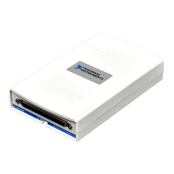
The NI USB-6509 is a bus-powered 96-channel, digital input/output (I/O)
device. The NI USB-6509 features 96 TTL/CMOS-compatible digital I/O
lines, a watchdog timer, digital input filtering and change detection, and
output programmable power-up states. The NI USB-6509 also features an
optional external DC power supply that can increase the I/O drive strength.
Getting Started ........................................................................................ 2
Installing Software ........................................................................... 2
Installing the Hardware.................................................................... 3
USB Cable Strain Relief .................................................................. 3
Mounting the NI USB-6509 ............................................................ 3
Desktop Use.............................................................................. 3
DIN Rail Mounting................................................................... 4
Panel Mounting......................................................................... 5
Hardware Overview ................................................................................ 6
Programming Devices in Software ......................................................... 7
Related Documentation.................................................................... 8
I/O Connector.......................................................................................... 8
Pin Assignments .............................................................................. 8
SH100-100-F Pin Assignments ................................................ 8
R1005050 Pin Assignments...................................................... 10
Signal Descriptions .......................................................................... 11
Digital I/O ............................................................................................... 12
Static DIO on NI USB-6509 Devices .............................................. 12
Digital I/O Circuitry......................................................................... 12
I/O Protection................................................................................... 12
I/O State at Power-On/Power-Off/Suspend ..................................... 13
I/O Pull-Up/Pull-Down Resistor...................................................... 13
High DIO State ......................................................................... 13
Low DIO State.......................................................................... 14
Increasing Current Drive on NI USB-6509 Devices ....................... 15
Advertisement
Table of Contents

Related Manuals for NI USB-6509


Summary of Contents for NI USB-6509
-
Page 1: Table Of Contents
NI USB-6509 This document contains information about using the National Instruments USB-6509 data acquisition (DAQ) device with NI-DAQmx 8.7 and later. The NI USB-6509 is a bus-powered 96-channel, digital input/output (I/O) device. The NI USB-6509 features 96 TTL/CMOS-compatible digital I/O lines, a watchdog timer, digital input filtering and change detection, and output programmable power-up states. -
Page 2: Getting Started
Getting Started NI USB-6509 devices feature up to 96 bidirectional per-port static DIO lines. If you have not already installed your device, refer to the NI-DAQmx for USB Devices Getting Started Guide. Before installing your DAQ device, you must install the software you plan to use with the device. -
Page 3: Installing The Hardware
3 USB Cable Figure 1. USB Cable Strain Relief Options Mounting the NI USB-6509 You can use the NI USB-6509 on a desktop or mount it to a standard DIN rail or a panel. Desktop Use You can use the NI USB-6509 on a desktop. The NI USB-6509 has grooves on the underside that allow it to be stacked on top of other NI USB-6509 devices. -
Page 4: Din Rail Mounting
Figure 2. Note Do not apply the rubber feet if you are panel mounting the NI USB-6509 or stacking multiple NI USB-6509 devices. Figure 2. Applying Rubber Feet to the NI USB-6509... -
Page 5: Panel Mounting
Figure 3. Figure 3. Mounting the NI USB-6509 on a Panel Notes Do not apply the rubber feet to the NI USB-6509 when panel mounting the device. Apply strain relief, as described in the USB Cable Strain Relief section, before panel mounting the NI USB-6509. -
Page 6: Hardware Overview
Hardware Overview Figure 4 shows the key functional components of the NI USB-6509. +5 V Fuse and Filter 24 mA DIO Tranceivers 12 VDC Input External Power Port 0 12 V to 5 V Regulation Port 1 Port 2 Port 3... -
Page 7: Programming Devices In Software
Programming Devices in Software National Instruments measurement devices for USB are packaged with NI-DAQ driver software, an extensive library of functions and VIs you can call from your application software, such as LabVIEW or ™ ™ LabWindows /CVI , to program all the features of your NI measurement devices. -
Page 8: Related Documentation
R1005050 ribbon cable with the CB-50 or CB-50LP connector block. Do not make connections to the digital I/O that exceed the maximum I/O Caution specifications. Doing so may permanently damage the NI USB-6509 device and the computer. Refer to the Signal Descriptions Specifications sections for information about maximum input ratings. - Page 9 P0.0 P6.0 P3.0 P9.0 +5 V +5 V Figure 6. Pin Assignments for the NI USB-6509 using the SH100-100-F Refer to the Signal Descriptions section for information about the signals available on this connector. © National Instruments Corporation NI 6509 User Guide and Specifications...
-
Page 10: R1005050 Pin Assignments
R1005050 Pin Assignments Figure 6 shows the pin assignments for the NI USB-6509 using the R1005050 cable. The naming convention for each pin is PX.Y, where X is the port (P) number, and Y is the line number or name. -
Page 11: Signal Descriptions
Signal Descriptions Table 1 lists the signals and descriptions for all signals available on the NI USB-6509 device. Table 1. NI USB-6509 Signal Descriptions Signal Name Description 1, 3, 5, 7, 9, 11, 13, 15 P2.<7..0> Bi-directional data lines for P2.7... -
Page 12: Digital I/O
Digital I/O Static DIO on NI USB-6509 Devices You can use each of the NI USB-6509 DIO lines as a static digital input (DI) or digital output (DO) line. You can use static DIO lines to monitor or control digital signals. Each DIO port can be configured as a DI or DO port. -
Page 13: I/O State At Power-On/Power-Off/Suspend
I/O Pull-Up/Pull-Down Resistor The NI USB-6509 facilitates user-configurable pull-up or pull-down tasks. Each DIO channel is connected to a 100 kΩ resistor and can be pulled high or low using the back-panel switch, shown in Figure 5. Using this switch pulls all 96 DIO lines high when set to HIGH or low when set to LOW. -
Page 14: Low Dio State
100 kΩ resistor. If you want to pull a specific line high, connect a pull-up resistor that gives you a minimum of 2 V. Use the largest possible resistance value so that you do not use more current than necessary to perform the pull-up task. NI 6509 User Guide and Specifications ni.com... -
Page 15: Increasing Current Drive On Ni Usb-6509 Devices
Based on the USB specification, the maximum current that a bus-powered USB device can draw is limited to 500 mA. Consequently, when the NI USB-6509 is powered only from a USB port, the current drive capacity at output channels is limited. -
Page 16: Dio Signal Connection
The inputs/outputs are disabled • The LED on the back panel is blinking If you want to increase the current drive capacity on the NI USB-6509, you can use an optional external +12 VDC power supply. For more information, refer to the Optional +12 VDC Power Supply Installation section. -
Page 17: Protecting Inductive Loads
24 mA, driving a relay greater than 24 mA, and driving solid-state relays. Driving a Relay <24 mA Figures 13 and 14 show examples of connecting the NI USB-6509 to a relay that does not require more than 24 mA of current. -
Page 18: Driving A Relay >24 Ma
Figure 14. NI USB-6509 Sourcing Connection Example, <24 mA Driving a Relay >24 mA Figures 15 and 16 are examples of connecting the NI USB-6509 to a relay that requires more than 24 mA of current. These examples use an additional transistor circuit. -
Page 19: Driving Ssrs
Device error—USB power budget possibly exceeded Power Connection Optional +12 VDC Power Supply Installation To install a +12 VDC power supply into the NI USB-6509, complete the following steps: Ensure that the device is powered off by unplugging the USB cable from the device. -
Page 20: +5 V Power Available At I/O Connector
The I/O connector power has a fuse for overcurrent protection. This fuse is not customer replaceable. If the fuse is blown, return the device to NI for repair. The power pins, +5V and GND, connect to the computer power supply and are Caution not isolated. -
Page 21: Digital Filtering Example
Figure 18 shows a rising (0 to 1) transition. The same filtering applies to falling (1 to 0) transitions. © National Instruments Corporation NI 6509 User Guide and Specifications... -
Page 22: Programmable Power-Up States
Programmable Power-Up States At power-up, the output drives on the NI USB-6509 are disabled. All lines are user-configurable for high-impedance input, high output, or low output. User-configurable power-up states are useful for ensuring that the NI USB-6509 powers up in a known state. -
Page 23: Change Detection Example
If the switch closure is noisy, enable digital filtering for this line. In this example, the NI USB-6509 reports rising edges only on bit 1, falling edges only on bit 0, and rising and falling edges on bits 7, 6, 5, and 4. -
Page 24: Cables And Accessories
– 1) × 20.83 ns (approximately watchdog timer is configurable up to (2 1.5 minutes) before it expires. Cables and Accessories Table 5 lists the products available for use with the NI USB-6509. Table 5. NI USB-6509 Connectivity Options Cable Accessory SH100-100-F shielded cable—part number 185095-01 (1 m) - Page 25 Output high voltage (V 4.3 V 5.0 V — at –2 mA — 4.9 V — at –12 mA — 4.5 V — at –24 mA 2.8 V 4.0 V — © National Instruments Corporation NI 6509 User Guide and Specifications...
- Page 26 (7.0 × 4.1 × 1.3 in.) I/O connector ..........100-pin female 0.050 series SCSI Weight ............Approx. 239 g (8.4 oz) If you are using the NI USB-6509 in full-speed mode, device performance is lower. NI 6509 User Guide and Specifications ni.com...
- Page 27 , search by model number or product line, and click the appropriate link certification in the Certification column. Hazardous Locations The NI USB-6509 is not certified for use in hazardous locations. Environmental The NI USB-6509 device is intended for indoor use only. Operating temperature (IEC 60068-2-1 and IEC 60068-2-2) ..
- Page 28 Certification column. Environmental Management NI is committed to designing and manufacturing products in an environmentally responsible manner. NI recognizes that eliminating certain hazardous substances from our products is beneficial not only to the environment but also to NI customers.
-
Page 29: Safety Guidelines
The following section contains important safety information that you must follow when installing and using the NI USB-6509. Do not operate the NI USB-6509 in a manner not specified in this document. Misuse of the device can result in a hazard. You can compromise the safety protection built into the device if the device is damaged in any way. - Page 30 Working Voltage is the highest rms value of an AC or DC voltage that can occur across any particular insulation. MAINS is defined as a hazardous live electrical supply system that powers equipment. Suitably rated measuring circuits may be connected to the MAINS for measuring purposes. NI 6509 User Guide and Specifications ni.com...
-
Page 31: Where To Go For Support
Turkey 90 212 279 3031, United Kingdom 44 (0) 1635 523545 National Instruments, NI, ni.com, and LabVIEW are trademarks of National Instruments Corporation. Refer to the Terms of Use section on ni.com/legal for more information about National Instruments trademarks. Other product and company names mentioned herein are trademarks or trade names of their respective companies.
Need help?
Do you have a question about the USB-6509 and is the answer not in the manual?
Questions and answers