Table of Contents
Advertisement
Installation instructions
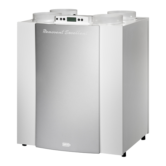
Heat recovery appliance
Renovent Excellent 300/400 (Plus)
STORE NEAR THE APPLIANCE
Use of this appliance is not permitted for persons, including children, with limited intellectual abilities, serious physical limitations or
lack of experience and knowledge, unless they are supervised by, or have received instructions of how to use the appliance from,
a person who is responsible for their safety.
Children must be supervised to ensure that they do not play with the appliance.
Advertisement
Table of Contents

Related Manuals for Brink Renovent Excellent 300


Summary of Contents for Brink Renovent Excellent 300
- Page 1 Installation instructions Heat recovery appliance Renovent Excellent 300/400 (Plus) STORE NEAR THE APPLIANCE Use of this appliance is not permitted for persons, including children, with limited intellectual abilities, serious physical limitations or lack of experience and knowledge, unless they are supervised by, or have received instructions of how to use the appliance from, a person who is responsible for their safety.
-
Page 2: Table Of Contents
Table of contents Delivery............Maintenance ..........Scope of delivery ..........Filter cleaning ..........Accessories Renovent Excellent ....Maintenance ..........Application ............ Electric diagrams........10.1 Basic diagram ..........Version............10.2 Wiring diagram ..........Technical information ........Fan graphs ............. Electric connections accessories ..... Exploded view appliance ........ -
Page 3: Delivery 1
Delivery Chapter 1 1.1 Scope of delivery Before starting installation of the heat recovery unit, check that it has been supplied complete and undamaged. The scope of delivery of the heat recovery unit Renovent Excellent includes the following components: Heat recovery appliance type Renovent Excellent Wall mounting bracket kit containing: "... -
Page 4: Delivery
Chapter 1 Delivery 1.2 Accessories Renovent Excellent Article description Article code Synthetic duct Ø150 mm / Length 2250 mm (box of 4) 200121 Synthetic duct Ø180 mm / Length 2250 mm (box of 4) 200131 Synthetic bend 90° Ø150 mm (box of 8) 200122 Synthetic bend 90°... - Page 5 Delivery Chapter 1 Article Article description code Splitter RJ12 510472 sensor surface-mounted 511396 Transmitter wireless remote control 2 positions (with. battery) 531785 Transmitter wireless remote control 4 positions (with. battery) 531786 Receiver wireless remote control (for battery version) 531787 Kit wireless remote control 2 positions (1 transmitter & 1 receiver) 531788 Kit wireless remote control 4 positions (1 transmitter &...
- Page 6 Chapter 1 Delivery Article Article description code Hknvgt"mkv"3"z"H9"Ýnvgt"*3"reu+ 531771 Filter kit 1x G3 & 1x F7 (1 pcs/ 1 pcs) 531773 RH-sensor 310657 Renovent Excellent...
-
Page 7: Application
Application Chapter 2 The Brink Renovent Excellent is a ventilation unit with heat re- These installation instruction describe both the standard Reno- eqxgt{"ykvj"cp"ghÝekgpe{"qh";7'."c"oczkowo"xgpvkncvkqp"ecrc- vent Excellent and the Renovent Excellent Plus. city of 300 or 400 m /h and low-energy fans. Features Reno- The Renovent Excellent (Plus) is available in the left-handed qt"... -
Page 8: Version
Chapter 3 Version 3.1 Technical information Renovent Excellent 300 Supply voltage [V/Hz] 230/50 Protection degree IP30 Dimensions (w x h x d) [mm] 675 x 765 x 564 Duct diameter [mm] Ø150/ Ø160 External diameter condensate discharge [mm] Ø32 Weight [kg]... - Page 9 Version Chapter 3 Renovent Excellent 400 Supply voltage [V/Hz] 230/50 Protection degree IP30 Dimensions (w x h x d) [mm] 675 x 765 x 564 Duct diameter [mm] Ø180 External diameter condensate discharge [mm] Ø32 Weight [kg] Filter class G3 (F7 optional for supply) Fan setting (factory setting) Ventilation capacity [m Permissible resistance ducts system [Pa]...
-
Page 10: Fan Graphs
3.2 Fan graphs Note: The value stated in the circle is the capacity per fan (in Watt) Flow rate [m Fan graph Renovent Excellent 300 Note: The value stated in the circle is the capacity per fan (in Watt) Flow rate [m... -
Page 11: Exploded View Appliance
Version Chapter 3 3.3 Exploded view appliance Rear view display cover 1 Service connector Computer connection for service purposes. 2 Display and 4 control buttons Interface between user and control electronics. 3 Control board Contains the control electronics for the basic functions. 4 Gzvtcev"ckt"Ýnvgt Hknvgtu"ckt"Þqy"htqo"fygnnkpi 5 Preheater... -
Page 12: Connections And Dimensions
Chapter 3 Version 3.4 Connections and dimensions Renovent Excellent 300/400 3.4.1 Renovent Excellent right-handed version Renovent Excellent Right-handed 2/2 Renovent Excellent Right-handed 4/0 1 = To dwelling 2 = To atmosphere 3 = From dwelling 4 = From atmosphere 5 = Electric connections... -
Page 13: Renovent Excellent Left-Handed Version
Version Chapter 3 3.4.2 Renovent Excellent left-handed version Renovent Excellent left-handed 2/2 Renovent Excellent left-handed 4/0 10 mm Mounting wall suspension kit Renovent Excellent left-handed 3/1 Renovent Excellent... -
Page 14: Operation
Chapter 4 Operation 4.1 Description Vjg"eqpvtqn"u{uvgo"jcu"vjtgg"xgpvkncvkqp"oqfgu0"Vjg"ckt"Þqy" The appliance comes plug and play and operates fully auto- matically. The extracted indoor air heats up the fresh, clean rate can be adjusted per ventilation mode. The constant vo- nwog"eqpvtqn"u{uvgo"gpuwtgu"vjcv"vjg"ckt"Þqy"tcvg"qh"vjg"uwrrn{" outdoor air. That saves energy and fresh air is sent to the re- quired rooms. -
Page 15: Installation
If Brink synthetic (EPE) pipe is used Preferably use Brink incorporated ducts. These ducts have here, additional insulation is not necessary. - Page 16 ̋" Ejqqug"vjg"nqecvkqp"qh"vjg"uwrrn{"xcnxgu"vq"rtgxgpv"hqwnkpi" the tiles. and draught. We recommend to use the Brink supply val- ves. A = Spacing 10 mm above roof deck B = Roof insulation...
-
Page 17: Electric Connections
Installation Chapter 5 5.5 Electric connections 5.5.1 Connecting the power plug The appliance can be connected to an easily accessible, Warning earthed wall socket with the plug that is mounted to the ap- The fans and control board carry a high volta- pliance. -
Page 18: Display
Chapter 6 Display image 6.1 General explanation control panel Chvgt"qrgtcvkpi"vjg"mg{"ÒOgpwÓ."vjg"mg{u"Ð-Ñ"qt"Ð/Ñ""ecp"dg"wugf" The LCD display shows what the operating situation of the ap- pliance is. Four control keys can be used to call up and modify to select from three different menus, including: settings in the control unit program. -
Page 19: Operating Mode
Display Chapter 6 6.2 Operating mode In operating mode the display may simultaneously show 4 dif- ferent situations/values. = Status fan situation, image coupled appliances (see § 6.2.1) 4" ?" Ckt"Þqy"tcvg (see § 6.2.2) = Message text"g0i0"vgzv"Ýnvgt"ukvwcvkqp."cevkxcvkqp"gzvgt- nal switch contact etc. (see § 6.2.3) = Fault symbol (see §... -
Page 20: Message Text For Operating Mode
Chapter 6 Display 6.2.3 Message text for operating mode This part of the display may show a message text. The oguucig" vgzv" ÐHknvgtÑ" cnyc{u" vcmgu" rtgegfgpeg" qxgt" vjg" other message texts. The following message text may appear during operating mode. Message text Description on display... -
Page 21: Settings Menu
Warning: Because changes may affect the proper performance of the appliance, changes of settings not described here require consultation with Brink. Incorrect settings may seriously affect the proper perfor- mance of the appliance! Use keys ‘-‘ and ‘+’ key to modify selected set value. -
Page 22: Readout Menu
Chapter 6 Display 6.4 Readout menu The readout menu can be used to call up a number of 3. Activate the readout menu. current sensor values to obtain more information on the appliance's performance. Modifying values of set- tings is not possible in the readout menu. The readout menu can be displayed as follows. -
Page 23: Service Menu
Display Chapter 6 6.5 Service menu The service menu shows the most recent 10 fault messages. Use the ‘+’ and the ‘-’ key to scroll through the messages in the service menu. In the event of a locking fault, the settings menu and the readout menu are blocked and only the service menu can be opened;... -
Page 24: Rwvvkpi"Kpvq"Qrgtcvkqp
Chapter 7 Putting into operation 7.1 Switching the appliance on and off There are two methods to switch the appliance on or off. - Switching on and off by inserting or pulling the power plug. - Switching on and off through software on the appliance display. Switching off: Switching on ̋"... -
Page 25: Setting The Air Quantity
Putting into operation Chapter 7 904"Ugvvkpi"vjg"ckt"Þqy"tcvg Ugg"vjg"ugvvkpiu"ogpw."¸805."hqt"ejcpikpi"vjg"Þqy"tcvgu0 The factory supplies the Renovent Excellent for the Renovent Gzegnngpv"522"Þqy"tcvgu"ugv"vq"72."322."372"gp"447"o /h and for the Renovent Excellent 400 set to 50, 100, 200 and 300 /h respectively. The performance and the energy consump- tion of the Renovent Excellent depend on the pressure drop in vjg"fwev"u{uvgo"cu"ygnn"cu"qp"vjg"Ýnvgt"tgukuvcpeg0 Important: Mode :... -
Page 26: Fault
E999 still appears, then replace the control board by a board of the correct type. Renovent Excellent 300 Renovent Excellent 400 Renovent Excellent 300 Plus Renovent Excellent 400 Plus 8.2 Display codes Non-locking fault When the appliance detects a non-locking fault, it will still keep running (limitedly). - Page 27 Fault Chapter 8 Fault Cause Action appliance Action installer code E100 ̋ Take the voltage from the appliance. Pressure sensor supply fan - Switches to constant rpm control. ̋ Check the red pressure hoses (and defective. - The preheater switches on at outdoor Red pressure hoses blocked pressure tubes) for fouling, kinking (non-locking...
-
Page 28: Maintenance
Chapter 9 Maintenance 9.1 Filter cleaning 6" Rnceg" vjg" Ýnvgtu" dcem" vjg" ucog" yc{" cu" vjg{" ygtg" vcmgp" User maintenance is limited to periodically cleaning or repla- ekpi"vjg"Ýnvgtu0"Vjg"Ýnvgt"qpn{"jcu"vq"dg"engcpgf"yjgp"vjcv"ku" out. indicated on the display (it shows the text "FILTERÑ+" qt." kh" c" ownvkrng"uykvej"ykvj"Ýnvgt"kpfkecvkqp"ku"oqwpvgf."yjgp"vjg"tgf"... -
Page 29: Maintenance
Maintenance Chapter 9 9.2 Maintenance Remove the heat exchanger. Be careful not to damage the Installer maintenance includes cleaning the heat exchanger foam parts in the appliance. and fans. Dependent on the conditions, this must done about once every three years. Switch off the appliance on the control panel (Press the ‘-’... - Page 30 Chapter 9 Maintenance Remove 4 pressure hoses and 3 connectors from the 11 Clean the fans with a soft brush. board. Make sure the balancing weights do not shift! Slide the fan assembly out of the appliance. 12 Replace the separated part of the fan assembly and recon- nect the loose pressure hoses to the pressure tubes.
-
Page 31: Electric Diagrams
Electric diagrams Chapter 10 10.1 Basic diagram 2"("32"Xs 230VAC 50Hz 24V/ 4,5 VA 2"/"32"Xq A = Multiple switch N = Not applicable B = Preheater O = E bus connector (polarity sensitive) or OpenTherm, C = Outdoor temperature sensor application depending on parameter setting 8 D = Control board P = Postheater (Plus version) E = Supply fan... -
Page 32: Wiring Diagram
Chapter 10 Electric diagrams 10.2 Wiring diagram = brown = blue = green/yellow = white = wire no.1 = wire no.2 C10 = yellow C11 = green Excellent Excellent Excellent Excellent 400 Plus 300 Plus A = Connection for multiple switch G = Control panel B = Preheater H = Indoor temperature sensor... -
Page 33: Electric Connections Accessories
Electric connections accessories Chapter 11 11.1 Connections connectors Connector X1 eBus or. OpenTherm connector X1 Two-pole screw connector. Set ex factory as eBus connector; after modifying parameter 8 in the Settings menu, also suitable as OpenTherm connector (see §11.3). Only suitable for low voltage Note: Hqt"vjg"gDwu"Crrnkecvkqp."vjku"eqppgevqt"ku"rqnctkv{/urgekÝe0 Not suitable for 230V! -
Page 34: Connection Examples Multiple Switch
Chapter 11 Electric connections accessories 11.2 Connection examples multiple switch A multiple switch can be connected to the modular connector X2 of the Renovent Excellent. This modular connector X2 is directly accessible at the rear of the display cover (see §11.1) without having to take it off. 330403"Ownvkrng"uykvej"ykvj"Ýnvgt"kpfkecvkqp 230 V 50 Hz... -
Page 35: Coupling Through Ebus; All Appliances Equal Ckt"Þqy"Tcvg
Electric connections accessories Chapter 11 11.3 Couple through eBus contact; cnn"crrnkcpegu"gswcn"ckt"Þqy"tcvg Important: Because of polarity sensitivity, always connect contacts X1-1 to X1-1 and contacts X1-2 to X1-2. Never connect X1-1 and X1-2. A maximum of 10 appliances (1 Master + 9 Slave max.) 230V 230V 230V... -
Page 36: Wiring Diagram Postheater Connection (Only For Renovent Excellent Plus)
Chapter 11 Electric connections accessories 3307"Yktkpi"fkcitco"rquvjgcvgt"eqppgevkqp"*qpn{"rquukdng"hqt"Tgpqxgpv"Gzegnngpv"Rnwu+ The electrical connections of the postheater and the extra preheater are the same; the only difference is that the postheater has an ad- ditional temperature sensor that must be wired to connector X15. Please refer to the mounting instructions that came with the heater for more extensive information regarding installation of the postheater or the extra preheater. - Page 37 Electric connections accessories Chapter 11 3307"Eqppgevkqp"gzcorng"igq"jgcv"gzejcpigt"*qpn{"rquukdng"hqt"vjg"Tgpqxgpv"Gzegnngpv"Rnwu+ 腭 A geo heat exchanger can be connected to the Re- 30°C novent Excellent Plus. 臊 A geo heat exchanger can be connected to connec- tion no. 5 (GND) and no. 9 (+) of 9-pole connector X15;...
-
Page 38: Connecting External Switch Contact (Only Possible For Renovent Excellent Plus)
Chapter 11 Electric connections accessories 3309"Eqppgevkpi"gzvgtpcn"uykvej"eqpvcev"*qpn{"rquukdng"hqt"Tgpqxgpv"Gzegnngpv"Rnwu+ An external switch contact (e.g. switch or relay contact) can be connected to the Renovent Excellent Plus. This external switch contact can be connected to connections no. 1 and no. 2 of 9-pole connector X15; this 9-pole connector is directly accessible at the rear of the top without having to dismount the display cover (see also §11.1). -
Page 39: Renovent Excellent Plus)
Electric connections accessories Chapter 11 330:"Eqppgevkqp"vq"2/32"X"kprwv"*qpn{"rquukdng"hqt""Tgpqxgpv"Gzegnngpv"Rnwu+ The Renovent Excellent Plus can be equipped with an external provision with 0-10 volt control) (e.g. humidity sensor or CO sensor). This external provision can be connected to pins no. 3 and no. 4 of 9-pole connector X15; this 9-pole connector is directly accessible at the rear of the top without having to dismount the display cover (see also §11.1). -
Page 40: Service
Chapter 12 Service 12.1 Exploded view When ordering parts, in addition to the article code number Example (see exploded view), please state the type of the heat recovery Appliance type : Renovent Excellent 4/0 R appliance, the serial number, the year of production and the name of the part: Serial number : 420020113201... -
Page 41: Service Articles
Cable with power plug 230 volt with display cover* 531782 Filter door left 531934 Filter door right 531935 The mains cable has a print connector. When replacing it, always order a replacement mains cable Brink Vq"cxqkf"fcpigtqwu"ukvwcvkqpu."c"fcocigf"ockpu"ujqwnf"qpn{"dg"tgrncegf"d{"c"swcnkÝgf"rgtuqp# OqfkÝecvkqpu"tgugtxgf Dtkpm"Enkocvg"U{uvgou"D0"X0"eqpvkpwqwun{"uvtkxgu"chvgt"kortqxgogpv"qh"rtqfwevu"cpf"tgugtxgu"vjg"tkijv"vq"ejcpig"vjg"urgekÝecvkqpu without prior notice. Renovent Excellent... -
Page 42: Setting Values
Chapter 13 Setting values UVGR" FKURNC["VGZV"- HCEVQT[ FGUETKRVKQP UVGR ADJUSTING RANGE U[ODQNU SETTING 01 Ckt"Þqy"tcvg"oqfg"Gze0"522"<"oqfg" 50 m /h or 50 m Ckt"Þqy"tcvg"oqfg"Gze0"622"<"oqfg" 50 m /h or 50 m 02 Ckt"Þqy"tcvg"oqfg"Gze0"522"<"oqfg"3 100 m 50 m /h - 300 m Ckt"Þqy"tcvg"oqfgv"Gze0"622"<"oqfg"3 100 m 50 m /h - 400 m 03 Ckt"Þqy"tcvg"oqfg"Gze0"522"<"oqfg"4... - Page 43 Setting values Chapter 13 UVGR" HCEVQT["UGVVKPIU" FKURNC["VGZV"- FGUETKRVKQP UVGR ADJUSTING RANGE TGP0"GZE0"RNWU U[ODQNU 0 (= Extract fan off) 1 *?"Cduqnwvg"okp0"Þqy"tcvg"72o 2 (= Flow rate mode 1) Extract fan mode 3 (= Flow rate mode 2) 4 (= Flow rate mode 3) switching input 1 5 (= Multiple switch) 6 *?"Oczkowo"Þqy"tcvg+...
-
Page 44: Declaration Of Conformity
DECLARATION OF CONFORMITY Manufacturers : Brink Climate Systems B.V. Address: R.D. Bügelstraat 3 7951 DA Staphorst, The Netherlands Product: Heat recovery unit type: Renovent Excellent 300/400 " " " " " Tgpqxgpv"Gzegnngpv"5221622"Rnwu The product described above complies with the following directives:...
Need help?
Do you have a question about the Renovent Excellent 300 and is the answer not in the manual?
Questions and answers