Advertisement
Table of Contents
Advertisement
Table of Contents

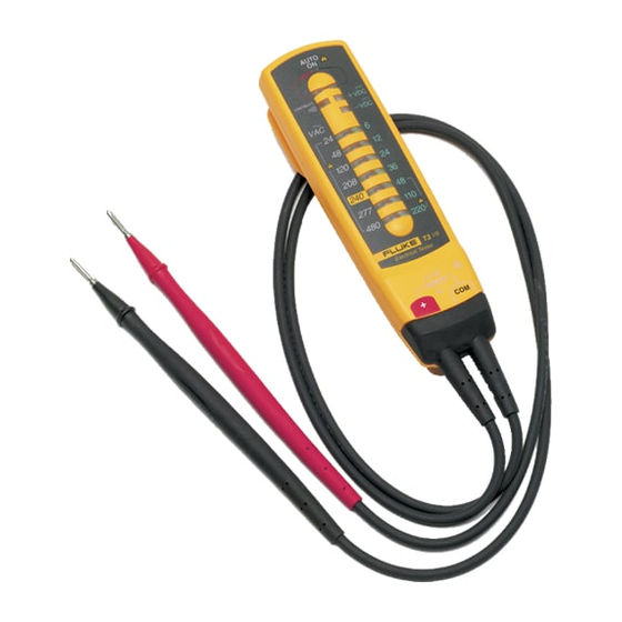
Summary of Contents for Fluke T3
- Page 1 ® Tester Calibration Manual PN 1599206 February 2001 © 2001 Fluke Corporation, All rights reserved. Printed in USA All product names are trademarks of their respective companies.
- Page 2 Fluke authorized resellers shall extend this warranty on new and unused products to end-user customers only but have no authority to extend a greater or different warranty on behalf of Fluke. Warranty support is available only if product is purchased through a Fluke authorized sales outlet or Buyer has paid the applicable international price.
-
Page 3: Table Of Contents
Table of Contents Title Page Introduction......................1 Definition Symbols Used in this Manual............1 Safety Information ..................... 2 Parts and Service....................3 Specifications..................... 3 Cleaning the Tester .................... 4 Required Equipment ..................4 Performance Tests....................4 Testing the Voltage Function ................ 4 Continuity Function Tests ................ - Page 4 Calibration Manual...
- Page 5 List of Tables Table Title Page Symbols........................1 DC and AC Voltage Tests..................4 Replacement Parts and Accessories ............... 8 List of Figures Figure Title Page Calibration Adjustment Point................. 6 Replacing the Batteries................... 7...
- Page 6 Calibration Manual...
-
Page 7: Introduction
Introduction This calibration information sheet provides the following information for the T3 Tester (hereafter referred to as "the tester"): • Safety information • Parts and service information • Specifications • Cleaning procedure • Required equipment • Performance tests • Calibration adjustment •... -
Page 8: Safety Information
Calibration Manual Safety Information Warning To avoid possible electric shock or personal injury, follow these guidelines: • Do not use the tester if it is damaged. Before you use the tester, inspect the case. Look for cracks or missing plastic. Pay particular attention to the insulation surrounding the connectors. -
Page 9: Parts And Service
Parts and repairs are warranted for 90 days. For the complete warranty statement, refer to the T3 Tester Instruction Sheet. To order parts, or for warranty service, contact Fluke as follows: USA: 1-888-99-FLUKE (1-888-993-5853) Canada: 1-800-36-FLUKE (1-800-363-5853) -
Page 10: Cleaning The Tester
Required Equipment The following equipment is required for performance tests and calibration adjustments: • Fluke 5500A Multi-Product Calibrator, or equivalent (DC voltage range: 0 to ±1020 V, AC voltage range: 1 mV to 1020V 10 Hz to 500 kHz, sine) •... -
Page 11: Continuity Function Tests
Tester Calibration Adjustment Continuity Function Tests The following tests verify correct operation of the continuity beeper and LED. 1. Set the calibrator to 20 kΩ. Apply the 20 kΩ to the tester and verify that the tester’s beeper and continuity LED are ON. 2. - Page 12 Calibration Manual TRUE RMS MULTIMETER MIN MAX RANGE HOLD 41/2 DIGITS PEAK MIN MAX 1 Second µA mA µA COM V 400mA MAX CAT II FUSED 10A MAX 1000V MAX FUSED DS10 50-1406A akm1f.eps Figure 1. Calibration Adjustment Point...
-
Page 13: Battery Replacement
Tester Battery Replacement Battery Replacement Replace the batteries when touching the leads together no longer turns on the continuity LED. Figure 2 shows how to replace the batteries. il2f.eps Figure 2. Replacing the Batteries... -
Page 14: Parts And Accessories
Calibration Manual Parts and Accessories Table 3 shows the replacement parts and accessories available from Fluke for the T3 Tester. Table 3. Replacement Parts and Accessories Description Fluke Part Number 686733 Test lead assembly, flat blade Replace only with Fluke double-insulated leads.


Need help?
Do you have a question about the T3 and is the answer not in the manual?
Questions and answers