Table of Contents
Advertisement
Quick Links
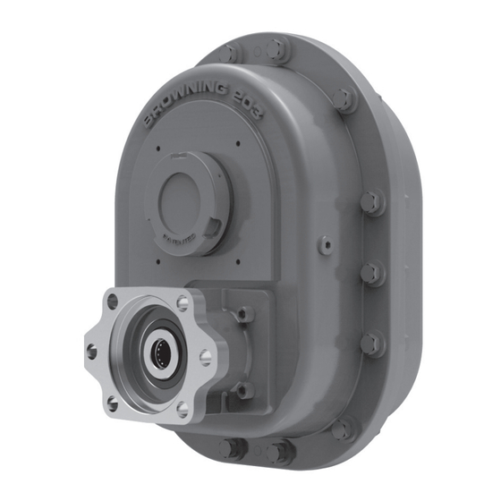
TorqTaper
Plus Helical Shaft Mount
®
Speed Reducers Installation
and Maintenance Manual
• Read and follow all instructions carefully.
• Disconnect and lock-out power before installation and maintenance.
Working on or near energized equipment can result in severe injury or death.
• Do not operate equipment without guards in place. Exposed equipment can
result in severe injury or death.
• Never lift the reducer by the input shaft. Lifting lug should only be used to lift the
weight of the reducer. Do not use lifting lug to lift attached assemblies.
• Reducer shipped without oil. Fill to proper level before operation to avoid
damage and/or personal injury. Do not use lubricants with anti-wear/extreme
pressure additives in units with internal backstops - these additives decrease the
backstops's ability to prevent reverse rotation and will result in backstop failure
which could cause personal injury.
Shaft Mount TorqTaper Plus
Power Transmission Solutions
Regal Beloit America, Inc.
7120 New Buffington Road
Florence, KY 41042
Application Engineering: 800 626 2093
www.RegalPTS.com
• Periodic inspections should be performed. Failure to perform proper maintenance
can result in premature product failure and personal injury.
• All electrical work should be performed by qualified personnel and compliant with
local and national electrical codes.
Hydraulic TorqTaper Plus
F O R M
9191E
Revised
September 2015
C-Face TorqTaper Plus
Advertisement
Table of Contents

Summary of Contents for Regal Browning TorqTaper Plus Series
- Page 1 Power Transmission Solutions F O R M Regal Beloit America, Inc. 9191E 7120 New Buffington Road TorqTaper Plus Helical Shaft Mount ® Florence, KY 41042 Revised Speed Reducers Installation Application Engineering: 800 626 2093 September 2015 www.RegalPTS.com and Maintenance Manual •...
-
Page 2: Table Of Contents
Parts Included with Reducer Lifting Lug Shipped with Breather reducer in a Dirt cover separate bag Spare nylon tipped set screw for end cap Input shaft key End cap Allen wrench Bushing ring for end cap set screw Note: Bushing ring, end cap and dirt cover are installed on the reducer prior to shipment. -
Page 3: Shaft Mount Reducer Installation Instructions
Notice: If the measured values for H and K are less than the tabulated values the Regal Power Transmission Solutions Application Engineering Department at shown in Table 1-5, contact the Regal Power Transmission Solutions Application 1-800-626-2093 before completing the installation. -
Page 4: Rear Mounting Configuration With Stabilizer Ring
Type 2 Bushing Notice: There are three (3) series of bushing keys used in the Type 2 bushing system: rectangular, square and offset. In most cases, the key supplied will be • Position the reducer on the driven shaft with the bushing ring facing out toward the rectangular or offset. -
Page 5: Installation Instructions Finished Bore Model
1.5.3 On the side opposite of the input shaft, thread the bushing ring onto the hollow 1.6.3.4 Rotate the input shaft until the keyway in the hollow output shaft is aligned quill until the bushing ring is flush with the end of the hollow quill. Rotate the reducer with the key “A”, then move the gearbox into position with end of the hollow output shaft input shaft to align the keyway in the hollow quill with the bushing/shaft key. -
Page 6: Oil Level
Notice: TorqTaper seals are grease-packed at assembly. Some purging of grease from around the rotating flingers during initial hours of operation is normal and should be expected. WARNING! Reducer shipped without oil. Fill to proper level before operation to avoid damage and/or personal injury. Do not use lubricants with anti-wear/extreme pressure additives in units with internal backstops - these additives decrease the backstop’s ability to prevent reverse rotation and will result in backstop failure which could cause personal injury. - Page 7 2.1.4 Operating positions may vary as much as 10° from the four positions shown in Figure 2-1 and still have adequate oil by using the indicated oil levels. If it is necessary to vary the operating position less than 10° from these positions, complete the following steps. For reducers operating more than 10° from standard position, contact the Regal Power Transmission Solutions Application Engineering Department at 800-626-2093.
-
Page 8: Relubrication Maintenance Schedule
Table 2-2 B Approximate Oil Capacities in Quarts – Vertical Input Shaft Vertical Output Orientation 9,15, 25, 35:1 Ratio Mounting Position Input Shaft Up Input Shaft Down Input Shaft Up Input Shaft Down 13.0 12.5 12.0 12.0 20.0 20.5 19.0 19.5 26.5 26.5... -
Page 9: Hydraulic And C-Face Motor Mount Installation Instructions
4. Installation Checklist 3. Hydraulic and C-face Motor Mount Installation Instructions 3 Make sure the input shaft rotates properly prior to starting drive. 3.1.1 Before installing the hydraulic motor, measure dimensions A , B, and spline length (SL) on the hydraulic motor. (See Figure 3-1). 3 Never use oils of the EP (extreme pressure) type or those which contain slippery additives, if an internal backstop has been installed. -
Page 10: Shaft Mount Terminology
A material similar to wool fibers that is commonly used in screw Waste pack conveyor applications as a sealing device. Browning and TorqTaper are trademarks of Regal Beloit Corporation or one of its affiliated companies. ©2015 Regal Beloit Corporation, All Rights Reserved. MCIM15015E • Form 9191E • Printed in USA...
Need help?
Do you have a question about the Browning TorqTaper Plus Series and is the answer not in the manual?
Questions and answers