
Related Manuals for Vent-Axia HR205


Summary of Contents for Vent-Axia HR205
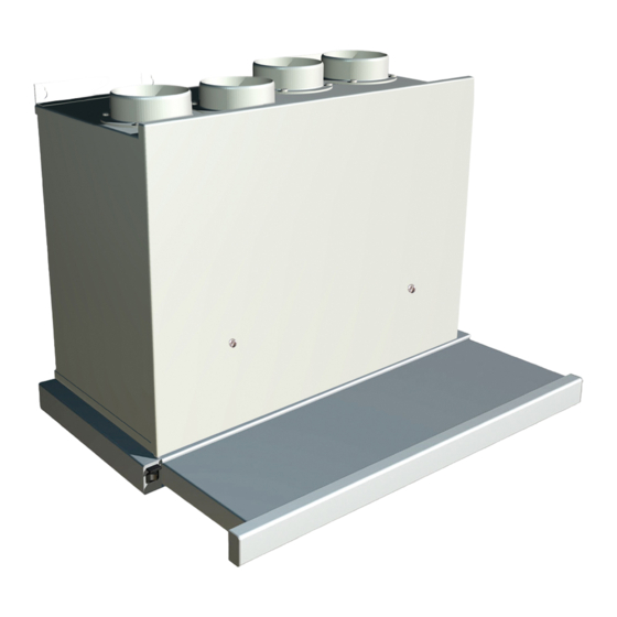
- Page 1 Please leave these instructions with the user Whole House Ventilation System with Heat Recovery and Cooker Hood (HR205) User, Installation & Servicing Instructions...
-
Page 2: Table Of Contents
Contents Section Page User Information General Layout Technical Data Appliance Operation Installation Requirements Installation Wiring Diagrams Commissioning Maintenance 10.0 Changing Components 11.0 Fault Finding 12.0 Short Parts List... -
Page 3: User Information
1.0 User Information The HR204 (Fig. 1) and HR205 (Fig. 2) are whole house ventilation units. This appliance must be installed in accordance with the manufacturers’ instructions and the regulations in force. Duct systems must be installed in accordance with CIBSE guides and BRE Digest 398. - Page 4 • HR205 The HR205 is a mechanical ventilation with heat recovery (MVHR) unit, designed solely to operate with the Vent-Axia telescopic cooker hood. The unit provides continuous extraction of stale air from the dwelling typically from the bathroom and the kitchen.
- Page 5 Take care not to damage the fins. Re-assemble in reverse order after thoroughly drying. Warning Air Inlet Filter - HR204 & HR205 Fig. 4 FRONT 1. Lift off the front door panel by releasing the two hand screws and lifting upwards.
-
Page 6: General Layout
2.0 General Layout HR205 Cover Panels removed for clarity. Heat Exchanger (Lexan) Fire Damper Fan (Fresh Air In) Condensate Drain (15mm) Fan Capacitor (RH) Condensate Tray Electrical Control/Transformer Alternative outlet for condensate Fuse (3.15amp fast blow) Fan (Extraction) Terminal Block... - Page 7 2.0 General Layout HR 204 Cover Panels removed for clarity Heat Exchanger (PVC) Condensate Drain (15mm) Fan (Fresh Air In) Condensate Tray Fan Capacitor (RH) Alternative outlet for condensate (side) Electrical Control/Transformer Fan (Extraction) Fuse (3.15amp fast blow) Fan Capacitor (LH) Terminal Block Inlet Air Filter Lower Fixing Hole...
-
Page 8: Technical Data
3.0 Technical Data HR205 HR204 Including cooker hood Dimensions (mm) Height Width Depth Min. Clearances (mm) Both sides Above casing Below casing Front for servicing Front in operation None None Lift weight (kg) 20.6 16.7 Voltage tappings Power consumption (watts) - Page 9 3.0 Technical Data Flow Rate Vs Pressure Chart 100Pa @ 100m³/Hr The MVHR unit has five normal fan speed settings and one boost 230v setting. The performance 160v curve chart 140v gives the ventilation rates 120v at each fan speed setting compared to the 100v pressure drop...
-
Page 10: Appliance Operation
230 volts and increase the air movement of both exhaust and inlet air. Humidity Sensor • HR205 When the electricity is switched on the unit checks for continuity across the overheat thermostat. The fans then run at the voltage set during commissioning (80,100,120,140 or 160 volts). -
Page 11: Installation Requirements
Site requirements 1. For the HR205 a flat vertical area 1332mm high x 600mm wide is required for installation. For the HR204 a flat vertical area 692mm high x 562mm wide is required for installation. - Page 12 Examples of different ducting & fittings RD015 EV100 Outside RD060 Wall 1.5m NQT100 Bathroom NQT40 IQTB90 RD015 NQT100 NQT40 Terminals minimum SV100 RD060 RD015 NQT100 1m apart IQTB45 Living Room 0.25m NQT100 IFD100 RD070 IQTB45 Fig. 13 HR205...
- Page 13 The pipe should also incorporate a trap with a minimum height of 75mm. See Fig. 17. 2. The HR205 has two alternative condensate Fig. 14 outlet positions: - rear and left hand side . The HR204 has three condensate outlet positions: -...
-
Page 14: Installation
6. Place the MVHR unit on its back (Fig. 15). Lift off the front door panel by releasing the two HR205 hand screws and lifting upwards. 7. Remove the bottom electrical cover by releasing the 3 screws, pulling the panel forwards and disconnecting the earth lead to the panel. - Page 15 6.0 Installation Assembly of the MVHR unit and the cooker hood - HR205 only. 1. Unpack the cooker hood, locate the four Remove screws and washers and the protective box for the cooker hood plug and socket. Cooker Hood 2. Open out the telescopic hood and remove the...
- Page 16 6.0 Installation Fitting the MVHR unit 1. Offer the combined unit to the wall and engage the keyhole slots over the screws previously fitted. 2. Make sure the unit is level and tighten the top screws before engaging the final screw. Making the condensate connection 1.
- Page 17 1. The HR204 requires external controls to enable normal/boost switching, see Page 20 - Wiring Diagrams. Service Wiring 2. The HR205 can have optional external controls fitted, see Pages 18 and 19 - Wiring Diagrams. Making the electrical connection Warning...
-
Page 18: Wiring Diagrams
7.0 Wiring Diagrams HR205 MVHR Unit Wiring (air out) (air in) Key Colors Blue br - Brown gr - Grey g/y - Green/Yellow Purple White bk - Black Controller Overheat Thermostat External Controls Mains Fuse (3.15AT) 230v Earth for To Cooker Hood... - Page 19 7.0 Wiring Diagrams HR205 MVHR Unit Wiring with optional Humidstat HS6 HS6 Humidistat Key Colors Blue br - Brown gr - Grey g/y - Green/Yellow Common Purple Boost White bk - Black Ordinary (air out) (air in) Controller Remove Link...
- Page 20 7.0 Wiring Diagrams HR204 MVHR Unit Wiring (air out) (air in) Key Colors Blue br - Brown gr - Grey g/y - Green/Yellow Purple White bk - Black Controller External Controls External Controls Mains Fuse (3.15AT) 230v Earth for Inspection Panel Fig.
- Page 21 7.0 Wiring Diagrams HR204 MVHR Unit Wiring with optional Humidstat HS6 HS6 Humidistat Key Colors Blue br - Brown gr - Grey g/y - Green/Yellow Common Purple Boost White bk - Black Ordinary (air out) (air in) Controller Mains Fuse (3.15AT) 230v Earth for Inspection...
-
Page 22: Commissioning
8.0 Commissioning Prepare for commissioning - HR205 1. Refit the front door panel by hooking it over the top lip of the appliance and swinging down. Tighten the two case screws. 2. Ensure the telescopic hood is retracted. 3. Turn on the electrical supply. The unit will now start running at the normal ventilation speed. - Page 23 8.0 Commissioning Balancing the system Air Deflector Note: It is important that a suitable Plate anemometer is used to balance the system therefore giving the required Inside View of ventilation rates to each room. Supply Valve Locking Nut to lock 1.
-
Page 24: Maintenance
5. Loosen the two screws on each side plate and covers Warning lift to remove. to inspect LH/RH 6. HR205 only - Check the cooker hood inlet for Fans & debris and fat deposits. Clean as required. Fire FRONT Check the fire damper is in satisfactory condition Damper and unaffected by debris and fat deposits. - Page 25 9.0 Maintenance 13. Turn on the electrical supply to the appliance. With the hood closed the appliance will run on normal setting. Extend the hood and the appliance will switch to boost setting. With the appliance on boost check the operation of the cooker lights 14.
-
Page 26: Changing Components
Controller 10.1 Controller Mounting Controller 1. HR205 Only - Fully extend the telescopic Bracket securing cooker hood and remove the two metal filters. screws (4 off) 2. Remove the outer door by releasing the two Rear View of the Controller screws and lifting the door up and forwards. - Page 27 Service Wiring 4. Slacken the two rear fan bracket screws. 5. Remove the two front fan bracket screws and HR205 remove the fan assembly. Note the position of the fan bracket relative to the fan. 6. Remove the bracket and re-fit to the new fan.
- Page 28 10.0 Changing Components 10.5 Fire damper - HR205 Only 1. Fully extend the telescopic cooker hood. Fire Damper 2. Remove the two metal filters. 3. Remove the outer door by releasing the two screws and lifting the door up and forwards.
- Page 29 This page is intentionally blank...
-
Page 30: Fault Finding
11.0 Fault Finding HR205 - Main Unit Fault Finding Chart Before starting FAULT FINDING Ensure all external controls are operating Refer to diagrams below to carry out preliminary electrical systems checks and are set to normal running. Ensure that identify terminals on components i.e. - Page 31 11.0 Fault Finding HR205 - Main Unit Fault Finding Chart Does the Is there appliance switch adequate airflow to boost when the cooker Do cooker hood Unit operating Replace bulbs at the appliance hood is opened? (Mains lights operate? satisfactorily (Max.
- Page 32 11.0 Fault Finding HR204 - Main Unit Fault Finding Chart Before starting FAULT FINDING Ensure all external controls are operating Refer to diagrams below to carry out preliminary electrical systems checks and are set to normal running. Ensure that identify terminals on components i.e.
- Page 33 11.0 Fault Finding HR204 - Main Unit Fault Finding Chart Is there Do external adequate airflow Unit operating Replace bulbs controls switch at the appliance satisfactorily (Max. 40 watts) the unit to boost. inlets and outlets Clean filter & heat exchanger (section 9).
- Page 34 11.0 Fault Finding Fan Circuit Fault Finding Chart...
-
Page 35: Short Parts List
12.0 Short Parts List o s t Fig. 28 Key No. Spares Part No. Description 372730 Fan assembly c.w. capacitor 372731 Capacitor 372732 Controller 372733 Overheat thermostat 372734 Fire damper 372735 Inlet duct filter 372736 Heat exchanger 372737 Heat exchanger seals (4 off) 372739 Outer door assembly 372741... - Page 36 372705C - 0208...
Need help?
Do you have a question about the HR205 and is the answer not in the manual?
Questions and answers