Table of Contents
Advertisement
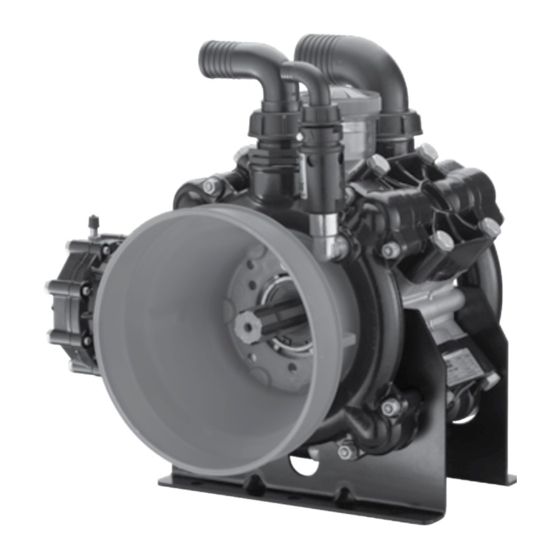
AR 185 bp
NOTICE D'UTILISATION ET INSTALLATION
BETRIEBS- UND INSTALLATIONSANLEITUNG
Dati tecnici e prestazioni - Technical and Performance Data - Données techniques et performances -
Technische Daten und Leistungsmerkmale - Datos técnicos y prestaciones
Portata max
Modello
Model
Max. flow
Modèle
Débit max.
Modell
Max. Fördermenge
Modelo
Caudal máx.
L/1'
l/min
AR 160bp
166,2
AR 160LFP 166,2
182,1
AR 185bp
AR 185LFP 182,1
Istruzioni originali
Original instructions
Notice originale
Originalanleitung
Instrucciones originales
Edizione - Edition - Édition - Ausgabe - Edición: 01/2019
MANUALE D'USO E INSTALLAZIONE
INSTRUCTION MANUAL
MANUAL DE USO E INSTALACIÓN
Pressione max
Max. pressure
Pression max.
Max. Druck
Presión máx.
gpm
bar
psi
U/min
43,9
20
290
43,9
15
218
48,1
20
290
48,1
15
218
AR 160 LFP AR 185 LFP
AR 160 bp
AR 160 LFP
N° giri max
Temperatura max
Max. rpm
Max. temperature
Nbre tours max.
Température max.
Max. Drehzahl
Max. Temperatur
R.p.m. máx.
Temperatura máx.
°C
550
60
550
60
550
60
550
60
N° codice manuale
Manual code no.
N° code de la notice
Kode der Betriebs-und
Installationsanleitung
N° código manual
AR 185 bp
Peso
Weight
Poids
Gewicht
Peso
°F
kg
lb
140
27,5
60,6
140
25
55,1
140
27,5
60,6
140
25
55,1
91401
Advertisement
Table of Contents

Related Manuals for Annovi Reverberi AR 160 LFP


Summary of Contents for Annovi Reverberi AR 160 LFP
- Page 1 AR 160 LFP AR 185 LFP AR 160 bp AR 185 bp AR 185 bp AR 160 LFP MANUALE D’USO E INSTALLAZIONE INSTRUCTION MANUAL NOTICE D’UTILISATION ET INSTALLATION BETRIEBS- UND INSTALLATIONSANLEITUNG MANUAL DE USO E INSTALACIÓN Dati tecnici e prestazioni - Technical and Performance Data - Données techniques et performances - Technische Daten und Leistungsmerkmale - Datos técnicos y prestaciones...
- Page 2 Italiano English Français Deutsch Español...
-
Page 3: Table Of Contents
CONTENTS GENERAL INFORMATION ........................... 22 TECHNICAL INFORMATION ........................24 SAFETY INFORMATION ..........................27 HANDLING AND TRANSPORT INSTRUCTIONS ................... 28 INSTALLATION INSTRUCTIONS ........................ 29 INSTRUCTIONS FOR USE ..........................32 MAINTENANCE INSTRUCTIONS ....................... 33 TROUBLESHOOTING ............................ 37 WARRANTY CONDITIONS............................95 INDEX OF CONTENTS After-Sales service procedures .........23 Residual risks ..............25 Annexed documentation ..........23... -
Page 4: General Information
D) Maximum delivery rate (l/min) E) Maximum operating pressure (bar) F) Maximum rpm G) Lubricant specifications H) Pump code: Manufacturer's name and address Annovi Reverberi Spa Via Martin Luther King, 3 41122 Modena (MO) - Italy English language Use and Installation... -
Page 5: After-Sales Service Procedures
GENERAL INFORMATION After-Sales service procedures To request after-sales service (in the event of a pump malfunction or failure, etc.) contact your nearest service centre or the manufacturer. When requesting after-sales services, always state the pump's data plate data and the type of problem. Disclaimer The manufacturer accepts no liability arising from: - incorrect installation;... -
Page 6: Technical Information
TECHNICAL INFORMATION General description The pump is designed and constructed to pump and compress liquids on spraying machines for the protective treatment of agricultural crops and garden plants. The pump incorporates radial pistons which actuate the diaphragms by means of an oil cushion. The dia- phragms are connected to the pistons in their middles by means of plates and secured at the edges between the cylinder liner and head. -
Page 7: Residual Risks
TECHNICAL INFORMATION Intended uses The pump is designed and constructed for incorporation in plants and machinery (spraying machines for the protective treatment of agricultural crops and garden plants). All other uses constitute misuse unless ap- proved by the manufacturer's technical service The pump must be used in a manner appropriate to its technical data (see “Technical Data”), and must not be modified or improperly used. -
Page 8: Declaration Of Incorporation
Reverberi Ing. Stefano Managing Director Modena 20/03/2017 Annovi Reverberi S.p.A. Via Martin Luther King, 3 – 41122 Modena (MO) – Italia Tel. +39 059 414 411 – Fax +39 059 253 505 – E-Mail : infoar@annovireverberi.it – Web : www.annovireverberi.it... -
Page 9: Safety Information
SAFETY INFORMATION General safety rules Most workplace accidents and injuries are caused by carelessness and failure to comply with common sense and safety rules. In most cases, accidents can be avoided by predicting their possible causes and proceeding with the necessary care and attention. -
Page 10: Handling And Transport Instructions
HANDLING AND TRANSPORT INSTRUCTIONS Safety recommendations for handling and lifting Before starting the operations, organise the intended working area so that the materials can be lifted and handled in safety. Unloading, loading, handling and lifting operations must be carried out by skilled, authorised, specifi- cally trained staff. -
Page 11: Installation Instructions
INSTALLATION INSTRUCTIONS Installation The mechanical connection between the pump and the motive power source may be made by means of a pul- ley and belt, with a drive shaft, or through a direct flanged connection to the motive power source. The crankshaft may turn in either direction. -
Page 12: Connection
INSTALLATION INSTRUCTIONS General guidelines on water supply connection To operate correctly, the diaphragm pump must draw in liquids from containers at atmospheric pressure. Do not supply the pump with pressurised liquids. For continuous duty, the pump should not draw in water by gravity from containers with liquid level at heights above 3 m. -
Page 13: Installation Diagram (Guideline)
INSTALLATION INSTRUCTIONS Installation diagram (guideline) The following is a simplified illustration of the typical installation layout and is purely guideline. Distributor by-pass Tank Agitation Relief valve by-pass Distributor Intake lter Pump Delivery line lter UN003414-EW English language Use and Installation... -
Page 14: Instructions For Use
INSTRUCTIONS FOR USE Safety recommendations for use Before start-up, the operator must perform the necessary safety checks. In the event of leaks from the pressurised pipes, stop the pump at once and remove the cause of the leak. Do not operate the pump above the limits set by the manufacturer to increase its performance. Preliminary checks If the pump has a pressure accumulator, check its level of inflation, see “Checking the inflation pressure”. -
Page 15: Maintenance Instructions
MAINTENANCE INSTRUCTIONS Safety recommendations for maintenance Caution - Take Care Before doing any maintenance work, depressurise the water system and isolate the pump from all en- ergy sources. When the jobs are done, before restarting the pump, check that no tools, rags or other materials have been left close to moving parts or in hazardous zones. -
Page 16: Checking The Oil Level
MAINTENANCE INSTRUCTIONS Table of lubricants The pump is delivered complete with high-performance synthetic multigrade oil suitable for the intended ambient conditions (see “Environmental operating limits”). Inspecting the pump mounting Check that the pump's fixing screws have not become loose. If necessary, tighten them with the driving torque stated in the installation design. Inspecting the connections and pipes - Inspect the connections for leaks. -
Page 17: Checking The Inflation Pressure
MAINTENANCE INSTRUCTIONS Checking the inflation pressure If the pump has a pressure accumulator, check its level of inflation, with the pump at a standstill, us- ing an air gun fitted with a pressure gauge. The ac- cumulator is inflated by the manufacturer for use of the pump at its maximum pressure. -
Page 18: Scrapping The Pump
MAINTENANCE INSTRUCTIONS Lengthy pump lay-offs It is important to comply with the recommendations for lay-offs in the operator's manual of the machine into which the pump is incorporated. For the pump itself, at the end of pumping operations it is essential to flush out the internal circuit by pump- ing clean water. -
Page 19: Troubleshooting
TROUBLESHOOTING The information provided is intended to provide guidance how to deal with malfunctions which may occur during use. Some of these procedures may be carried out by skilled staff, while others have to be performed at specialised service centres since they require the use of specific equipment as well as detailed knowledge of repair opera- tions. - Page 20 TROUBLESHOOTING Problem Cause Remedy Oil seal on pump Replace the worn oil seal. (1) shaft worn. Oil on pump body or base. Oil pressure inside pump too high. Restore correct oil level in tank. Pump using too much oil (oil flowing from delivery port) or oil Stop the pump at once.
Need help?
Do you have a question about the AR 160 LFP and is the answer not in the manual?
Questions and answers