Table of Contents
Advertisement
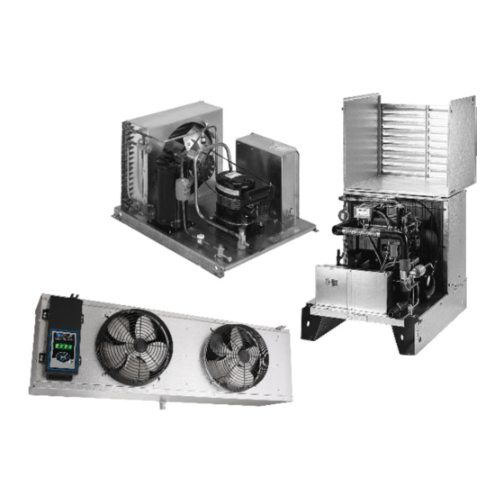
Condensing Unit and
Refrigeration System
Installation & Operations Manual
908 Highway 15 North
New Albany, MS 38652
Phone: 800-684-8988
Fax: 800-232-3966
www.master-bilt.com
©2015 Master-Bilt Products, an unincorporated division of Standex International Corporation.
All rights reserved.
5/16 Rev. B 57-02497
Advertisement
Table of Contents

Summary of Contents for Standex Master-Bilt B-SERIES
- Page 1 Condensing Unit and Refrigeration System Installation & Operations Manual 908 Highway 15 North New Albany, MS 38652 Phone: 800-684-8988 Fax: 800-232-3966 www.master-bilt.com ©2015 Master-Bilt Products, an unincorporated division of Standex International Corporation. All rights reserved. 5/16 Rev. B 57-02497...
-
Page 2: Table Of Contents
TABLE OF CONTENTS INTRODUCTION.............................3 WARNING LABELS AND SAFETY INSTRUCTIONS...............4 B-SERIES CONDENSING UNIT FEATURES..................5 M-SERIES CONDENSING UNIT FEATURES……................6 MASTER-BILT REFRIGERATION NOMENCLATURE..............7 PRE-INSTALLATION..........................8 INSTRUCTIONS............................8 General Information……........................8 Delivery Inspection…..........................8 INSTALLATION INSTRUCTIONS.......................8 Handling and Placement of Condensing Unit..................8 Handling and Placement of Evaporator Coil in Walk-In ...............9 Evaporator and Drain line installation Instructions…………..…………………………………9-10 Electrical…………..........................11 Refrigerant Piping……………......................11... -
Page 3: Introduction
INTRODUCTION ® Thank you for purchasing Master-Bilt refrigeration equipment. This manual contains important instructions for installation, use and service. Read all of this manual carefully before installing or ® servicing your Master-Bilt refrigeration equipment. NOTICE Installation and service of the refrigeration and electrical components must be performed by a refrigeration mechanic or licensed electrician. -
Page 4: Warning Labels And Safety Instructions
WARNING LABELS AND SAFETY INSTRUCTIONS This is the safety-alert symbol. When you see this symbol, be alert to the potential for personal injury or damage to your equipment. Be sure you understand all safety messages and always follow recommended precautions and safe operating practices. -
Page 5: B-Series Condensing Unit Features
B-SERIES CONDENSING UNIT FEATURES STANDARD COMPONENTS The B-Series units offer the most complete set of standard features (pre-wired and mounted except as noted)* These include: ● Liquid line and suction line vibration absorbers (eliminators) for semi-hermetic units only. ● Adjustable dual pressure control ●... -
Page 6: M-Series Condensing Unit Features
M-SERIES CONDENSING UNIT FEATURES STANDARD COMPONENTS The M-Series set of standard features (pre-wired and mounted except as noted)* include: ● Liquid line and suction line vibration absorbers (eliminators) for semi-hermetic units only ● Preset non-adjustable high pressure control and preset non-adjustable low pressure control** ●... -
Page 7: Master-Bilt Refrigeration Nomenclature
® MASTER-BILT REFRIGERATION NOMENCLATURE MODEL NUMBER EXPLANATION (CONVENTIONAL = ACCESSIBLE HERMETIC) BC = Built-up Remote Conventional Condensing Unit MH = Hermetic Condensing Unit BH = Built-up Remote Hermetic Condensing Unit MS = Scroll Condensing Unit BS = Built-up Remote Scroll Condensing Unit MD = Discus Condensing Unit MC = Conventional Condensing Unit ROOM TEMPERATURE EXPLANATION... -
Page 8: Pre-Installation
PRE-INSTALLATION INSTRUCTIONS I. General Information ® Please read this manual prior to installing your Master-Bilt equipment. This information is based on good refrigeration practice and should be used as a guide for installation and operation. To complete the installation, please records the data requested on the Installation Data form on page 35 of the manual and return this manual to the owner. -
Page 9: Handling And Placement Of Evaporator Coil In Walk-In
II. Handling and Placement of Evaporator Coil in Walk-In To minimize damage to the evaporator coil, it is recommended that the carton (or crate) not be removed until the evaporator coil is moved close to its final location. When the container is removed from the evaporator coil, extreme care must be used when lifting and mounting to the ceiling, to prevent sheet metal damage. - Page 10 EVAPORATOR DRAIN LINE INSTALLATION: a. Copper lines must be used for drains. Plastics are not acceptable. b. Drain lines must exit the freezer or cooler as quickly as possible and must have a pitch of at least 1/8” inch/foot downward or meet the local code requirements. c.
-
Page 11: Electrical
III. Electrical Electric power supply must match the condensing unit power requirements indicated on the unit data plate. A WIRING DIAGRAM IS LOCATED ON THE INSIDE OF THE ELECTRICAL BOX COVER. All field wiring may enter the holes provided in left side, back and bottom of the electrical box. -
Page 12: Leak Check
NOTICE Be sure solenoid valves are open before beginning evacuation and leak check. v. Leak Check When all refrigeration line connections have been made, the complete system, including factory connections, should be leak checked. Add the proper refrigerant to 60 psig, then boost to 175 psig with dry nitrogen. Leak checks all joints with an electronic leak detector or a halide torch. -
Page 13: Finish Charging Procedures
FINISH CHARGING PROCEDURES A. Preliminary Be sure all service valves are “open”. Loose the compressor hold-down bolts and remove shipping clips to allow compressor to float freely on the springs. Check evaporator fan motors after start-up. Medium temperature, air defrosts fans run continuously. Low temperature fans and coolers provided with electric defrost will be delayed by the fan control. -
Page 14: Pre-Charged Remote Refrigeration Systems
Technical installation instructions for Pre-Charged Remote Refrigeration are given on the following pages. Installation requirements for other remote refrigeration systems may vary. If additional information is needed, your certified refrigeration mechanic or electrician can call Master-Bilt at 800-684-8988. Quick-Couples are pre-charged with the proper refrigerant at the factory. D. - Page 15 Connect correctly rated over current protection device in the service line to the service line J- ● box on the condensing unit. After routing condensate line from drain pan of evaporator coil, seal around all refrigeration, ● electrical and drain lines with silicone or butyl caulking. ●...
-
Page 16: Final Check List For All Models
VII. Final Check List for All Models A. Check high-low pressure control settings. B. Check setting of defrost timer: Medium temperature 2 to 4 defrosts/24 hours, with 35 minutes fail safe. Low temperature 3 to 4 defrosts/24 hours, with 44 minutes fail safe. C. -
Page 17: R-404A Suction And Liquid Line Sizes
NOTE: Sizes specified are for Type "L" copper tubing. 5/16 Rev. B 57-02497... - Page 18 NOTE: Sizes specified are for Type "L" copper tubing. 5/16 Rev. B 57-02497...
-
Page 19: Equivalent Length Allowance For Fittings
EQUIVALENT LENGTH ALLOWANCE FOR FITTINGS EQUIVALENT LENGTH IN FEET FITTING 90° 45° SIZE (Line) (Branch) 1/2" 5/8" 7/8" 1-1/8" 1-3/8" 1-5/8" 2-1/8" 10.0 Chart A GENERAL: Suction lines should be pitched down in direction of flow, 1/2" per 10 feet of line. Refrigerant lines should be supported and fastened properly to prevent leaks and for professional looking installation. -
Page 20: Low Ambient Operation Charge
LOW AMBIENT OPERATION CHARGE ® Some Master-Bilt units are provided with condenser flooding valves to maintain proper head pressure during the winter. These valves function by reducing the effective condenser area by flooding or “backing up” refrigerant in the condenser to reduce the amount of surface available for condensing. - Page 21 5/16 Rev. B 57-02497...
-
Page 22: Condensing Unit Specifications
CONDENSING UNIT SPECIFICATIONS Base BTU/HR Capacity At Size Room Temp. With a (See 10° TD, 90° Ambient Connections Master-Bilt ® Cond Unit/Comp Compressor Model Model Model Ref. 39-41) Liquid Suction Voltage BCHX0050B E3AH-A050-CAV HAG2-0050-CAV 4059 4510 R-22 208-230/60/1 BCHX0070B E3AH-A075-CAV KAE2-0075-CAV 6084 6760... - Page 23 CONDENSING UNIT SPECIFICATIONS (cont.) Base BTU/HR Capacity At Size Room Temp. With a (See 10° TD, 90° Ambient Connections Master-Bilt Cond Unit/Comp Compressor Model Model Model Ref. 39-41) H.P. Liquid Suction Voltage BCHY0100C KAJA-011E-TAC KAJA-011E-TAC 7650 8500 R134a 208-230/60/3 BCHY0150C KALA-016E-TAC KALA-016E-TAC 10800...
- Page 24 CONDENSING UNIT SPECIFICATIONS (cont.) BTU/HR Capacity At Base Room Temp. With a 10° Size TD, 90° Ambient Connections Master-Bilt ® Cond Unit/Comp Compressor (See pp. Model Model Model Ref. 39-41) H.P. Liquid Suction Voltage BCLX030DC 2DF3-0300-TFC 2DF3-0300-TFC 11750 15865 21029 R-22 1 3/8 208-230/60/3...
- Page 25 *Deduct 7% for each 10 degree rise over 90°F. **MCA does not include evaporator amps for room temperature 35°F and above. CONDENSING UNIT SPECIFICATIONS (cont.) Base BTU/HR Capacity At Size Room Temp. With a 10° (See TD, 90° Ambient Connections Master-Bilt ®...
- Page 26 CONDENSING UNIT SPECIFICATIONS (cont.) Base BTU/HR Capacity At Size Room Temp. With a (See 10° TD, 90° Ambient Connections Master-Bilt ® Cond Unit/Comp Compressor Model Model Model Ref. 39-41) H.P. Liquid Suction Voltage BCMX0070B E3AM-A075-CAV KAE2-0075-CAV 6410 R-22 208-230/60/1 BCMX0070C E3AM-A075-TAC KAEA-0075-TAC 6410...
- Page 27 CONDENSING UNIT SPECIFICATIONS (cont.) BTU/HR Capacity At Base Room Temp. With a Size 10° TD, 90° Ambient Connections (See Master-Bilt ® Cond Unit/Comp Compressor Model Model Model Ref. 39-41) H.P. Liquid Suction Voltage BCMZ0200CC ERCA-021E-TAC ERCA-021E-TAC 17611 R-404A 208-230/60/3 BCMZ0300B ERFB-031E-CAB ERFB-031E-CAB 24892...
- Page 28 CONDENSING UNIT SPECIFICATIONS (cont.) BTU/HR Capacity Base At Room Temp. Size With a 10° TD, 90° (See Master-Bilt ® Cond Unit/Comp Compressor Ambient Connections Model Model Model Ref. 39-41) H.P. Liquid Suction Voltage BHH-030VCC CR41KQ-TF5 CR41KQ-TF5 26966 29962 R-22 200-230/60/3 BHH-050VCC CRN5-0500-TF5 CRN5-0500-TF5...
- Page 29 *Deduct 7% for each 10 degree rise over 90°F. **MCA does not include evaporator amps for room temperature 35°F and above. CONDENSING UNIT SPECIFICATIONS (cont.) BTU/HR Capacity Base At Room Temp. Size With a 10° TD, 90° (See Master-Bilt ® Ambient Connections Cond Unit/Comp...
- Page 30 CONDENSING UNIT SPECIFICATIONS (cont.) Base BTU/HR Capacity Size At Room Temp. With (See a 10° TD, 90° Ambient Connections Master-Bilt ® Cond Unit/Comp Compressor Model Model Model Ref. 39-41) H.P. Liquid Suction Voltage BHM-025NC CRG3-0250-TF5 CRG3-0250-TF5 17907 R-22 200-230/60/3 BHM-050VCC CRN5-0500-TF5 CRN5-0500-TF5 38129...
- Page 31 CONDENSING UNIT SPECIFICATIONS (cont.) Base BTU/HR Capacity At Size Room Temp. With a 10° (See TD, 90° Ambient Connections Master-Bilt ® Cond Unit/Comp Compressor Model Model Model Ref. 39-41) H.P. Liquid Suction Voltage BSHX020VCC ZB15KCE-TF5 ZB15KCE-TF5 18000 20000 R-22 200-230/60/3 BSHX020VCW ZB15KCE-TF5 ZB15KCE-TF5...
- Page 32 CONDENSING UNIT SPECIFICATIONS (cont.) Base BTU/HR Capacity At Size Room Temp. With a (See 10° TD, 90° Ambient Connections Master-Bilt ® Cond Unit/Comp Model Model Compressor Model Ref. 39-41) H.P. Liquid Suction Voltage BSLZ0200C ZF06K4E-TF5 ZF06K4E-TF5 5994 7535 9250 R-404A 200-230/60/3 BSLZ028VCC ZF13K4E-TF5...
- Page 33 CONDENSING UNIT SPECIFICATIONS (cont.) Base BTU/HR Capacity At Size Room Temp. With a (See 10° TD, 90° Ambient Connections Master-Bilt ® Cond Unit/Comp Compressor Model Model Model Ref. 39-41) H.P. Liquid Suction Voltage BSMX0200C ZB15KCE-TF5 ZB15KCE-TF5 16000 18000 20000 R-22 200-230/60/3 BSMX020VCN ZS15K4E-TF5...
- Page 34 CONDENSING UNIT SPECIFICATIONS (cont.) Base BTU/HR Capacity At Size Room Temp. With a (See 10° TD, 90° Ambient Connections Master-Bilt ® Cond Unit/Comp Compressor Model Model Model Ref. 39-41) H.P. Liquid Suction Voltage MCHX0061B HAG2-0050-CAV HAG2-0050-CAV 3947 4441 4965 R-22 208-230/60/1 MCHX0081B KAN2-0075-CAV...
- Page 35 CONDENSING UNIT SPECIFICATIONS (cont.) Base BTU/HR Capacity At Size Room Temp. With a (See 10° TD, 90° Ambient Connections Master-Bilt ® Cond Unit/Comp Compressor pp. 39- Model Model Model Ref. H.P. Liquid Suction Voltage MCLZ0021B KANB-005E-CAV KANB-005E-CAV 1249 1911 2719 R-404A 208-230/60/1 MCLZ0031B KAMB-007E-CAV...
- Page 36 CONDENSING UNIT SPECIFICATIONS (cont.) BTU/HR Capacity At Room Base Temp. With a 10° TD, 90° Size Master-Bilt ® Ambient Connections Cond Unit/Comp Compressor (See pp. Model Model Model Ref. 39-41) H.P. Liquid Suction Voltage MHHX0051B ART82C1-IAV-201 ART82C1-CAV-201 3930 5040 5690 6430 R-22 208-230/60/1 MHHX0075B RS64C2-IAV-201...
- Page 37 *Deduct 7% for each 10 degree rise over 90°F. **MCA does not include evaporator amps for room temperature 35°F and above. CONDENSING UNIT SPECIFICATIONS (cont.) BTU/HR Capacity At Room Base Temp. With a 10° TD, 90° Size Ambient (See Connections Master-Bilt ®...
- Page 38 MHHZ0501B CS33K6E-PFV CS33K6E-PFV 30884 39545 44031 48868 R-404A 1 3/8 208-230/60/1 MHHZ0501BM CS33K6E-PFV CS33K6E-PFV 30884 39545 44031 48868 R-404A 1 3/8 208-230/60/1 MHHZ0501C CS33K6E-TF5 CS33K6E-TF5 30487 39036 43433 48384 R-404A 1 3/8 200-230/60/3 MHHZ0501CM CS33K6E-TF5 CS33K6E-TF5 30487 39036 43433 48384 R-404A 1 3/8 200-230/60/3 MHHZ050CC...
-
Page 39: Condensing Unit Specifications
CONDENSING UNIT SPECIFICATIONS (cont.) Base BTU/HR Capacity At Room Size Temp. With a 10° TD, 90° Cond (See Master-Bilt ® Ambient Connections Unit/Comp Compressor Model Model Model Ref. 39-41) H.P. Liquid Suction Voltage MSHX0201B ZB15KCE-PFV ZB15KCE-PFV 14539 17930 19707 21647 R-22 200-230/60/1 MSHX0201C... -
Page 40: Unit Base Specifications
UNIT BASE SPECIFICATIONS 5/16 Rev. B 57-02497... - Page 41 UNIT BASE SPECIFICATIONS (CONT.) 5/16 Rev. B 57-02497...
-
Page 42: Unit Base Specifications
UNIT BASE SPECIFICATIONS (CONT.) 5/16 Rev. B 57-02497... -
Page 43: Sale And Disposal
SALE AND DISPOSAL If you sell or give away your walk-in refrigeration system or components you must make sure that all safety labels and the Refrigeration Unit Installation and Operations Manual are included. If you need replacement labels or manuals, contact the parts and technical service department at Master-Bilt at 800- 684-8988. -
Page 44: Installation Data
INSTALLATION DATA Date System Installed __________________________________________________________________ ____________________________________________________________________________________ ____________________________________________________________________________________ Installer and Address ____________________________________________________________________________________ ____________________________________________________________________________________ ____________________________________________________________________________________ Phone: _______________________________ Condensing Unit Model_________________________ Serial _________________________ Electrical ______________________ Volts _____________________ Phase _____________________ Evaporator(s) Quantity_______________________ Model_________________________ Serial__________________________ Thermostat Setting ____________________°F Defrost Setting _______________________ /24 hrs. __________________ Min. Fail Safe Electrical __________________ Volts _______________ Amps Operating Pressures _______________ Suction _______________ Discharge 5/16 Rev. - Page 45 ©2015 Master-Bilt Products, an unincorporated division of Standex International Corporation. All rights reserved. 5/16 Rev. B 57-02497...
Need help?
Do you have a question about the Master-Bilt B-SERIES and is the answer not in the manual?
Questions and answers