Advertisement
Quick Links
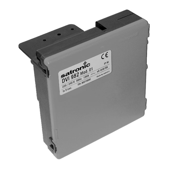
Gas Burner Safety Control
For 1- or 2-stage forced draught and
atmospheric gas burners, with DC valves
Possible flame detectors:
- Ionisation probe
- Infrared flicker detector 1020.1
- UV flame sensor UVD 971
INTRODUCTION
The burner control boxes DVI980/982 controls and
supervises forced draught and atmospheric gasburners.
They are approved and certified according to the applicable
European standards and regulations. The use on direct air
heaters according DIN 4794 is also possible.
The microprocessor-based programming sequence ensures
extremely stable timings independent of voltage variations,
ambient temperature and/or switch-on cycles. The built-in
information system not only provides a continuous
monitoring of the actual state of the box (very helpful
especially for monitoring the start-up phase) but also informs
about the cause of a possible lock out. The lock out cause
is stored in such a way that it can be retrieved even after a
power failure. The control box is designed for maximum
safety in case of fluctuations in the voltage supply. If the
mains voltage drops below the permitted level, operation is
interrupted and the control box automatically prevents the
start sequence from being repeated. In this way, the safety
of the system is not put at risk by a drop in the mains voltage.
This low-voltage protection works not only during start-up
but also permanently during operation.
CONSTRUCTION FEATURES
Microprocessor, electronic components, output relais,
ignition spark generator and flame amplifier are placed on
the printed circuit board.
These plus the optional lockout- and reset circuit are well
protected inside a flame resistant plastic housing.
The LED for displaying the information system are placed
on top of the housing.
TYPES AVAILABLE
DVI 980
1-stage
DVI 982
2-stage
MODELS
The following functions can be configured by factory:
•
with or without air proving switch
•
IR-data transmission over Palm Pilot, PC or hand-held
•
volatile or non volatile lock out
•
recycling (numbers eligible) or lock out / blocked after
loss-of-flame during operation
•
recycling (numbers eligible) or lock out / blocked without
flame establishment after safety time
•
with or without internal reset button
•
potential free output for flame signal
•
with or without lock out lamp (LED)
Table of timings (sec.)
Model
max. reaction time or
air proving switch
tlw
01
60
02
60
05
60
A Honeywell Company
supervised
pre-ignition
pre-purge time
time
tv1
tvz
24
0
10
0
30
0
1
DVI 980/982
(Honeywell Nr. S4865)
TECHNICAL DATA
Operating voltage
Fuse rating
Power consumption
Max. load per output
- term. X2/6 motor
Variation A
- term. X3 ,X5, X6 solenoid valves
Variation B
- term. X3, X9, X5, X6 solenoid valves 90mA, DC
only DC-valves can be connected!
- term. X2/8 lock out
total load
Air proving switch
STB Safety temperature delimiter
Ignition spark generator
Ignition frequency
Energy ignition spark
Ignition voltage
Sensitivity (operation)
Min. required ion. current
Sensitivity for stray light
Flame signal output
Ionisation probe insulation
Stray capacity
Cable length
Flame detectors
IRD 1020.1
UVD 971
Weight incl. Wiring base
Mounting position
Protection class
Approved ambient parameter
- for operation
- for storage
Build-up of ice, penetration of water and condensing water
are inadmissible
Approvals according
ignition time
stray light
total
monitoring
tz
tf
4
5
4
5
4
5
220 / 240 V (-15... +10%)
50/60 Hz (±5%)
10 A fast, 6 A slow
ca. 12 VA
2.0 A, cos ϕ 0.4
90mA, DC
1.0 A, cos ϕ 0.4
max. 6 A during 0,5 sec
1 working contact
1 working contact
up to 40 Hz
10 µAs
20 kV
1 µA
1.5 µA
0.4µA
Optocoupler
max 70V DC/100mA
Probe - earth
greater than 50 MΩ
Probe - earth
less than 1000 pF
< 3 m
end-on viewing
end-on viewing
190 g
any
IP 40
-20° C... +60° C
-20° C... +80° C
to European standard
EN 298, as well as all other
relevant Directives and
standards
safety time
delay 2nd stage
(DVI 982)
ts
tv2
5
10
5
–
5
–
Advertisement

Related Manuals for Honeywell Satronic DVI 980


Summary of Contents for Honeywell Satronic DVI 980
- Page 1 DVI 980/982 A Honeywell Company (Honeywell Nr. S4865) Gas Burner Safety Control For 1- or 2-stage forced draught and atmospheric gas burners, with DC valves Possible flame detectors: - Ionisation probe - Infrared flicker detector 1020.1 - UV flame sensor UVD 971...
-
Page 2: Application Features
APPLICATION FEATURES 1.2 Lock-out diagnoses 1. Information system In case of a failure the LED is permanently illuminated. Every 10 seconds the illumination is interrupted by a flash code, The information system is microprocessor based and reports which indicates the cause of the error. Therefore the following on all aspects of burner control box operation and flame sequence is performed which is repeated as long as the unit supervision. - Page 3 3. Lock out and reset 6. Mounting and electrical wiring The unit can be reset or brought into lock out mode in two The DVI 980/982 is put directly on the solenoid valve. different ways: Molex plug connector 3003 for: –...
- Page 4 INSTALLATION INSTRUCTIONS AND MAINTENANCE 3. Fault finding 1. Important notes The built-in information system facilitates the trouble shooting in the case of problems occurring during start-up – The controls must be installed by qualified personnel or during operation. only. The relevant national regulations have to be A list of possible lock out messages can be found in observed.
- Page 5 CIRCUIT AND TIMING DIAGRAM DVI 980/982 Using only the connection diagram for the wiring which is noted down for the respective model variation (see "7. model functions", page 3). A wrong wiring leads to malfunctions! Valve supply not over air proving switch contact max.
-
Page 6: Ordering Information
Plug-type, 3-core cable, 0.6 m with tag wire end 7236001 The above ordering information refers to the standard version. Special versions are also included in our product range. Specifications subject to change without notice DVI 980/982 A Honeywell Company Satronic AG Honeywell-Platz 1 Postfach 324 CH-8157 Dielsdorf...
Need help?
Do you have a question about the Satronic DVI 980 and is the answer not in the manual?
Questions and answers