Table of Contents
Advertisement
Advertisement
Table of Contents

Summary of Contents for Tarfire SF-2200H-QG
- Page 1 Flame/Plasma CNC Cutting System SF-2200H-QG (V2.1) Operating Manual...
- Page 2 Contents System Functions Overview System Operating Menu Auto Function Edit Function Command Function Figures Setting Graphic Libraries Diagnose Functions System Input / Output Interface Appendix: 1. Exterior Dimension 2. Software Upgrade Instruction...
- Page 3 Please read carefully this manual before use the system. Attention 1) After open the packing case, please check the goods and whether accord with the list. 2) This manual is only for Portable Flame/Plasma cutting machine system produced by Beijing Start Microstep. 3) Operating environment temperature is 0-40℃.
- Page 4 7) The inside power source of CNC system does not allow connecting with other electric apparatus. 8) Toward some area that power supply is nonstandard (such as zero line and earth wire sharing or no zero line), in order to ensure control system working normally and improve system reliability and sure operator’s safety, you must use isolation transformer that three-phase/two-phase AC380V transfer to two- phase AC220v between electric network and control system.
-
Page 5: Table Of Contents
Contents SECTION 1 Overview------------------------------------------------------------------------------------------4 1.1Function--------------------------------------------------------------------------------------------------------4 1.2Features--------------------------------------------------------------------------------------------------------4 1.3Hardware Specifications-------------------------------------------------------------------------------------4 1.4Control panel illustration---------------------------------------------------------------------------------------5 1.5Connecting Instruction-----------------------------------------------------------------------------------------6 SECTION 2 Main Menu-----------------------------------------------------------------------------------------7 SECTION 3 Auto Function-----------------------------------------------------------------------------------8 3.1Auto menu instruction--------------------------------------------------------------------------------------8 3.2Function-------------------------------------------------------------------------------------------------------9 3.3Speed Mode and auto cutting------------------------------------------------------------------------------9 3.4Control and Compensate during Auto cutting-------------------------------------------------------10 3.5Break resume and power down come back---------------------------------------------------------11 3.6Select Segment function---------------------------------------------------------------------------------11 3.7Extend pierce----------------------------------------------------------------------------------------------- 12 SECTION 4 Edit------------------------------------------------------------------------------------------------13... -
Page 6: Section 1 Overview
Section 1 System Overview 1.1 System Function SF-2200H-QG Flame/Plasma CNC cutting machine system is a desirable control system suits the needs of both flame and plasma cutting. The operating display by system adopt windows hint step by step under main menu, after press one function key, system will display the sub-menu. -
Page 7: Control Panel Illustration
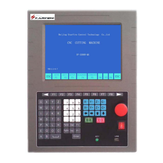
1.4、System Panel Instruction Label 10.4" LCD Display Programming and operating Emergency keypad Button Power Switch PC keyboard interface Interface Rear Lock Power supply Input Earth Interface Output Insurance tube Motor Motor X, SF-2200H Flame / Plasma CNC Cutting System Operating Manual... -
Page 8: Connecting Instruction
1.5、Connection Instruction AC220 AC220 SF-2200H Flame / Plasma CNC Cutting System Operating Manual... -
Page 9: Section 2 Main Menu
Section 2 Main Menu 2.1、Menu Features Menu display applies step-by-step hint style. Under the main menu, system loads all the available functions after entering the sub-menu. Follow the hints that windows displays, press 【F1】 to 【F8】 to choose desired functions, press ESC to abort and return to upper level menu. 图... -
Page 10: Section 3 Auto Function
Section 3 Auto Function Under main menu, press [F1] to enter Auto Function menu,shown as below: Strong Current Strong Current Command Hole No. Output File Name and Compensation Current Speed Operating hint Graphic Display Input output display Coordinates Cutting Parameters Function Menu Auto Function Menu 3.1、Auto menu instruction... -
Page 11: Speed Mode And Auto Cutting
【F4】VIEW: Check whether the graphic program loaded is correct. 【F5】MIRR: Program runs as mirror image, default is non-mirror mode. 【F6】SCALE: Enlarge or reduce the display size of cutting shape. 【F7】ROTATE: Rotate the angle of cutting. 【F8】ASSI: Assist users to perform additional functions. 3.2.1【F8】ASSI 【F8】... -
Page 12: Control And Compensate During Auto Cutting
3.3.4、Auto Mode Ignition 1) Before auto cutting starts To select proper cutting program, choose the suitable cutting speed ratio. Put torch on the cutting position (Torch will be lifted up after program initializes (executes M70) ) ,after other preparation works are done, the program may start auto mode execution. 2) Two ways to initialize auto mode: a) Green 【START】... -
Page 13: Break Resume And Power Down Come Back
3.5、Break point processing 3.5.1. Break point resume When system is in pause or accidentally power off; system saves current torch position as a break point. The break point is permanent whether system is turned off or not. Under auto mode, as long as the cutting program does not change, press 【F2】 select break point function, then press 【START】... -
Page 14: Extend Pierce
图 3.5 selections Menu Meanwhile:use 【↑】 【↓】 to move the curser to choose either SELECT mode to cut According to the choice, system would choose order number to process. 3.7、Edge piercing of thick sheet In auto mode, edge piercing is more suitable for thick sheet. Solution of edge piercing:Move the torch to sheet edge before piercing. -
Page 15: Section 4 Edit
SECTION 4 Edit Function press 【F2】 to enter Edit mode. System displays the following 4) Under system main menu, picture. 图 4.1Edit mode main menu 4.1、Edit Mode Menu 4.1.1【F1】New Create new program, clear out cutting edit area and starting editing a new cutting program. 4.1.2【F2】Load Load in any existing cutting program into the system, press 【ESC】... - Page 16 图 4.2 Removable disk option menu 【F1】Load program file from removable disk to system; 【F2】Load program file from system to removable disk 4.1.7、 【F7】Find Parameters This function is currently unavailable, saved for future upgrades. SF-2200H Flame / Plasma CNC Cutting System Operating Manual...
-
Page 17: Section 5 Commanding System
SECTION 5 Commanding System 5.1、 Programming symbol Every action of CNC machine running according to regulate program, every machine program be composed instruction segment Function word of some , and every instruction segment be composed of some each function word must start by letter, parameter follow. Definition of function word: N--The No of instruction segment G--Prepare function... -
Page 18: Section 6 Parameter Setup
Section 6 Parameter Setting Under system main menu, press 【F3】to enter display interface as below:: 图 6.1Parameter setting main menu 6.1、Parameter Setup Including: SPED---- Speed parameters, including STARTUP(start speed),TIMING( Adjust time) and HIGH SPD(Max limit speed); SYST----System parameters, including NUMERATOR, DENOMINA-(electronic gear numerator/denominator), MA-ORIGIN(machine tool origin), REFERENCE(reference point), CLEARANCE, OFFSET, SOFTLIMI+, SOFTLIMI-;... - Page 19 6.2 .1、Speed Figure Including: 1.STARTUP——Start speed, the speed that X and Y axis start and stop(unit mm/minute); 2.TIMING—— Adjust time, the time that system from start speed to Max speed needs. 3.HIGH SPD—— The max limit speed, it is the max speed when manual cutting and execute G00 order.
-
Page 20: Flame Parameters
numerator/denominator =8/1. Electronic gear ration formula: N/M= Lead Screw Pitch*1000/(360*Detail Segment/Stepping angle* Gear Ratio) 2. MA-ORIGIN ----- Machine tool origin, it is a special point that set by approach switch. When the machine tool don’t set Mechanical Home Position, you can set the Machine tool origin is zero. 3. -
Page 21: Plasma Parameters
4. TORCHDN TIME----- Torch down delay time, it is the delay time that execute M71, refer 5.4 (unit: s); 5. PIERCEUP TIME----- Pierce torch up delay time, it is the delay time that execute M72, refer 5.4(unit: s); 6. PIERCEDN TIME----- Pierce torch down delay time, it is the delay time that execute M73, refer 5.4 (unit: 7. -
Page 22: Control Parameters
图 6.5Plasma parameter setting 6.5、Control Parameter Setting Under PARA menu, press F5 to enter control parameter setting mode 图 6.6 Control Parameter Menu 1. PLASMA/FLAME(1/0)-------Flame cutting,1:Plasma cutting; 2. LIMIT SPEED------The max speed during cutting; 3. EXTEND PIERCE-----Extend pierce select, 0: disable, 1: enable; 4.NO-PRE SHAPE----Do not deal with shape previously.0: disable, 1: enable;... - Page 23 6. SYNCHRO-----Select driver synchronization.0: X and Z; 1: Y and Z.。 CAUTION: Please pay special attention when changing parameters if users were not familiar with parameter applications! SF-2200H Flame / Plasma CNC Cutting System Operating Manual...
-
Page 24: Section 7 Diagnoses
Section 7 Diagnose Function Under system main menu, press F4 to enter Diagnose function menu, shown as below: 图 7.1 Diagnose function menu The system diagnose function can check the signal of input/output whether normal or not. 1.OUTPUT: There are 16 output ports, move cursor and change the value( from ‘0’ to ‘1’ or ‘1’ to ‘0’) to change the level state: 1: high level;... -
Page 25: Section 8 Library Shapes
Section 8 Shape Library Function 8.1、Library Setting: Under main menu, press F5 to enter Library Mode: 图 7.1 Library Function 8.2、Shape Selection SF-2200H presently provides 24 standard shapes(extendable upon request) Press direction button 【↑】 【↓】 【←】 【→】to move the curser, select desired shape and press ENTER to confirm. 8.3、Shape setting and nesting After selecting shape parts on previous step, system would display shape’s parameters to users. - Page 26 the value of H-BETWEE, W-BETWEE and OFFSET. 图 8.2 Shape Parameter Menu 图 8.3 Nesting Illustration 【F8】Apply:Press this button to create cutting program after setting up all parameters. SF-2200H Flame / Plasma CNC Cutting System Operating Manual...
-
Page 27: Ap Pe Ndix 2 Exte Rior Dimension
APPENDIX 1:EXTERIOR DIMENSION SF-2200H Flame / Plasma CNC Cutting System Operating Manual... -
Page 28: Appendix 2 Software Upgrades Instruction
APPENDIX 2 Update software instruction Function: Upgrade software by U disk. Step: 1. Copy the upgrade file to U disk. Attention: The file name only is STARTCNC.EXE. 2. Press the Button “START”(Green) and “STOP”(Red) at one time when power on the system until the upgrading interface appears 3. -
Page 29: Appendix 3 G-Codes List
APPENDIX 3 G-CODES CODE FUNCTION Fast positioning point to point Linear cutting Circular cutting clockwise Circular cutting anti-software Dwell (stop-delay) Inch Metric Back to reference point axis X Back to reference point axis Y Back to reference point axis X and Y Cancel compensation Compensation left Compensation right... -
Page 30: Appendix 4 M-Codes
APPENDIX 4 M CODES CODE FUNCTION Stop program M02/M30 Program ended M07/08 Cutting oxygen valve ON/OFF Plasma cutter ON/OFF Power OFF(all output after M80 will be shut down) APPENDIX 5 ERROR CODE LIST ERROR CODE Description Overflow/illegal character(s) in program Division Overflow Error Starting/ending point of arc Error radius of arc... -
Page 31: Appendix 6 Cutting Parameters For Oxy-Propane
APPENDIX 6 CUTTING PARAMETERS FOR Oxy-Propane Propane Cutting Oxygen Pressure TIP NO Thickness (mm) Width (mm) Pressure Speed (mpa) (mpa) (mm/min) 3-10 0.025 600-700 5-20 0.025 550-600 20-30 0.025 450-550 30-50 0.03 380-450 50-70 0.035 320-380 70-100 0.035 250-320 100-150 0.04 160-250 SF-2200H Flame / Plasma CNC Cutting System Operating Manual...
Need help?
Do you have a question about the SF-2200H-QG and is the answer not in the manual?
Questions and answers