Table of Contents
Advertisement
QUICK REFERENCE GUIDE
P.C. BOARD/WALL THERMOSTAT
FOR
6536A891, 6536B891
TWO TON PACKAGED
HEAT PUMPS
Note: This manual may also be used for 6536-871 series heat pumps if the 6535-3209
Replacement P.C. Board Kit has been installed in the unit.
RV Products
A Division of Airxcel, Inc.
P.O. Box 4020
Wichita, KS 67204
1-877-430-8084 (Service Center Locator)
1-316-832-4357 (Dealer Only Technical Help)
Web:
www.rvcomfort.com
Support:
www.rvpsupport@airxcel.com
Sales:
www.rvpsales@airxcel.com
1976A433 (9-05)
Advertisement
Table of Contents

Related Manuals for RVP 6536A335 Series


Summary of Contents for RVP 6536A335 Series
-
Page 1: Quick Reference Guide
QUICK REFERENCE GUIDE P.C. BOARD/WALL THERMOSTAT 6536A891, 6536B891 TWO TON PACKAGED HEAT PUMPS Note: This manual may also be used for 6536-871 series heat pumps if the 6535-3209 Replacement P.C. Board Kit has been installed in the unit. RV Products A Division of Airxcel, Inc. -
Page 2: Table Of Contents
TABLE OF CONTENTS Wall Thermostat Installation and Operating Instructions ....... . 3 Heat Pump Operation Sequence - Cooling Mode . -
Page 3: Wall Thermostat Installation And Operating Instructions
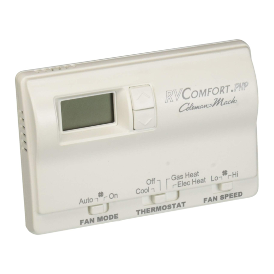
The thermostat connects to the heat pump with a 9 pin plug In electric heat mode, if the heat pump is unable to satisfy the through a lifeline (RVP part number 6795C4351). The OEM thermostat, the heat pump goes into lockout. DIFF will display... - Page 4 WIRING THE WALL THERMOSTAT OEM must supply these mating parts to connect these thermostats per Figure 1. The plugs must be connected to motorcoach wiring harness before the base if secured to the wall. Heat Pump Example To Bring On Gas Furnace As Backup Heat Setpoint Indoor Temperature Operation...
- Page 5 The chart below shows the system functions with the 6536A335* thermostat. After the entire air conditioning system (and furnace system) is installed, check each position function. 6536A335* 2-STAGE HEAT PUMP WITH BACKUP HEAT THERMOSTAT OPERATION TABLE Mode Switch Fan Mode Fan Speed Calling Operation...
-
Page 6: Heat Pump Operation Sequence Cooling Mode
II. HEAT PUMP OPERATION SEQUENCE COOLING MODE... -
Page 7: Heat Pump Operation Sequence Heating Mode
III. HEAT PUMP OPERATION SEQUENCE HEATING MODE... -
Page 8: 6535*320 Printed Circuit Board Function Chart
IV. 6535*320 PRINTED CIRCUIT BOARD FUNCTION CHART... -
Page 9: Printed Circuit Board 9-Pin Thermostat Plug Connector
PRINTED CIRCUIT BOARD 9-PIN THERMOSTAT PLUG CONNECTOR The figure above depicts the 9-pin printed circuit board socket as if you were looking straight at it. NOTE Pin connections in this p.c. board socket are identical to those in the thermostat. Low voltage connections to the p.c. -
Page 10: Printed Circuit Board Indoor Blower Section
PRINTED CIRCUIT BOARD INDOOR BLOWER SECTION Note: Both High and Low Indoor Blower speeds operate on Circuit #1 HIGH SPEED INDOOR BLOWER OPERATION Begins with a call from the thermostat, 12 volt positive (+) to terminal #7 (GH) in the 9-pin connector. (Black wire at the thermostat). -
Page 11: Printed Circuit Board Compressor Section
PRINTED CIRCUIT BOARD COMPRESSOR SECTION COMPRESSOR #1 COOLING OPERATION Begins with a call from the thermostat, 12 volt positive (+) to terminal #5 (Y1) in the 9-pin connector. (Yellow wire at the thermostat). This call is subject to thermostat time delays. The Ground (12 VDC-) is Blue in terminal #4. 12 VDC passes through the circuit board to terminals T3B and T2, Comp 1 Coil. -
Page 12: Printed Circuit Board Freeze Sensor Section
PRINTED CIRCUIT BOARD FREEZE SENSOR SECTION INDOOR COIL SENSOR The Indoor Coil Sensor, T14 and T15 terminals are connected to a thermister located in the evaporator (Indoor) coil. This sensor is an active part of the circuit only in the cooling mode. This sensor is ignored if “W”... -
Page 13: Printed Circuit Board Outdoor Blower Section
PRINTED CIRCUIT BOARD OUTDOOR BLOWER SECTION Note: These two sections of the p.c. board control both 115 volt (HOT and NEUTRAL) power legs to the OUTDOOR BLOWER. LOW SPEED OUTDOOR BLOWER OPERATION Begins with a 115 volt (HOT leg) signal received from the #1 Compressor Relay to the Comp 1 Contact In, T4 terminal on the p.c. -
Page 14: Printed Circuit Board Heating (Heat Pump) Section
PRINTED CIRCUIT BOARD HEATING SECTION HEAT PUMP OPERATION (HEAT MODE) Begins with a call from the thermostat, 12 volt positive (+) to terminal #8 (W) in the 9-pin connector. (White with Black stripe wire at the thermostat). The Ground (-) is Blue in terminal #4. The p.c. -
Page 15: Wiring Diagram - 6536 Series Two Ton Packaged Heat Pump
V. WIRING DIAGRAM - 6536 SERIES TWO TON PACKAGED HEAT PUMP... -
Page 16: Wiring Diagram - 6536 "A", 6536 "B" Series Two Ton Packaged Heat Pump
6536 “A” Model Secondary Wiring Diagram 6536 “B” SERIES TWO TON PACKAGED HEAT PUMP...
Need help?
Do you have a question about the 6536A335 Series and is the answer not in the manual?
Questions and answers