
Related Manuals for CareCo Fenix


Summary of Contents for CareCo Fenix
- Page 1 U S E R M A N U A L PRO D U CT CO D ES W C 0 9 08 4 | WC0 9 08 5 Careco UK Limited , Hubert Road, Brentwood, Essex, CM14 4JE...
-
Page 2: Table Of Contents
CONTENTS 1. PREFACE 2. SAFETY NOTICES 3. PARTS 4. ASSEMBLY & DISASSEMBLY 5. COMFORT ADJUSTMENT 6. OPERATION 7. CHARGER 8. INSPECTION & MAINTENANCE 9. TROUBLE SHOOTING 10. SPECIFICATION 11. WARRANTY... -
Page 3: Preface
1. PREFACE Please read this user manual before using your Fenix Powerchair. Improper use of the power wheelchair could result in harm, injury or traffic accidents. This user manual includes operation instructions for every aspect of the power wheelchair, assembly instructions, as well as a troubleshooting guide. -
Page 4: Safety Notices
11. The product functions best at temperature between 0*C – 50*C (32*F – 122*F). 12. Disassembling of controller, motor or charger by the end user is prohibited; CareCo will not take any responsibility in these situations. 13. Prevent the controller, charger and battery from getting wet; this can cause a malfunction. -
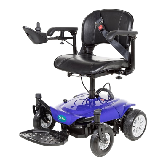
Page 5: Parts
3. PARTS 1. Backrest 7. Front Caster 13. Manual Freewheel Lever 2. Armrest 8. Footplate 14. Seat Belt 3. Joystick 9. Carry Handle 15. Frame Lock/Release 4. Controller 10. Rear Cover Lever 5. Seat 11. Rear Drive Wheel 6. Front Cover 12. -
Page 6: Assembly & Disassembly
4. ASSEMBLY & DISASSEMBLY 1. Connect the front and rear frame by matching the semicircular pegs with the frame. When correctly positioned a ‘click’ will sound from the frame lock/release lever. 2. Remove the front cover by unscrewing the 2 bolts. Place battery pack on the front frame. - Page 7 4. ASSEMBLY & DISASSEMBLY 3. Re-place the front cover on the frame. Fasten the 2 bolts on the cover. 4. Insert the seat into the seat post and secure using the nut and bolt. Then place the seat down on the wheelchair’s seat post. Now, attach the seat belt through the armrest of the chair and secure.
-
Page 8: Comfort Adjustment
5. COMFORT ADJUSTMENT 1. The seat can be rotated left or right to help the user get on and off more conveniently, by lifting up the handle on the right side of the seat. 2. The position of the controller can be adjusted forward or backward by loosening the bolt located under the armrest. - Page 9 5. COMFORT ADJUSTMENT 4. The height of the seat can be adjusted to 4 positions. 5. OPERATION GENERAL INFORMATION 1. Make sure that the motor levers are in engaged mode (parallel to the wheels.) 2. Once seated on the power wheelchair, turn on the power (press the power button). The battery gauge will turn on.
-
Page 10: Operation
6. OPERATION CONTROLLER Battery Indicator Power On/Off Horn Speed Down Button Speed Up Button Joystick BATTERY INDICATOR When the power wheelchair is turned on, the battery gauge will light up as indicated below: Green lights: the battery has full capacity. Yellow lights: do not drive power wheelchair for a long trip. -
Page 11: Charger
7. CHARGER SPECIFICATION Input Current 2A dc+5% Output Voltage 24.0Vdc+2% Input Voltage 95-250Vac Output Detection 1. Short Circuit Detection 2. Output Voltage /Current Limit 3. Reverse Power Protected Operating temperature 0°~40°C Weight 365g approx. INSTRUCTIONS 1. Connect the charger to the controller (figure I). Then connect the power lead (figure II) into the battery charger. -
Page 12: Inspection & Maintenance
7. CHARGER Warning 1. Ensure the output – DC voltage corresponds to the battery type and voltage. Otherwise it may cause damage to the charger/battery. 2. Switch off the charger before connecting e charger and the battery. 3. Do not expose the charger to rain, water or flammable materials. 4. -
Page 13: Trouble Shooting
9. TROUBLE SHOOTING If a system fault occurs, the battery gauge LED’s will start to flash. Count the number of LED’s and refer to the table below. If the problem persists after you made the checks described above, contact your dealer. Error code Possible Cause Solution... -
Page 14: Specification
10. SPECIFICATION MODEL FENIX FENIX PLUS Max Weight Capacity 250lbs/115kg 250lbs/115kg Speed 4mph 4mph Estimated Range 15 km 20 km Maximum Grade / Incline 6” 6” Turning Radius 23.6” 23.6” Ground Clearance 40mm 40mm Overal Length 895 mm 895 mm... -
Page 15: Warranty
11. WARRANTY Warranty starts from cargo arrival date, two years comprehensive warranty, but battery/wheel/consumables with half year warranty. Consumables parts include: Motor carton brush Front/rear shroud Battery fabric bag Woven band accessories Seat belt Seat cover PA GE 13... - Page 16 NOTES P A G E 1 4...
- Page 17 NOTES PA GE 15...
Need help?
Do you have a question about the Fenix and is the answer not in the manual?
Questions and answers