
Related Manuals for Roth CM Manifold


Summary of Contents for Roth CM Manifold
- Page 1 Roth CM Manifold System Installation Instructions Roth Roth Roth Industries, Inc. 268 Bellew Avenue South Watertown, NY 13601 Ph. 315-755-1011 Fax 315-475-0200 www.roth-usa.com info@roth-usa.com...
-
Page 2: Product Description
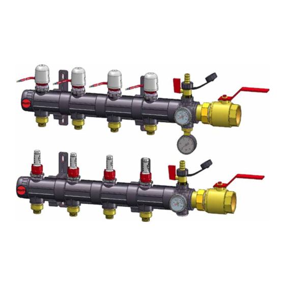
Roth CM Manifold System Installation Instructions Product Description The Roth CM Manifold System is comprised of modular large bore manifolds constructed from glass-fibre reinforced polyamide. Each manifold system includes: • Supply and return ball valves - 1 1/2” FPT • Manifold basic kit including: •... -
Page 3: Specifications
Roth CM Manifold System Installation Instructions Dimensions # - Number of loops 3.0” A - Length of segments Maximum Depth** - 7.63” max. 15” max. 8” 3.5” Depth* - 4.75” 1.5” 10.0 12.5 15.5 1.5” 18.1 21.0 23.5 2.36” 26.5 >6.75”... - Page 4 Roth CM Manifold System Installation Instructions Assembly Manifold trunk segments 1. Manifold trunk segments have a male and female threaded end. They are connected by turning clockwise until they hit the end stop. Segments will automatically line up. 2. The male end includes an o-ring. Be sure the o-ring is seated properly.
- Page 5 Roth CM Manifold System Installation Instructions Mounting Location guidelines 1. The manifold system must be accessible for future inspection and maintenance. 2. The supply/return and loop tubing should have an unobstructed approach and any bend radius must be large enough to prevent kinks.
- Page 6 Snap Orientation The CM manifold can be mounted in any position, however the following conditions may occur when manifolds are mounted in positions other than upright (loop tubing approaching from bottom): 1. Upside down position (loop tubing approaching from above) a.
-
Page 7: Pipe Connections
Caution: Alu-Laser Plus tubing must be reamed with Roth Alu-Laser Plus reaming tool. This puts a bevel on the inside of the pipe and allows the fitting to be inserted into the pipe without disturbing the o-rings on the fitting. - Page 8 Roth CM Manifold System Installation Instructions Attaching 3/4” tubing to manifold • Insert euroconical end of fitting (1) into manifold until o-ring is seated • Thread and tighten threaded adaptor (2) onto manifold • Place compression nut (4) onto tubing •...
- Page 9 Roth CM Manifold System Installation Instructions • Purge first loop with 40 - 70 psi to remove trapped air in loop • Allow water to circulate until no air is discharged into the bucket • Close supply and return valves on the first loop •...
- Page 10 Once the flow rate is set, turn stop ring clockwise until the stop engages the stop on the flowmeter • Push the stop ring down to lock CM Manifold Pressure Drop Graph CM Manifold Pressure Drop Graph Pressure Drop 65.00 14.5...
Need help?
Do you have a question about the CM Manifold and is the answer not in the manual?
Questions and answers