MR VACUTAP VR Operating Instructions Manual
On-load tap-changer
Hide thumbs
Also See for VACUTAP VR:
- Installation and commissioning instructions (268 pages) ,
- Operating instructions manual (94 pages)

Related Manuals for MR VACUTAP VR


Summary of Contents for MR VACUTAP VR
- Page 1 On-Load Tap-Changer ® ® VACUTAP Operating Instructions 6028618/00 EN . High-temperature version...
- Page 2 © All rights reserved by Maschinenfabrik Reinhausen Dissemination and reproduction of this document and use and disclosure of its content are strictly prohibited unless expressly permitted. Infringements will result in liability for compensation. All rights reserved in the event of the granting of patents, utility models or designs.
-
Page 3: Table Of Contents
Table of contents Table of contents Introduction......................... 5 Manufacturer............................ 5 Completeness............................. 5 Safekeeping............................ 5 Notation conventions .......................... 5 1.4.1 Hazard communication system .......................... 6 1.4.2 Information system.............................. 7 1.4.3 Instruction system .............................. 7 Safety........................... 9 Appropriate use .......................... 9 Inappropriate use.......................... 10 Fundamental safety instructions ....................... 10 Personnel qualification........................ - Page 4 Table of contents Fault elimination ....................... 38 Tripping the protective relay and re-commissioning the transformer.......... 41 5.1.1 Flap valve in OPERATION position ........................ 41 5.1.2 Flap valve in OFF position .......................... 42 5.1.3 Re-commissioning the transformer ........................ 42 Maintenance........................ 43 Inspection ............................ 44 Maintenance intervals........................
-
Page 5: Introduction
1 Introduction 1 Introduction This technical file contains detailed descriptions for monitoring during opera- tion, fault elimination, and maintenance. It also includes safety instructions and general information about the prod- uct. Information about installation can be found in the installation and commis- sioning instructions. -
Page 6: Hazard Communication System
1 Introduction 1.4.1 Hazard communication system Warnings in this technical file are displayed as follows. 1.4.1.1 Warning relating to section Warnings relating to sections refer to entire chapters or sections, sub-sec- tions or several paragraphs within this technical file. Warnings relating to sections use the following format: Type of danger! WARNING... -
Page 7: Information System
1 Introduction Pictograms warn of dangers: Pictogram Definition Warning of a danger point Warning of dangerous electrical voltage Warning of combustible substances Warning of danger of tipping Warning of danger of crushing Table 2: Pictograms used in warning notices 1.4.2 Information system Information is designed to simplify and improve understanding of particular procedures. - Page 8 1 Introduction Aim of action ü Requirements (optional). ► Step 1 of 1. ð Result of step (optional). ð Result of action (optional). Multi-step instructions Instructions which consist of several process steps are structured as follows: Aim of action ü Requirements (optional). 1.
-
Page 9: Safety
2 Safety 2 Safety This technical file contains detailed descriptions on the safe and proper in- stallation, connection, commissioning and monitoring of the product. ▪ Read this technical file through carefully to familiarize yourself with the product. ▪ This technical file is a part of the product. ▪... -
Page 10: Inappropriate Use
2 Safety ▪ Only use the equipment and special tools included in delivery for the in- tended purpose and in accordance with the specifications of this technical file. ▪ The on-load tap-changer is not intended to be used with an oil filter unit. Permitted electrical operating conditions In addition to the design data in accordance with the order confirmation, ob- serve the following limits for the through-current and the step voltage:... - Page 11 2 Safety Personal protective equipment Loosely worn or unsuitable clothing increases the danger of becoming trapped or caught up in rotating parts and the danger of getting caught on protruding parts. This increases the danger to life and limb. ▪ All necessary devices and personal protective equipment required for the specific task, such as a hard hat, safety footwear, etc.
-
Page 12: Personnel Qualification
2 Safety Safety markings Warning signs and safety information plates are safety markings on the product. They are an important aspect of the safety concept. ▪ Observe all safety markings on the product. ▪ Make sure all safety markings on the product remain intact and legible. ▪... -
Page 13: Personal Protective Equipment
2 Safety Electrically skilled person The electrically skilled person has a technical qualification and therefore has the required knowledge and experience, and is also conversant with the ap- plicable standards and regulations. The electrically skilled person is also pro- ficient in the following: ▪... - Page 14 2 Safety Personal protective equipment to be worn at all times Protective clothing Close-fitting work clothing with a low tearing strength, with tight sleeves and with no protrud- ing parts. It mainly serves to protect the wearer against being caught by moving machine parts. Safety shoes To protect against falling heavy objects and slip- ping on slippery surfaces.
-
Page 15: Product Description
3 Product description 3 Product description This chapter contains an overview of the design and function of the product. 3.1 On-load tap-changer 3.1.1 Function description On-load tap-changers are used to adjust the transmission ratio of transform- ers without interrupting the load flow. Fluctuations in voltage occurring in the power transmission grid, for example, can therefore be compensated for. - Page 16 3 Product description A motor-drive unit which receives a control impulse (e.g. from a voltage reg- ulator) changes the operating position of the on-load tap-changer, as a result of which the transformer's transmission ratio is adapted to the prevailing op- erating requirements.
-
Page 17: Design/Versions
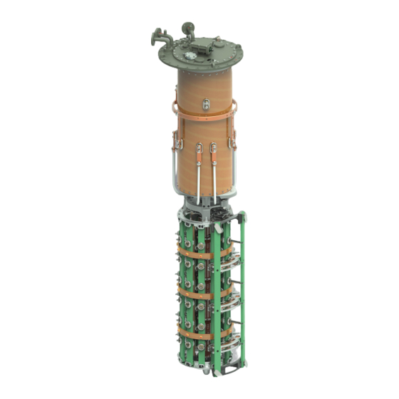
3 Product description 13 Bevel gear 14 Horizontal drive shaft 15 Upper gear unit 16 RS protective relay 3.1.2 Design/versions The on-load tap-changer consists of the on-load tap-changer head, oil com- partment with built-in diverter switch insert and the selector mounted below (also available with change-over selector on request). - Page 18 3 Product description For the number of maximum operating positions of the on-load tap-changer, refer to the technical data. Figure 2: Design of VACUTAP® VR 1 On-load tap-changer head 2 Temperature sensor 3 Pipe bend 4 Oil compartment 5 Tap selector 6 Change-over selector (optional) 7 On-load tap-changer head cover 8 Rupture disk...
- Page 19 3 Product description 3.1.2.1 Pipe connections There are 5 pipe connections on the on-load tap-changer head and on-load tap-changer head cover for various purposes. Depending on the order, some or all of these pipe connections are fitted with pipe bends ex factory. All pipe bends without terminal box for the tap-change supervisory device can be freely swiveled once the pressure ring is loosened.
-
Page 20: Nameplate And Serial Number
3 Product description Pipe connection E2 Pipe connection E2 is sealed off with a blank cover. It leads into the oil tank of the transformer, directly under the on-load tap-changer head and can be connected to a collective pipe for the Buchholz relay, if necessary. This pipe connection serves a further purpose, namely to equalize the pressure be- tween the transformer tank and oil compartment of the on-load tap-changer, which is necessary for drying, oil filling and transportation of the transformer. -
Page 21: Protective Devices
3 Product description The serial number can also be found on the selector. Figure 5: Serial number 3.1.4 Protective devices The following protective devices for the product are included as standard in the scope of delivery or are available as options. 3.1.4.1 Protective relay 3.1.4.1.1 Function description The protective relay is looped into the circuit breaker tripping circuit, thus... - Page 22 3 Product description The protective relay responds to flow, not to gas accumulated in the protec- tive relay. It is not necessary to bleed the protective relay when filling the transformer with insulating fluid. Gas accumulation in the protective relay is normal.
- Page 23 3 Product description View from above Figure 8: Protective relay RS 2001/T 1 Gasket 2 Potential tie-in 3 Terminal box cover 4 Slotted head screw for potential tie-in 5 OPERATION (reset) test button 6 Slotted head screw for protective cover 7 OFF (test tripping) test button 8 Cable gland 9 Protective cover 10 Dummy plug...
- Page 24 3 Product description 3.1.4.1.4 Safety markings The following safety markings in accordance with DIN EN 60255-27 are used on the product: Figure 10: Overview of safety markings 1 Protective conductor connection 2 Notice, danger of electric shock 3 Notice, observe the documentation 3.1.4.2 Rupture disk The rupture disk is a pressure relief device without signaling contact in ac- cordance with IEC 60214-1 and is located in the on-load tap-changer head...
-
Page 25: Drive Shaft
3 Product description 3.2 Drive shaft 3.2.1 Function description The drive shaft is the mechanical connection between motor-drive and on- load tap-changer head / de-energized tap-changer head. The bevel gear changes the direction from vertical to horizontal. Accordingly, the vertical drive shaft has to be mounted between drive and bevel gear, and the horizontal drive shaft between bevel gear and on-load tap-changer or de-energized tap-changer. -
Page 26: Design/Versions
3 Product description 3.2.2 Design/versions The drive shaft consists of a square tube and is coupled at each end by two coupling brackets and one coupling bolt to the driving or driven shaft end of the device to be connected. Figure 11: Components of the drive shaft 1 Bevel gear 2 Hose clip... - Page 27 3 Product description 3.2.2.1 Drive shaft without cardan joint and without insulator Figure 12: Drive shaft without cardan joint and without insulator (= standard version) Configuration V 1 min Intermediate bearing Middle of hand crank – middle of 536 mm When the maximum value bevel gear (maximum permissible of 2472 mm is exceeded, it axial offset 2°)
- Page 28 3 Product description 3.2.2.2 Drive shaft without cardan joint and with insulator Figure 13: Drive shaft without cardan joint and with insulator (= special model) Configuration V 1 min Intermediate bearing Middle of hand crank – middle of 706 mm When the maximum value bevel gear (maximum permissible of 2472 mm is exceeded, it axial offset 2°)
- Page 29 3 Product description Figure 14: Drive shaft with cardan joints, without insulator (= special model) Configuration V 1 min [mm] Intermediate bearing for [mm] Middle of hand crank – middle of V 1 > 2564 bevel gear 3.2.2.4 Drive shaft with cardan joint and with insulator An axial displacement of maximum 20°...
- Page 30 3 Product description Figure 15: Drive shaft with cardan joint and with insulator (= special model) Configuration V 1 min [mm] Intermediate bearing for [mm] Middle of hand crank – middle of V 1 > 2772 bevel gear ® ® VACUTAP 6028618/00 EN Maschinenfabrik Reinhausen GmbH 2018...
-
Page 31: Identification Plate
3 Product description 3.2.3 Identification plate The identification plate is on the telescopic protective tube. Figure 16: Position of the identification plate ® ® Maschinenfabrik Reinhausen GmbH 2018 6028618/00 EN VACUTAP... -
Page 32: Commissioning
4 Commissioning 4 Commissioning WARNING Danger of explosion! Explosive gases in the oil compartment of the on-load tap-changer, trans- former, pipework system, oil conservator and at the dehydrating breather opening can deflagrate or explode and result in severe injury or death! ►... - Page 33 4 Commissioning 2. Establish a connecting lead between pipe connection E2 and one of the pipe connections R, S or Q to ensure equal pressure in the oil compart- ment and transformer during evacuation. Figure 17: Connecting lead between E2 and Q 3.
-
Page 34: Bleeding On-Load Tap-Changer Head And Pipe System
4 Commissioning 4.1.2 Bleeding on-load tap-changer head and pipe system Prior to commissioning, you must bleed the on-load tap-changer head and the pipe system. 4.1.2.1 Bleeding on-load tap-changer head 1. Open all forward valves and return valves in the pipe system. 2. -
Page 35: Checking Motor-Drive Unit
4 Commissioning 4.1.2.2 Bleeding the pipe system 1. Remove the screw caps on the pipe bends on pipe connections A and S. Figure 21: Screw cap 2. Open the vent screw and bleed the pipe system. 3. Close the vent screw and seal with the screw caps. 4. -
Page 36: Checking Protective Relay (Rs 2001, 2001/V, 2001/H, 2001/E, 2001/5, 2001/R, 2001/T, 2003)
Tests on the motor-drive unit 1. Perform function checks as described in relevant MR operating instruc- tions for motor-drive unit. NOTICE! An incorrectly coupled motor-drive unit will lead to damage to the on-load tap-changer. -
Page 37: Commissioning The Transformer
4 Commissioning 5. Remove the slotted head screw for potential tie-in and remove the termi- nal box cover with wire. 6. Press OFF test button. 7. Leave the transformer's danger zone. 8. Ensure that the transformer's circuit breaker cannot be closed. ð... -
Page 38: Fault Elimination
In the event of faults on the on-load tap-changer or motor-drive unit which cannot be easily corrected on site, or if the RS protective relay or additional protective devices have been tripped, please inform your authorized MR rep- resentative, the transformer manufacturer or contact us directly at:... - Page 39 Contact MR in the event of noise from the motor-drive unit. Red message on monitoring unit If possible read out database and send to MR along with error code. Warning or tripping of Buchholz relay on transformer Notify manufacturer of transformer.
- Page 40 On-load tap-changer switches to static operation and mes- ▪ Check fan and eliminate fault sage "OLTC Oil Temperature >120°C" (K44) and oil cool- ▪ If the fan is OK: Contact MR ing pump runs (K7/Q4) ▪ Reduce temperature of the insulating fluid in the oil compartment to <120°C* until fault elimination...
-
Page 41: Tripping The Protective Relay And Re-Commissioning The Transformer
5 Fault elimination *Due to the insulating effect of the oil compartment, the transformer temper- ature is approximately 10°C higher than the oil compartment interior temper- ature 5.1 Tripping the protective relay and re-commissioning the transformer WARNING Danger of explosion! Explosive gases in the protective relay can deflagrate or explode and result in severe injury or death. -
Page 42: Flap Valve In Off Position
5 Fault elimination 5.1.2 Flap valve in OFF position If the flap valve is in the OFF position, proceed as follows: 1. Ensure that the transformer is not started up under any circumstances. 2. Contact and inform Maschinenfabrik Reinhausen of the following: ð... -
Page 43: Maintenance
6 Maintenance 6 Maintenance DANGER Electric shock! Working on the transformer when the transformer is energized can lead to death or serious injuries. ► Switch off transformer on high and low-voltage side. ► Lock transformer to prevent unintentional restart. ► Ensure that everything is de-energized. ►... -
Page 44: Inspection
"Changing the insu- lating fluid". Table 4: Inspection plan 6.2 Maintenance intervals Maintenance intervals without MR monitoring system Danger of explosion! WARNING If pending maintenance work is not carried out immediately, this may lead to death or serious injury as a result of a progressive short circuit, for example. - Page 45 6 Maintenance If you are operating the on-load tap-changer without an MR monitoring sys- tem, the following maintenance intervals shall apply. Interval Action After every 100,000 switching operations Replace on-load tap-changer. Contact (motor-drive unit counter reading) the Maschinenfabrik Reinhausen GmbH Technical Service for this.
-
Page 46: Changing The Insulation Fluid
MR monitoring system issues a maintenance warning. ► In the event of failure or shutdown of the MR monitoring system, observe the maintenance intervals as specified in the maintenance plan without the MR monitoring system. - Page 47 6 Maintenance 1. Loosen hose clips on protective cover of horizontal drive shaft, remove protective cover. Figure 23: Removing protective cover ® ® Maschinenfabrik Reinhausen GmbH 2018 6028618/00 EN VACUTAP...
-
Page 48: Emptying The Oil Compartment And Oil Conservator
6 Maintenance 2. Depending on version, loosen 4 or 6 screws on coupling brackets to upper gear unit and bevel gear. Figure 24: Loosening coupling brackets 3. Remove horizontal drive shaft. Be sure not to lose the coupling bolts. Figure 25: Removing drive shaft 6.3.3 Emptying the oil compartment and oil conservator 1. -
Page 49: Filling The Oil Compartment And Oil Conservator With Fresh Insulating Fluid
6 Maintenance 4. Once the gas has been discharged and insulating fluid is flowing out of the air-vent valve, close the air-vent valve. 5. Close the stop-cock between the oil conservator and on-load tap-changer. 6. Open the air-vent valve E1 again and drain off the insulating fluid until the area under the on-load tap-changer head cover is unoccupied. - Page 50 6 Maintenance 2. Insert the new o-ring untwisted in the on-load tap-changer head cover. 3. Position the on-load tap-changer head cover on the on-load tap-changer head in such a way that the red triangular markings on the on-load tap- changer head and the on-load tap-changer head cover are aligned. Figure 28: Triangular markings and o-ring 4.
- Page 51 6 Maintenance 8. Remove screw cap from pipe connection S. Figure 30: Pipe connection S 9. Open vent screw and bleed pipe system. 10. Close vent screw. 11. Seal vent screw with screw cap. 12. Check the level in the oil conservator and top up with insulating fluid if necessary.
-
Page 52: Installing Horizontal Drive Shaft
6 Maintenance 6.3.5 Installing horizontal drive shaft 1. Secure horizontal drive shaft between upper gear unit and bevel gear with coupling brackets and 4 or 6 screws. Refer to the drive shaft operating in- structions for details. Figure 31: Securing drive shaft ®... -
Page 53: Centering On-Load Tap-Changer And Motor-Drive Unit
3. For special design types featuring cardan shafts, be sure to check the ex- pansion bellows and the lubricant reservoir of the cardan shafts. You will find a detailed description of how to fit the drive shaft in the MR op- erating instructions "Drive shaft". -
Page 54: Technical Data
7 Technical data 7 Technical data An overview of all key technical data for the on-load tap-changer and motor- drive unit exists in the form of separate documents, which are available on request. 7.1 Technical data for on-load tap-changer 7.1.1 On-load tap-changer properties Electrical data for VACUTAP®... -
Page 55: Permissible Ambient Conditions
7 Technical data 7.1.2 Permissible ambient conditions Air temperature during operation -25…+50°C Temperature of the insulating fluid in the trans- Normal temperature range former in operation -15…+105°C: continuous Increased temperature range 105…130°C: max. 8 hours/day, max. 720 hours/year 130…150°C: max. 8 hours/day, max. 240 hours/year Temperature of the insulating fluid in the oil -15…+120°C compartment in operation... - Page 56 7 Technical data Electrical data for normally closed (NC) dry-reed magnetic switch Electrical data DC switching capacity 1.2 W…200 W AC switching capacity (50 Hz) 1.2 VA…400 VA Switching voltage AC/DC 24 V…250 V Switched current AC/DC 4.8 mA…2 A Table 10: Electrical data Switching capacity (switching load on an off) Minimum switched current AC/DC (low-...
-
Page 57: Protective Relay With Several Dry-Reed Magnetic Switches
7 Technical data Switching capacity (switching load on an off) Minimum switched current AC/DC (low- 50 mA (at 24 V) est voltage) Minimum switched current AC/DC (high- 4.8 mA (at 250 V) est voltage) Maximum switched current DC (highest 2 A (at 125 V with L/R = 40 ms) current) Maximum switched current DC (highest 1 A (at 250 V with L/R = 40 ms) -
Page 58: Tests
7 Technical data 7.2.2 Tests Electrical safety IEC 61010-1 Safety requirements for electrical measurement and con- trol and regulation equipment and laboratory instruments ▪ Overvoltage category III ▪ Contamination level 2 Table 17: Electrical safety ® ® VACUTAP 6028618/00 EN Maschinenfabrik Reinhausen GmbH 2018... -
Page 59: Limit Values For Dielectric Strength And Water Content Of On-Load Tap-Changer Oil
7.3 Limit values for dielectric strength and water content of on-load tap-changer oil 7.3 Limit values for dielectric strength and water content of on- load tap-changer oil The following table specifies the limit values for dielectric strength (measured in accordance with IEC 60156) and water content (measured in accordance with IEC60814) of the insulating fluid. -
Page 60: Drawings
8 Drawings 8 Drawings 8.1 Dimensional drawings ® ® VACUTAP 6028618/00 EN Maschinenfabrik Reinhausen GmbH 2018... - Page 61 Ra 3,2 PROTECTIVE RELAY MOUNTING FLANGE ON TRANSFORMER COVER M12 FIXING SCREW ON-LOAD TAP-CHANGER HEAD GASKET POSITION INDICATOR, REMOVE BEFORE REMOVING THE DIVERTER SWITCH INSERT INSPECTION WINDOW O 15 HOLES SUCTION PIPE ON-LOAD TAP-CHANGER HEAD COVER SCREW COVER GASKET ON-LOAD TAP-CHANGER HEAD COVER MAINTAIN SUFFICIENT DISTANCE CENTRAL GEAR UNIT WITH 25a DRIVE SHAFT PIPE CONNECTION R FOR PROTECTIVE RELAY...
- Page 62 ON-LOAD TAP-CHANGER VACUTAP® VR SERIAL NUMBER DIMENSION IN mm VR S/M - SELECTOR SIZE B/C/D/DE MATERIAL NUMBER SHEET EXCEPT AS INSTALLATION POSITION OF SELECTOR CONNECTION CONTACTS 100180450E NOTED...
- Page 63 > 75,5 M6 / WRENCH 10 MA = 7,5 Nm ASSEMBLY INTERFACE 60 H8 FREELY ROTATABLE 1: 2 MEMBRANE VENT M20 x 1,5 TECHNICAL DATA HOUSING: OUTDOOR DESIGN, POWDER COATED RAL 9006 WHITE ALUMINIUM (C5) HOUSING MATERIAL: SEAWATER RESISTANT ALUMINIUM PROTECTION TYPE: IP66 ACCORDING TO IEC 60529 (CLOSED DEVICE) AMBIENT TEMPERATURE: -40°C TO +150°C (-40°F TO +302°F) OIL TEMPERATURE: -40°C TO +150°C (-40°F TO +302°F)
-
Page 64: On-Load Tap-Changer Head
8.2 On-load tap-changer head 8.2 On-load tap-changer head ® ® VACUTAP 6028618/00 EN Maschinenfabrik Reinhausen GmbH 2018... - Page 65 43 WIDTH OF GASKET CONNECTION FLANGE FOR S, R, A 1: 1 O-RING 29-3 16 THICKNESS 37,5 E1 = BLEEDING FACILITY FOR ON-LOAD TAP-CHANGER HEAD E2 = BLEEDING FACILITY FOR SPACE UNDER THE HEAD OUTSIDE THE TAP-CHANGER OIL COMPARTMENT (SAME PIPE CONNECTION AS R, S OR BLEEDER SCREW CAN BE USED) Q = CONNECTION FOR OIL RETURN OR TAP CHANGE SUPERVISORY CONTROL S = CONNECTION FOR OIL RETURN WITH BLEEDER SCREW R = CONNECTION FOR PROTECTIVE RELAY...
-
Page 71: Adjustment Plans
8.3 Adjustment plans 8.3 Adjustment plans ® ® Maschinenfabrik Reinhausen GmbH 2018 6028618/00 EN VACUTAP... - Page 72 THE CONNECTION DIAGRAM OF THE ON-LOAD TAP-CHANGER IS BINDING ON-LOAD FOR THE DESIGNATION AND TAP-CHANGER THE EQUIPMENT OF THE TERMINALS HEAD AND PHASES. = DRIVE SIDE OF THE SELECTOR = ON-LOAD TAP-CHANGER TAKE-OFF TERMINAL DIVERTER SWITCH INSERT TOP VIEW 1 SECTOR 3 SECTORS 2 SECTORS DIVERTER SWITCH...
- Page 73 THE CONNECTION DIAGRAM OF THE ON-LOAD TAP-CHANGER IS BINDING ON-LOAD FOR THE DESIGNATION AND TAP-CHANGER THE EQUIPMENT OF THE TERMINALS HEAD AND PHASES. = DRIVE SIDE OF THE SELECTOR = ON-LOAD TAP-CHANGER TAKE-OFF TERMINAL DIVERTER SWITCH INSERT TOP VIEW 1 SECTOR 2 SECTORS 3 SECTORS DIVERTER SWITCH...
- Page 74 THE CONNECTION DIAGRAM OF THE ON-LOAD TAP-CHANGER IS BINDING FOR THE DESIGNATION AND ON-LOAD THE EQUIPMENT OF THE TERMINALS TAP-CHANGER AND PHASES. HEAD = DRIVE SIDE OF THE SELECTOR = ON-LOAD TAP-CHANGER TAKE-OFF TERMINAL DIVERTER SWITCH INSERT TOP VIEW 3 SECTORS 1 SECTOR 2 SECTORS DIVERTER SWITCH...
- Page 75 THE CONNECTION DIAGRAM OF THE ON-LOAD TAP-CHANGER IS BINDING FOR THE DESIGNATION AND ON-LOAD THE EQUIPMENT OF THE TERMINALS TAP-CHANGER AND PHASES. HEAD = DRIVE SIDE OF THE SELECTOR = ON-LOAD TAP-CHANGER TAKE-OFF TERMINAL DIVERTER SWITCH INSERT TOP VIEW 1 SECTOR DIVERTER SWITCH SELECTOR COUPLING GENEVA WHEEL LOWER...
- Page 76 THE CONNECTION DIAGRAM OF THE ON-LOAD TAP-CHANGER IS BINDING FOR THE DESIGNATION AND ON-LOAD THE EQUIPMENT OF THE TERMINALS TAP-CHANGER AND PHASES. HEAD = DRIVE SIDE OF THE SELECTOR = ON-LOAD TAP-CHANGER TAKE-OFF TERMINAL DIVERTER SWITCH INSERT TOP VIEW 2 SECTOR 3 SECTORS DIVERTER SWITCH SELECTOR COUPLING...
- Page 77 THE CONNECTION DIAGRAM OF THE ON-LOAD TAP-CHANGER IS BINDING FOR THE DESIGNATION AND ON-LOAD THE EQUIPMENT OF THE TERMINALS TAP-CHANGER AND PHASES. HEAD = DRIVE SIDE OF THE SELECTOR = ON-LOAD TAP-CHANGER TAKE-OFF TERMINAL DIVERTER SWITCH INSERT TOP VIEW 1 SECTOR 3 SECTORS DIVERTER SWITCH SELECTOR COUPLING...
- Page 78 THE CONNECTION DIAGRAM OF THE ON-LOAD TAP-CHANGER IS BINDING FOR THE DESIGNATION AND ON-LOAD THE EQUIPMENT OF THE TERMINALS TAP-CHANGER AND PHASES. HEAD = DRIVE SIDE OF THE SELECTOR = ON-LOAD TAP-CHANGER TAKE-OFF TERMINAL DIVERTER SWITCH INSERT TOP VIEW 1 SECTOR 3 SECTORS DIVERTER SWITCH SELECTOR COUPLING...
- Page 79 THE CONNECTION DIAGRAM OF THE ON-LOAD TAP-CHANGER IS BINDING FOR THE DESIGNATION AND ON-LOAD THE EQUIPMENT OF THE TERMINALS TAP-CHANGER AND PHASES. HEAD = DRIVE SIDE OF THE SELECTOR = ON-LOAD TAP-CHANGER TAKE-OFF TERMINAL DIVERTER SWITCH INSERT TOP VIEW 1 SECTOR 3 SECTORS DIVERTER SWITCH SELECTOR COUPLING...
- Page 80 THE CONNECTION DIAGRAM OF THE ON-LOAD TAP-CHANGER IS BINDING FOR THE DESIGNATION AND ON-LOAD THE EQUIPMENT OF THE TERMINALS TAP-CHANGER AND PHASES. HEAD = DRIVE SIDE OF THE SELECTOR = ON-LOAD TAP-CHANGER TAKE-OFF TERMINAL DIVERTER SWITCH INSERT TOP VIEW 1 SECTOR 3 SECTORS DIVERTER SWITCH SELECTOR COUPLING...
- Page 81 THE CONNECTION DIAGRAM OF THE ON-LOAD TAP-CHANGER IS BINDING FOR THE DESIGNATION AND ON-LOAD THE EQUIPMENT OF THE TERMINALS TAP-CHANGER AND PHASES. HEAD = DRIVE SIDE OF THE SELECTOR = ON-LOAD TAP-CHANGER TAKE-OFF TERMINAL DIVERTER SWITCH INSERT TOP VIEW 1 SECTOR 3 SECTORS DIVERTER SWITCH SELECTOR COUPLING...
-
Page 82: Glossary
Glossary Glossary Dielectric strength Material-specific property of isolators [kV/2.5 Ingress protection mm]; maximum electrical field strength without a breakdown (arc) Maschinenfabrik Reinhausen GmbH The International Electrotechnical Commission (IEC for short) is involved in the preparation and publication of international standards for electri- cal, electronic and related technologies. - Page 84 Maschinenfabrik Reinhausen GmbH Falkensteinstrasse 8 93059 Regensburg +49 (0)941 4090-0 +49(0)941 4090-7001 sales@reinhausen.com www.reinhausen.com 6028618/00 EN - VACUTAP® VR® - - 05/18 - Maschinenfabrik Reinhausen GmbH 2018 THE POWER BEHIND POWER.
Need help?
Do you have a question about the VACUTAP VR and is the answer not in the manual?
Questions and answers