Table of Contents
Advertisement
Advertisement
Table of Contents
Troubleshooting

Related Manuals for Epsolar ViewStar Series


Summary of Contents for Epsolar ViewStar Series
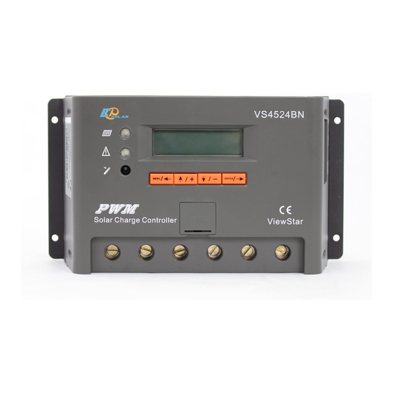
- Page 1 ViewStar series ——Solar Charge Controller User Manual Model: VS4524BN...
- Page 2 Important Safety Instructions Please keep this manual for future review. This manual contains all instructions of safety, installation and operation for VS BN series controller ("the controller" as referred to in this manual). General Safety Information Read carefully all the instructions and warnings in the manual before installation. ...
-
Page 3: Table Of Contents
CONTENTS 1. General Information ................1 1.1 Overview ..................1 1.2 Characteristics ................2 2. Installation Instructions ..............3 2.1 General Installation Notes ............3 2.2 Installation and Wiring..............3 3. HMI Interface ..................6 3.1 Button ..................6 3.2 Indicator ..................7 3.3 Operation Interface .............. -
Page 4: General Information
1. General Information 1.1 Overview ViewStar series solar charge controller adopts advanced digital control technology, LCD display and automatical operation. With the features of Pulse Width Modulation (PWM) battery charging and unique control technology, the controller will improve the long battery life efficiently. Our controller has many unique features and easy to use. -
Page 5: Characteristics
1.2 Characteristics Battery slot ❶ ❼ RS485 communication port (battery model is CR2032-3.3V) ❷ ❽ Local temperature sensor RTS★port ❸ ❾ Mounting Hole Φ4mm Fault LED indicator ❹ ❿ Charging LED indicator Load Terminals ❺ ⓫ Battery Terminals ❻ ⓬ Buttons PV Terminals ★The controller is charging and discharging at the local temperature sensor when the remote... -
Page 6: Installation Instructions
2. Installation Instructions 2.1 General Installation Notes Read through the entire installation section first before beginning installation. Be very careful when working with batteries. Wear eye protection. Have fresh water available to wash and clean any contact with battery acid. ... - Page 7 Step 1: Determination of Installation Location and Heat-dissipation Space Determination of installation location: The controller shall be installed in a place with sufficient air flow through the radiators of the controller and a minimum clearance of 150 mm from the upper and lower edges of the controller to ensure natural thermal convection.
- Page 8 WARNING: Risk of electric shock! Exercise caution when handling solar wiring. The solar module(s) high voltage output can cause severe shock or injury. Be careful operation when installing solar wiring. Step 3:Grounding VS BN series is a common-negative controller, where all the negative terminals of PV array, battery and load can be grounded simultaneously or any one of them will be grounded.
-
Page 9: Hmi Interface
3. HMI Interface 3.1 Button Button Note Menu Cursor left button Cursor up Number add button Cursor down Number reduce button Enter cursor right button... -
Page 10: Indicator
3.2 Indicator Color Status Instruction Indicator Green On Solid Charging Measure Err, MOS-I Short, MOS-C Short, MOS Break BATT: Flashing (6Hz) OVD,Over Temp LOAD: Overload,Short, MOS Short DEVICE: Over Temp Flashing BATT: Green & Red & (6Hz) Rated V Err 3.3 Operation Interface Initialization Interface When controller is powered on, the following picture will be painted during the initialization:... - Page 11 Press button to enter into main menu 2 and main menu 3 interface which displays the following contents: Monitoring Display: Solar array voltage and current→Battery voltage and current→Battery temperature and battery SOC→Load voltage and current→Real-time clock and imaging system status→System status→ Charging energy statistics→Discharging energy statistics...
- Page 12 System status icons: Icons Status Icons Status Night Charging Normal ▲ Normal ▲Icons indicating battery charging are dynamic effects. System status : System Status System Status Connect Measure Err★ Normal MOS-C Short★ Rated V Err★ BATT Disconnect MOS-I Short★ OVD★ MOS Break★...
- Page 13 Normal DEVICE MOS Short★ OverTemp★ ★When fault with inverse cursor above exists for 2 minutes along without any operation, it will jump into that page automatically. Device Set Display:Date set→ID and LCD backlight time set→TempUnit set Device parameters Parameter Detail Range:1~200 Clock...
- Page 14 Parameter Set ◆The interface will prompt only when the SOC is selected in the Batt Mng Mode. Display:Temperature compensation coefficient→Control parameters interface 1/2/3/4/5...
- Page 15 Lead-acid battery parameters The parameters are in 12V system at 25 º C, please double the values in 24V system. Battery type Sealed Flooded User Voltage Over Voltage Disconnect Voltage 9~17V 16.0V 16.0V 16.0V Charging Limit Voltage 9~17V 15.0V 15.0V 15.0V Over Voltage Reconnect Voltage...
- Page 16 Load Set Display:①Manual /②Light On/Off /③Light On+Timer /④Time Threshold voltage value Night Time Threshold Voltage: 6V/12V,12V/24V Day Time Threshold Voltage: 5V/12V,10V/24V...
- Page 17 Load working mode 1. Manual(default) Control ON/OFF of the load via the button or remote commands. 2.Light ON/OFF 3.Light ON+Timer 4.Time Control the load ON/OFF time through setting the real-time clock. NOTE: In the mode of Light ON/OFF and Light ON/Timer, the Load is turned on after 10Min.
- Page 18 Rated Value ▼ System Nominal Voltage and Battery Rate Setting System nominal voltage Battery capacity range Batt Range :0~9999AH 12V/24V/Auto Battery Type Battery Type Note Constant value▲ Sealed (default) Constant value▲ Constant value▲ Flooded Defined by user▲ User ▲The parameters refer to the Lead-acid battery parameters (Parameter Set). Test Mode ,choose the Test Mode,then press Press...
- Page 19 Password Batt Mng Mode SOC parameters Precent of charging 100% constant value 10~80%, Low SOC reconnect is higher Low SOC Precent of discharging disconnect than 5%...
- Page 20 Factory Reset Reboot Device...
-
Page 21: Accessories (Optional)
4. Accessories (optional) Acquisition of battery temperature for undertaking temperature compensation of control parameters, the standard length of the cable is 3m (length can be customized). The Remote Temperature Sensor RTS300R47K3.81A connects to the port (8 ) on the controller. (RTS300R47K3.81A) NOTE: The temperature sensor short-circuited or damaged, the controller will be charging or discharging at the default temperature 25 º... - Page 22 WARNING: Do not use the standard twisted-net cable to connect the device and PC net interface, or the permanent damage will occur.
-
Page 23: Protections, Troubleshooting And Maintenance
5. Protections, Troubleshooting and Maintenance 5.1 Protection When not in PV charging state, the controller will not be damaged in case of a short-circuiting in the PV PV Short Circuit array. When the polarity of the PV array is reversed, the controller may not be damaged and can continue to PV Reverse Polarity operate normally after the polarity is corrected. -
Page 24: Troubleshooting
5.2 Troubleshooting Faults Possible reasons Troubleshooting Charging LED indicator is off during Check that PV and battery wire connections are correct and daytime and the monitor shows PV Array Disconnection tight. Disconnect. Monitor interface PV shows Measure Please restart controller; Err, MOS-I Short, MOS-C Short, MOS MOS-I Or MOS-C Damage if the fault still exists, switch off controller immediately and... -
Page 25: Maintenance
and the LOAD of monitoring interface Damage and discharging circuit immediately and contact the supplier to shows MOS-I Short,Error. make maintenance. Fault indicator flashing Charging and discharging circuit is off When the temperature of controller exceeds 85℃, the and the LOAD monitor shows Over controller will cut input and output circuit. -
Page 26: Technical Specifications
6. Technical Specifications Item VS4524BN 12∕24VDC Auto System nominal voltage Battery voltage range 9V ~32V Max. PV open circuit voltage Rated charge current Rated discharge current ≤0.69V Charge circuit voltage drop ≤0.17V Discharge circuit voltage drop Battery type Sealed / Gel / Flooded / User -3mV∕℃∕2V(25℃)... -
Page 27: Annex Mechanical Dimension Diagram
Annex Mechanical Dimension Diagram VS4524BN(Unit:mm) Any changes without prior notice! Version number: 1.0... - Page 28 BEIJING EPSOLAR TECHNOLOGY CO., LTD. Tel: +86-10-82894112 / 82894962 Fax: +86-10-82894882 E-mail:info@epsolarpv.com Website: http://www.epsolarpv.com/ http://www.epever.com/...
Need help?
Do you have a question about the ViewStar Series and is the answer not in the manual?
Questions and answers