
Related Manuals for Henkelman Jumbo


Summary of Contents for Henkelman Jumbo
- Page 1 Vacuum Packaging Machine Jumbo Service Agent Manual Original Instructions for Use © Henkelman 2016...
- Page 2 For information about settings, maintenance and repairs not provided for in this service agent manual, please contact the technical department of your supplier. Henkelman BV / Henkelman Inc. accepts no liability for damage and/or problems arising from the use of spare parts not supplied by Henkelman BV / Henkelman Inc..
-
Page 3: Table Of Contents
Contents List of Figures..........................6 1 Preamble............................7 2 Safety.............................8 2.1 List of the Symbols Used in this Manual................8 2.2 Pictograms on the Machine....................8 2.3 General Warnings........................9 2.4 Warnings During Use......................10 2.5 Warnings for Operating Personnel..................10 3 Introduction..........................11 4 Description of the Machine.......................12 4.1 Overview of the Main Components..................12... - Page 4 10.4.1.1 Starting the Machine (Machine Is Switched On)..........61 10.4.1.2 Vacuum....................... 64 10.4.1.3 Seal........................70 10.4.1.4 Decompression....................73 10.4.1.5 General Problems....................74 10.4.2 Jumbo Call Script (Other Than Mini Jumbo)..............75 10.4.2.1 Starting the Machine (Machine Is Switched On)..........75 10.4.2.2 Vacuum....................... 78 10.4.2.3 Seal........................85 10.4.2.4 Decompression....................89...
- Page 5 10.4.2.5 General Problems....................90 10.5 Logbook..........................91 10.6 EC Declaration of Conformity.................... 93 Contents...
-
Page 6: List Of Figures
List of Figures Figure 1: Overview of the Main Components................. 12 Figure 2: Opening Front Panel......................13 Figure 3: Overview of the Sealing System..................15 Figure 4: Overview of the Pump (5 m3 / 169 cf)................16 Figure 5: Overview of the Pump (9 m3 / 338 cf)................16 Figure 6: Overview of the Pump (19 m3 / 678 cf)................17 Figure 7: Overview of the Electrical Installation................18 Figure 8: Control Panel of the 1-Program Control................ -
Page 7: Preamble
Preamble This is the manual for your Henkelman vacuum packaging machine. This manual is intended for anyone who works with or services the machine. This manual contains information and instructions for installation, operation and maintenance of the machine. We recommend that you carefully read this manual before use and follow the procedures and instructions strictly. -
Page 8: Safety
Safety Your vacuum packaging machine has been carefully designed and expertly built to be operated safely. This is corroborated by the EC Declaration of Conformity. However, there are always dangers and safety risks that cannot be eliminated. These dangers and risks are the result of the use functions of the machine and operation of the machine by the user. -
Page 9: General Warnings
Caution sign ‘Hot surface’ • Is located on the housing of the machine Machine plate • Is located on the back of the machine Regularly check whether the pictograms and markings are still clearly recognisable and legible. Replace them if this is not the case. General Warnings •... -
Page 10: Warnings During Use
• If work must be carried out on the machine, it must be disconnected and blocked from the power supply. • Only a technical expert may perform work on the electrical installation. • Internal procedures and monitoring must be in place to ensure that all relevant power supplies are disconnected. -
Page 11: Introduction
Introduction Henkelman is a supplier of ultra-modern vacuum packaging machines. Our machines are developed and manufactured to meet the highest standards. They combine a sleekly built and functional design with optimal ease of use and a long service life. After mounting the plug, it is just a matter of ‘plug &... -
Page 12: Description Of The Machine
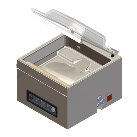
Description of the Machine This section provides an overview of the main components and functions. If detailed information is available in this manual, you will be referred to the specific sections. Overview of the Main Components The figure below shows the main components of the system. The model shown may differ from your machine. -
Page 13: Removing Front Panel
Vacuum pump The vacuum pump creates the vacuum. Power connection and cable This serves to connect the machine to the power supply. Circuit breaker The circuit breaker protects against overload or short circuit. Removing Front Panel With every machine two special tools are delivered to remove the front panel. To remove the front panel: Put the tools into the slots at the bottom of the front panel. -
Page 14: General Functions
Step Process phase Operation Preparation The operator puts the product in a vacuum bag and places it on the work surface with the opening on the sealing position. Applying vacuum The vacuum process is initiated by closing the lid. During the cycle, the air will be removed from the chamber until the set time has been reached. -
Page 15: Sealing System
Sealing System The sealing system closes the opening(s) of the bag to retain the vacuum and/or gas in the bag. The end of the bag can optionally be cut off by the sealing bar. Figure 3: Overview of the Sealing System Sealing bar The sealing bar consists of the following components: •... -
Page 16: Vacuum Pump
Vacuum Pump The vacuum pump creates the vacuum. Figure 4: Overview of the Pump (5 m / 169 cf) Figure 5: Overview of the Pump (9 m / 338 cf) Description of the Machine... -
Page 17: Electrical Installation
Figure 6: Overview of the Pump (19 m / 678 cf) Vacuum pump - Creates the vacuum for the process. Oil exhaust filter - Filters the air by capturing oil vapours. Oil sight glass - Indicates the maximum and minimum oil levels of the vacuum pump. Oil drain plug - Removing the oil drain plug allows the oil to be drained. -
Page 18: Figure 7: Overview Of The Electrical Installation
Figure 7: Overview of the Electrical Installation Power connection and cable This serves to connect the machine to the power supply. Control panel This serves to operate the control functions. Your machine has the following control option: • Operating Elements of the 1-Program Control on page 21 Circuit breaker Protection against overload or short circuit. -
Page 19: Installation
Installation Consult Technical Data on page 42 for the specifications of the machine. Before installing the machine, carefully read the safety instructions in Safety on page 8. Failure to follow or disregard of the safety instructions may result in serious injury. Transportation and Installation The machine must be moved and transported in an upright position. -
Page 20: Start-Up Codes
Start-up Codes Display code Service hours Additional External vacuum counter service indicator Installation... -
Page 21: Operation
Operation It is possible to optimise a program for your products by modifying the parameters of a program, see Changing the Program Settings on page 23. • All persons responsible for the operation of this machine must at least fully read and understand the chapters Safety on page 8 and Operation on page 21. -
Page 22: Starting The Machine
– / STOP button This is used to interrupt the entire cycle during a packaging cycle. All functions are skipped and the cycle is terminated. In the programming mode, the value of the selected parameter can be lowered using this button. + / VACUUM STOP button This stops the active function and proceeds to the next program step. -
Page 23: Changing The Program Settings
Terminate the program. Press the – / STOP button. The program will be terminated and the vacuum chamber is decompressed. Changing the Program Settings 6.6.1 1-Program Control System This section describes the units and limits of the parameters and how parameters can be adjusted. See Operating Elements of the 1-Program Control on page 21 for an overview of the operating elements of the 1-program control system. -
Page 24: Figure 9: External Vacuum Adapter Set (1-Program Control)
Press and hold the + / VACUUM STOP button, – / STOP button and Cursor key and turn on the machine. After 2 seconds, will appear on the display. Release the buttons. Press the Cursor key twice. will appear on the display to indicate the external vacuum option. Press the + / VACUUM STOP button to activate the external vacuum option. -
Page 25: Guideline For Function Values
Guideline for Function Values Values can be set for each function. In order to understand the consequence of the set value, the table below explains the consequences of giving a low or high value for each function. Function Range Conditions Vacuum 2-99 seconds Rule of thumb: the higher the vacuum, the less oxygen... -
Page 26: Figure 10: Vapour Pressure Curve Of Water
Figure 10: Vapour Pressure Curve of Water Operation... -
Page 27: Maintenance
Maintenance When carrying out maintenance work, always observe the following safety rules. • Only trained technicians are authorised to perform the described maintenance activities. • Always disconnect the power supply by disconnecting the plug. • Test the machine after carrying out maintenance work or repairs to make sure the machine can be used safely. -
Page 28: Setting Service Hour Counter (1-Program Control System)
This function is optional. It is not activated in the standard factory settings. After expiration of the set time interval, the control panel will show a signal: This means that the interval has expired and maintenance needs to be carried out. The machine will still operate normally but the signal will keep coming back. -
Page 29: Cleaning The Machine
Activity * 1-D 1-W 6-M 1-Y 4-Y Cleaning Cleaning the machine. Inspections Check the oil level. Run the pump cleaning program. Inspect the sealing bars. Inspect the silicone rubber of the silicone holders. Inspect the lid gasket. Check the plastic lid for cracks. Inspect the lid springs. -
Page 30: Running The Pump Cleaning Program
Running the Pump Cleaning Program The pump cleaning program runs the vacuum pump for 15 minutes. During the program, the pump and the oil reach the operating temperature. Moisture in the pump is absorbed by the oil. The high temperature causes any moisture in the pump to evaporate, and minimises the risk of corrosion. It is advisable to run the program before using the machine for the first time, after the machine has been stationary for a lengthy period of time, and especially prior to changing oil. -
Page 31: Replacing The Oil Exhaust Filter
If the machine remains unused for a prolonged period of time, the oil must be removed from the pump. This is necessary because moisture and dirt in the oil may affect the pump, causing the pump to jam at the next use. The oil in the vacuum pump may be hot. -
Page 32: Pump 10 M / 338 Cf
Figure 11: Replacing the Oil Exhaust Filter (Pump 5 m / 169 cf) Follow the step below to remove the old oil exhaust filter: Remove the oil exhaust filter (1) from the vacuum pump (2). Follow the step below to install a new oil exhaust filter: Turn the new filter into the vacuum pump. -
Page 33: Pump 19 M / 678 Cf
Follow the steps below to install a new oil exhaust filter: Turn the new filter into the vacuum pump. Make sure the O-ring is properly placed on the filter inlet. Mount the filter cover placed aside. 7.7.3 Pump 19 m / 678 cf Figure 13: Replacing the Oil Exhaust Filter (Pump 19 m / 678 cf) -
Page 34: Figure 14: Removing The Sealing Bar
Replace the sealing wires if the wire and/or the Teflon tape are damaged, or as specified in Maintenance Schedule on page 28. Figure 14: Removing the Sealing Bar Remove the sealing bar by lifting it from the cylinders. See Figure 14: Removing the Sealing Bar on page 34. -
Page 35: Replacing The Silicone Rubber Of The Silicone Holders
Replace the Teflon tape on the sealing wire. Cut a piece of Teflon tape at the length of the sealing bar plus approximately 2.0 in (5 cm). Attach the tape over the sealing wires on the sealing bar evenly and without folds. Cut the tape. -
Page 36: Inspecting The Lid Springs
Replace the lid gasket if damaged or as specified in Maintenance Schedule on page 28. Figure 17: Replacing the Lid Gasket Pull the old gasket loose to remove it. Cut a new piece of rubber. Preferably cut the new piece of rubber slightly longer than the old piece. The edges must be cut straight. -
Page 37: Troubleshooting And Error Codes
Troubleshooting and Error Codes The tables below show the possible malfunctions and the corresponding causes as well as the steps to be taken. For a more detailed way of troubleshooting, please refer to the Call Scripts on page 60. Malfunction Activity More information Control panel does not... -
Page 38: Using Output Test (1-Program Control System)
Malfunction Activity More information • Check the inside of the vacuum for contamination and clean it. The lid does not open • Check the gas spring/ Contact your supplier. automatically. springs of the lid. Error messages for the 1-program control system Malfunction Activity More information... -
Page 39: Checking Functioning Of Individual Components
This means that part 1 is in OFF position. See below for an overview of all part numbers. Press the + / VACUUM STOP button to activate the selected function. Press the – / STOP button to deactivate the selected function. Press the Cursor key to select the function that needs to be tested. -
Page 40: Resetting Factory Settings (1-Program Control System)
• Seal relay During this test the seal bar will be heated up, activating it too long can result in burning the Teflon tape. It is recommended to activate this function for max. 1 to 2 seconds. Activate "gate" 3. This will activate the seal relay and the seal bar will heat up. This test can be done while the lid is open. -
Page 41: Disposal
Disposal Do not dispose of oil and components as household waste. When replacing oil or components at the end of the service life, ensure that all materials are collected and disposed or reused in a legal and environmentally sound manner. Disposal... -
Page 42: Appendices
Appendices 10.1 Technical Data 10.1.1 Technical Data Jumbo Jumbo Mini Jumbo General Ambient temperature during operation 41 to 86°F 41 to 86°F Sound emission < 70 dB(A) < 70 dB(A) Maximum daily production* 5 hrs/day 5 hrs/day Dimensions of the machine Width 13.2 in... - Page 43 Jumbo 42XL II General Ambient temperature during operation 41 to 86°F 41 to 86°F Sound emission < 70 dB(A) < 70 dB(A) Maximum daily production* 5 hrs/day 5 hrs/day Dimensions of the machine Width 19.4 in 19.4 in Length 20.8 in 24.2 in...
-
Page 44: Exploded Views
10.2 Exploded Views 10.2.1 Mini Jumbo Exploded View Appendices... -
Page 45: Jumbo 35 Exploded View
10.2.2 Jumbo 35 Exploded View Appendices... -
Page 46: Jumbo 42 Exploded View
10.2.3 Jumbo 42 Exploded View Appendices... -
Page 47: Jumbo 42Xl Exploded View
10.2.4 Jumbo 42XL Exploded View Appendices... -
Page 48: Electrical Diagrams
10.3 Electrical Diagrams 10.3.1 Mini Jumbo Electric Diagram Index sheet supplemental to Control diagram Date printed 12-01-2015 Main circuit diagram 006-J ETL Machine series Mini Jumbo ds ETL Revision Current (V-F-Hz) 110-1-60 Seal configuration Front Pump capacity Seal type DSTSW-Seal... - Page 49 Transformers Capacity 30 VA Output 1 24 V 100% Seal bars Seal bar Connection Stand alone Switches Control switch ON/OFF S2 Part no. 0220006 Micro switches Switch start cycle Elec. connections Valves Seal valve Decompression valve Appendices...
- Page 50 Appendices...
-
Page 51: Jumbo 35 Electric Diagram
10.3.2 Jumbo 35 Electric Diagram Index sheet supplemental to Control diagram Date printed 12-01-2015 Main circuit diagram 007-J Machine series J-35 ETL Revision Current (V-F-Hz) 110-1-60 Seal configuration Front Pump capacity 19 m Seal type DSTSW-Seal 678 cf/h Main electrical supply... - Page 52 Transformers Output 1 24 V 100% Seal bars Seal bar Connection Stand alone Contactors Pump Part no. 0221106 Seal Part no. 0221007 Switches Control switch ON/OFF S2 Part no. 0220006 Micro switches Switch start cycle Elec. connections Valves Seal valve Decompression valve Appendices...
- Page 53 Appendices...
-
Page 54: Jumbo 42 Electric Diagram
10.3.3 Jumbo 42 Electric Diagram Index sheet supplemental to Control diagram Date printed 12-01-2015 Main circuit diagram 007-J Machine series J-42 ETL Revision Current (V-F-Hz) 110-1-60 Seal configuration Front Pump capacity 19 m Seal type DSTSW-Seal 678 cf/h Main electrical supply... - Page 55 Transformers Output 1 24 V 100% Seal bars Seal bar Connection Stand alone Contactors Pump Part no. 0221106 Seal Part no. 0221007 Switches Control switch ON/OFF S2 Part no. 0220006 Micro switches Switch start cycle Elec. connections Valves Seal valve Decompression valve Appendices...
- Page 56 Appendices...
-
Page 57: Jumbo 42Xl Electric Diagram
10.3.4 Jumbo 42XL Electric Diagram Index sheet supplemental to Control diagram Date printed 12-01-2015 Main circuit diagram 008-J Machine series J-42 XL II ETL Revision Current (V-F-Hz) 110-1-60 Seal configuration Front and Rear Pump capacity 19 m Seal type DSTSW-Seal... - Page 58 Transformers Output 1 24 V 100% Seal bars Seal bar R1.0 Connection Stand alone Seal bar R1.1 Contactors Pump Part no. 0221106 Seal Part no. 0221007 Switches Control switch ON/OFF S2 Part no. 0220006 Micro switches Switch start cycle Elec. connections Valves Seal valve Decompression valve...
- Page 59 Appendices...
-
Page 60: Call Scripts
• Red: only trained people / service agents 10.4.1 Mini Jumbo Call Script Starting the Machine (Machine Is Switched On) • Display does not light up on page 61 • Display shows two stripes jumping up and down on page 62 Vacuum •... -
Page 61: Starting The Machine (Machine Is Switched On)
10.4.1.1 Starting the Machine (Machine Is Switched On) 10.4.1.1.1 Display does not light up • Circuit breaker on power entrance ∘ Reset circuit breaker This circuit breaker is located at the backside of the machine, near the power cable entrance. If the amperage drawn by the machine exceeds the value of the circuit breaker for a certain period of time, it will trip. -
Page 62: Display Shows Two Stripes Jumping Up And Down
∘ If this does not solve the problem, replace PCB Check the output of the control transformer. It should be approx. 24 VAC, (two terminals at the bottom of the transformer, between point 0-24 V). If the output is below 19 V, replace the power transformer. - Page 63 Normally, the decompression is complete within 20 seconds. The lid hook will prevent the lid from opening and therefore it will exceed this time. The time-out program will prevent the valve from overheating. The indication that this time-out program is active, is the two stripes shown stationary in the middle position.
-
Page 64: Vacuum
10.4.1.2 Vacuum 10.4.1.2.1 On closing lid, display does not change (setting is displayed) • Micro switch ∘ Check if the micro switch is mechanically stuck ∘ If the micro switch is not stuck, check the position of the micro switch and adjust if necessary ∘... -
Page 65: Display Changes (Set Value Decreases, Lid Does Not Open When Not Held Down). However, The Desired Vacuum In The Chamber Is Not Reached
• ∘ Disconnect the machine from the power supply and check if the pump is mechanically blocked. Try to rotate the fan at the back side of the pump. Push a small screw driver through the opening in the pump cover, to rotate the fan. If it is impossible to rotate the fan, or it moves with difficulty, the pump is probably mechanically block by pollution / corrosion. -
Page 66: Air Is Leaking From The Vacuum Chamber
10.4.1.2.4 Air is leaking from the vacuum chamber • Set vacuum value to 60 seconds. Switch off the machine after 55 seconds. If the vacuum gauge shows loss of vacuum in the chamber, there is leakage. A hissing sound can be heard ∘... - Page 67 • ∘ The hissing sound can be heard inside the machine. ∘ Unplug the machine from the wall socket while vacuum stays intact and remove rear cover • ∘ Check if the hissing sound can be heard from the decompression valve (1) ∘...
-
Page 68: Desired Vacuum In The Bag Is Not Reached
The hissing sound can be heard through the round filter plate directly above the decompression valve itself. Disassemble the decompression valve by removing the lower clip (2). Please note, when disassembling, a washer (3) and a very thin spring washer (5) will fall down. Once the clip, washers, spring washer and coil (4) are removed, the pilot (6) itself can be removed by turning it counter-clockwise. - Page 69 Disassemble the seal valve by removing the lower clip (2). Please note, when disassembling, a washer (3) and a very thin spring washer (5) will fall down. Once the clip, washers, spring washer and coil (4) are removed, the pilot (6) itself can be removed by turning it counter-clockwise.
-
Page 70: Seal
∘ If leakage is found, replace membrane or complete cylinder If the seal cylinder is activated prematurely, it closes the gap between seal bar and silicone holder too early and the vacuum inside the vacuum bag will not be reached. In the previous steps the seal valve is checked and excluded as the cause of the problem. - Page 71 If the valve is activated, 24 VAC is connected to the two terminals on the coil. Wires coded with number: 11.1 / 5.4. • Check cylinder ∘ Replace membrane or compete seal cylinder If there is insufficient seal pressure, it is possible that the membrane is leaking. To determine which cylinder is faulty, follow the next steps: Enter the dealer menu and select the menu: gate-test.
- Page 72 ∘ Check seal time ∘ Increase seal time ∘ Check seal bar (if machine is executed with two seal bars, try interchanging the front and rear seal bar to see if problem moves with the interchanged bar) ∘ Check if seal wires and Teflon tape are without any pollution, excessive wear or damage ∘...
-
Page 73: Decompression
10.4.1.4 Decompression During the decompressing phase of the machine, two stripes will keep jumping up and down on the display. 10.4.1.4.1 Display shows two stripes jumping up and down and lid stays closed. Vacuum meter does not move / no sound of air coming back into the chamber •... -
Page 74: General Problems
If the valve is activated, 24 VAC is connected to the two terminals on the coil. Wires are coded with number: 15.1 / 5.8. 10.4.1.4.2 Display shows two frozen stripes and lid stays closed. Vacuum meter does not move / no sound of air coming back into the chamber •... -
Page 75: Jumbo Call Script (Other Than Mini Jumbo)
10.4.2 Jumbo Call Script (Other Than Mini Jumbo) Starting the Machine (Machine Is Switched On) • Display does not light up on page 61 • Display shows two stripes jumping up and down on page 62 Vacuum • On closing lid, display does not change (setting is displayed) on page 64 •... - Page 76 • On/Off button has failed ∘ Check electrical connection ∘ If electrical connection is OK, replace On/Off button Check if all electrical connections are thoroughly fixated: no loose cables and no loose screws. If the button is in the proper ON position, the electrical connections between position 14 and 24 should be connected.
-
Page 77: Display Shows Two Stripes Jumping Up And Down
10.4.2.1.2 Display shows two stripes jumping up and down • Lid hook ∘ Check if lid hook holds lid down ∘ Release hook and open lid completely During the decompressing phase of the machine, two stripes will keep jumping up and down on the display. -
Page 78: Vacuum
• Micro switch ∘ Check if micro switch is mechanically stuck ∘ If micro switch is not stuck, check position of micro switch and adjust if necessary ∘ Disconnect micro switch ∘ If the two stripes stop jumping up and down, replace micro switch ∘... - Page 79 ∘ Check voltage on PCB terminal, coded with "Pump" ∘ If no or insufficient voltage, replace PCB ∘ Check pump contactor. Contactor should "click" on activation ∘ If not, replace contactor Enter the dealer menu and select the menu: gate-test. See Using Output Test (1-Program Control System) on page 38.
-
Page 80: Display Changes (Set Value Decreases, Lid Does Not Open When Not Held Down). However, The Desired Vacuum In The Chamber Is Not Reached
• ∘ Disconnect the machine from the power supply and check if the pump is mechanically blocked. Try to rotate the fan at the back side of the pump. Push a small screw driver through the opening in the pump cover, to rotate the fan. If it is impossible to rotate the fan, or it moves with difficulty, the pump is probably mechanically block by pollution / corrosion. -
Page 81: Air Is Leaking From The Vacuum Chamber
It is not possible to clean the polluted filter. The used dissolvent may resolve particles of the filter that may end up in the pump and block oil lubrication lines with permanent damage to the pump. Left: 9 m /h (338 cf/h) Right: 19 m /h (678 cf/h) 10.4.2.2.4... - Page 82 Check the quality of the circular seals (1) as used for fixation of the hinge system. If these seals are damaged or worn-out, replace them. • ∘ The hissing sound can be heard inside the machine. ∘ Unplug the machine from the wall socket while vacuum stays intact and remove rear cover •...
- Page 83 The hissing sound can be heard through the round filter plate directly above the decompression valve itself. Disassemble the decompression valve by removing the lower clip (2). Please note, when disassembling, a washer (3) and a very thin spring washer (5) will fall down. Once the clip, washers, spring washer and coil (4) are removed, the pilot (6) itself can be removed by turning it counter-clockwise.
- Page 84 Disassemble the seal valve by removing the lower clip (2). Please note, when disassembling, a washer (3) and a very thin spring washer (5) will fall down. Once the clip, washers, spring washer and coil (4) are removed, the pilot (6) itself can be removed by turning it counter-clockwise.
-
Page 85: Seal
∘ If leakage is found, replace membrane or complete cylinder If the seal cylinder is activated prematurely, it closes the gap between seal bar and silicone holder too early and the vacuum inside the vacuum bag will not be reached. In the previous steps the seal valve is checked and excluded as the cause of the problem. - Page 86 If the valve is activated, 24 VAC is connected to the two terminals on the coil. Wires coded with number: 11.1 / 5.4. • Check cylinder ∘ Replace membrane or compete seal cylinder If there is insufficient seal pressure, it is possible that the membrane is leaking. To determine which cylinder is faulty, follow the next steps: Enter the dealer menu and select the menu: gate-test.
- Page 87 ∘ Check seal time ∘ Increase seal time ∘ Check seal bar (if machine is executed with two seal bars, try interchanging the front and rear seal bar to see if problem moves with the interchanged bar) ∘ Check if seal wires and Teflon tape are without any pollution, excessive wear or damage ∘...
- Page 88 • Seal transformer ∘ Check if seal transformer is activated ∘ Measure input/output ∘ Check fuse (1) ∘ If broken, replace fuse ∘ If applicable: try interchanging the seal transformers to see if problem moves with the interchanged transformers ∘ If this does not solve the problem, replace transformer Check the output between [A-B] of the control transformer.
-
Page 89: Decompression
10.4.2.4 Decompression During the decompressing phase of the machine, two stripes will keep jumping up and down on the display. 10.4.2.4.1 Display shows two stripes jumping up and down and lid stays closed. Vacuum meter does not move / no sound of air coming back into the chamber •... -
Page 90: General Problems
∘ Disconnect micro switch ∘ If the stripes stop jumping up and down, replace micro switch ∘ If the stripes keep jumping up and down, replace PCB 10.4.2.5 General Problems 10.4.2.5.1 F1 message • Vacuum ∘ Check if a proper vacuum is achieved (see Vacuum on page 64) •... - Page 91 10.5 Logbook This logbook must include: • Annual maintenance work • Major replacements and emergencies • Modifications • Tests of the emergency stop buttons and safety devices Date: Performed by: Description: (authority, technician) (nature of the activities, which parts have been replaced) Appendices...
- Page 92 Date: Performed by: Description: (authority, technician) (nature of the activities, which parts have been replaced) Appendices...
-
Page 93: Ec Declaration Of Conformity
Titaniumlaan 10 5221 CK, ’s-Hertogenbosch The Netherlands declare under our sole responsibility that the product; • Machine type: Jumbo series complies with all relevant provisions of the Directives; • 2006/42/EC: Machinery Directive • 2014/30/EG: EMC Directive • 2014/35/EC: Low Voltage Directive The undersigned is authorised to compile the technical file. - Page 96 Henkelman BV Henkelman Inc. Titaniumlaan 10 493 W Fullerton Ave 5221 CK ’s-Hertogenbosch 60126 Elmhurst, Illinois +31 (0)73 621 3671 United States of America +31 (0)73 622 1318 www.henkelman.com info@henkelman.com...
Need help?
Do you have a question about the Jumbo and is the answer not in the manual?
Questions and answers
My jumbo 42 will not work when the lid is closed,I changed the seal but still won’t create a vacuum
The Henkelman Jumbo 42 may not be creating a vacuum when the lid is closed due to one of the following reasons:
1. Bad electrical connections – these should be checked and restored or the cable replaced.
2. Faulty micro switch – it may need to be replaced.
3. Air leaking from the vacuum chamber.
4. The lid is not held down, causing the set value to decrease but no vacuum to form.
5. The desired vacuum is not reached even though the lid remains closed.
These issues prevent proper vacuum formation in the chamber.
This answer is automatically generated