Advertisement
Quick Links
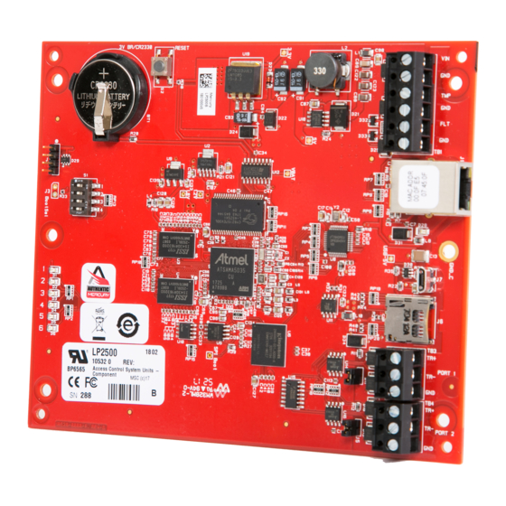
LP2500 Intelligent
Controller
Installation and Specifications
1. General
The LP2500 intelligent controller provides decision-making, event reporting, and database storage for the
Mercury hardware platform.
The LP2500 communicates with the host via on-board 10-BaseT/100Base-TX Ethernet port or the Micro USB
port (2.0) with an optional Micro USB to Ethernet adapter. Sub controllers are connected via ports 1 and 2
using 2-wire RS-485 multi-drop communication busses. The LP2500 requires 12 to 24 Vdc for power.
2. LP2500 Hardware:
S1: DIP SWITCHES
STATUS
LEDs
.50 [12.70]
.25 [6.35]
3. LP2500 Wiring and Setup:
TB1-1
Power Fault
TB1-2
Input
TB1-3
Cabinet
TB1-4
Tamper Input
TB1-5
Power Input
TB1-6
TB2
N/A
Terms A & B are from the RS-485 standard
Note 1:
Mercury Security © 2018
2355 MIRA MAR AVE. LONG BEACH, CA 90815-1755, (562)986-9105 FAX (562) 986-9205
3V BR/CR2330
S1
1
2
3
4
1
2
3
4
5
6
LP2500 Layout
CONNECTION
GND
FLT
GND
TMP
GND
VIN: 12 to 24 Vdc
Not Used
LP2500
This device complies with part 15 of the FCC Rules. Operation
is subject to the following two conditions: (1) This device may
not cause harmful interference, and (2) this device must
accept any interference received, including interference that
may cause undesired operation.
BATTERY: BR/CR2330
REPLACE ANNUALLY
S2: RESET
SWITCH
6.00 [152.40]
5.50 [139.70]
CONNECTION
TB3-1
SIO Port 1
TB3-2
(2-wire RS-485)
TB3-3
TB4-1
SIO Port 2
TB4-2
(2-wire RS-485)
TB4-3
DOC 10107-0063
REV 1.02
www.mercury-security.com
Ø.156 [3.96]
6 PLACES
VIN
TMP
GND
J1: ETHERNET
FLT
JACK
GND
TB1
EARTH GROUND
J7: MICRO USB
D28
JACK
J6: MICRO SD
CARD SLOT
J7
J6
TB3 & TB4
RS-485 PORTS
TB3
TR+
PORT 1
TR-
GND
TB4
TR+
TR-
PORT 2
GND
GND
TR- (B) See note 1
TR+ (A) See note 1
GND
TR- (B) See note 1
TR+ (A) See note 1
Page 1
Advertisement

Related Manuals for Mercury LP2500


Summary of Contents for Mercury LP2500
- Page 1 The LP2500 intelligent controller provides decision-making, event reporting, and database storage for the Mercury hardware platform. The LP2500 communicates with the host via on-board 10-BaseT/100Base-TX Ethernet port or the Micro USB port (2.0) with an optional Micro USB to Ethernet adapter. Sub controllers are connected via ports 1 and 2 using 2-wire RS-485 multi-drop communication busses.
- Page 2 USB Port (2.0) DIP Switches: The four switches on S1 DIP switch are used to configure the operating mode of the LP2500 controller. DIP switches are read on power-up except where noted. Pressing reset switch S2 causes the LP2500 to reboot.
-
Page 3: Communication Wiring
2. Apply power to the LP2500 board. LED 1 on for about 15 seconds while LP2500 boots up. 3. After the LP2500 boots up, watch for LEDs 1 & 2 and 3 & 4 to alternately flash at a 0.5 second rate. -
Page 4: Status Leds
Upon installation, the user accounts to the web configuration page should be created with secure passwords, and that all DIP switches are in the off position for the normal operating mode. The LP2500 is shipped from the factory with a default login account, which is enabled when DIP 1 is moved from OFF to ON. - Page 5 These specifications are subject to change without notice. Warranty Mercury Security warrants the product is free from defects in material and workmanship under normal use and service with proper maintenance for one year from the date of factory shipment. Mercury Security assumes no responsibility for products damaged by improper handling or installation.
Need help?
Do you have a question about the LP2500 and is the answer not in the manual?
Questions and answers